
Introduction and Rationale
Our ECE 4760 design project integrates three different kinds of sensor measurements to track a users movement speed, regularity of gait, force on impact, pronation of foot, as well as other information that may be useful to a podiatrist. We believe there is a need for a cheap metering tool that can be used to log long-term data for later interpretation by a podiatrist.
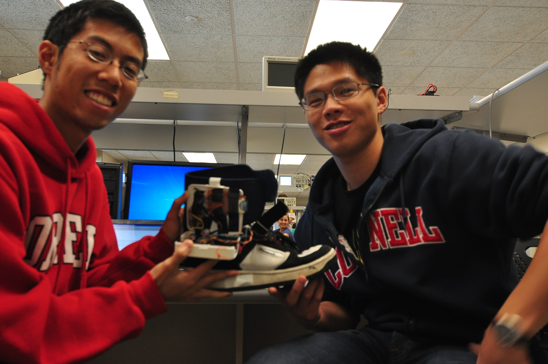
Wen Jie and Yilok with said Shoe
Rationale and Sources of Inspiration:
During normal walking motion, our feet absorb the shock of impacting the ground by rolling inwards towards the center of the body, distributing weight evenly across the entire foot. Unfortunately, only a quarter of the population are considered "neutral" footed, without any noticable problems with their gait. Half the population suffer from over-pronation, where the feet roll too far inwards causing undue stress to the arch of the foot. The remaining quarter suffer from the opposite problem, supination. Problems associated with incorrect walking form include knee/ankle injuries and foot pain. We hope our project will help podiatrist analyze the problems associated with over-pronation/supination by providing an affordable data measurement/logging device. Using an integrated SD card, each patient would be able to provide weeks worth of data to the podiatrist, capturing the many activities we encounter throughout the day. Treatment and custom othropedics can then be personalized. We imagine our project would also have sports applications, as the data can help improve the form of the user.
Inspiration for this project came from many directions. The original idea was conceived of during a lapse in productivity in a brainstorming session. One group member curiously asked why the outside edge of the other member's
shoe was much more worn out than the inside edge. Wikipedia quickly provided the answer, and soon we had a working proposal. Further motivation came from the fact that the group member suffers from knee pain, one of the highlighted
symptoms of supination. Our professor, Bruce Land, supported our idea and provided further ideas that extended off our basic premise.
Sources:
http://www.runwashington.com/archive0209/features/brieforthoticsquestion.html
High Level Design
Our project consists of three main functions
- Data Measurement
- Data Processing
- Data Storage/Output
Data Measurement
Our data measurement function primarily replicates the abilities of an inertial measurement unit in a more specified manner. We considered purchasing IMUs directly from Sparkfun, however we decided to save on costs by sampling accelerometers and gyroscopes separately and implementing signal processing in the microcontroller. Since the ATMega644 has eight channels of analog-to-digital converters, we were able to include force-sensitive-resistors (FSRs) to our project. These resistors greatly decrease in resistance when a force is applied to the surface. By placing the sensors in strategic locations, we are able to figure out relative force distributions across the foot. Initially we sampled a digital output gyroscope from Analog Device. We had great difficulties with soldering the tiny packaging to a breakout board, and once it was soldered we could not get the device to interface via SPI. Because we had room in our budget and to save on time, we ordered an analog output gyroscope from Sparkfun because we had already successfully set up multiple ADC readings with the accelerometers and FSRs.
Data Processing
Data processing conducts multiple functions to sense user steps, detect the pronation of a user, log their angular movement of the foot as it moves through the stride, as well as output curves of the user. By using the network of sensors embedded in the shoe, a basic model of how the user moves about can be generated.
Data Storage/Output
We began our design with a simple writing to EEPROM to store data values after shutdown, however we quickly realized that this would not be an acceptable solution since reading from EEPROM requires
AVR studio and more importantly, our dataset would be limited to around 2000 values. With a sampling rate of 100 ms, this turns out to be about four minutes worth of values for just one accelerometer.
After examining past projects, we decided that an SD card interface would be the best way to store large amounts of data and easily transport it from the shoe to a desktop computer. Once on the computer,
the values can be parsed by MATLAB or some other custom program and the dataset can be easily plotted to reveal patterns in the user's stride.
We also considered using an LCD screen to view the analog outputs and used one during the early testing phases of the project. However, as we began integrating the hardware into the shoe, we relied more upon
outputs to Putty via the serial port, and eliminated the LCD display entirely. If we are able to achieve wireless function, we may explore the possibility of sending data wirelessly to a receiver point, and then
displaying it via LCD, maybe like a watch.
A wireless RF transmitter and receiver pair was also attempted, but after failed attempts in getting the USART output to sync properly, the wireless portion was scrapped in the interest of time. The original design
was to attach a TLP 434 transmitter to the TX pin on the microcontroller while setting up an rf "sniffer" with the receiver feeding its output to an FTDI232R chip which interfacted to a computer via USB. Essentially,
the wireless implementation would have almost no overhead compared to the wired version except for the lack of a wire. It was found that wireless noise de-synced the USART communication between the MCU and the FTDI232R
chip, so jumbled garbage was received. A brief attempt was made at creating packet headers to ensure reliable transmission, but was halted due to time considerations.
Software Design:
Our software is broken up into three main modules much like our high level design. Final_Project.c/.h, maintains program control flow and data collection. We modularized the signal post processing in calculations.c/.h and SD card functionality in sdcard.c/.h to promote independent parallel development. We have future plans of rewriting the program to be multi-threaded so that all of our monitoring tasks can be simultaneously run and output to a functional GUI. Much of the code for accessing the SD card was adapted from prior ECE 4760 projects. It utilizes the FatFS hardware abstraction layer system, which provides a very intuitive API for handling the specifics of integrating the SD card.
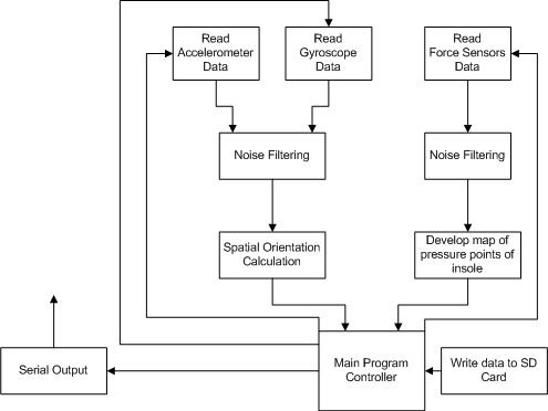
Top Level System Architecture (from Project Proposal)
Main Controller
Unlike previous projects, we did not find a need to build a state machine to manage program state. Instead, we set up Timer0 to trigger an ISR every millisecond, which is responsible for managing the timing of several crucial
components. It decrements a program counter to trigger the sensor readings every 100 ms. The FatFS specification requires that a time and date stamp be provided to it, which is implemented by a several counters variables that is incremented
within the ISR. Additionally, we decrement one additional timer at a rate of 100 Hz to handle the delay timing for the SD card.
Our sensor array utilizes three FSRs, two accelerometers, and one dual-axis gyroscope. All our sensors utilize analog outputs, therefore we utilize seven out of eight ADCs on the ATMega644. To switch between the different channels of the ADC,
we assign the 3-bit binary value corresponding to that channel to MUX2:0 bits in the ADMUX. It is important to maintain a logic high in the REFS0 bit of ADMUX throughout the changing of ADMUX. One of our initial problems was ADC output values that
were nonsensical because the ADC was referencing the value of the input to some arbitrary AREF, instead of Vcc.
Unlike previous labs, we wanted the full 10-bit resolution of the ATMega644's ADC. A wrapper function, read_ADC() writes a logic high to the ADSC bit in the ADCSRA to start the conversion. The conversion takes an unspecified amount of time,
therefore the only way to ensure proper timing is to trap the execution of the program in a while loop as long as the ADSC bit remains high. Once ADSC goes low, the conversion is finished and both ADCL and ADCH can be read.
The datasheet specifies that ADCL must be read before ADCH, otherwise the results of another conversion may erase the values in the register. For simplicity's sake, we chose to right align our data outputs, meaning the 8 least significant bits
of the data will be in ADCL, and the 2 remaining MSB will be in ADCH. Combining the inputs simply requires a logical OR between ADCL and ADCH left shifted by 8 bits.
Rather than write each reading to the SD card at the end of a full set of ADC conversions, we chose to store it in a buffer. Once the buffer is full the program calls the helper functions in the SD card module to write all the values in the buffer to the SD card.
Writing to the SD card requires a significant amount of time relative to reading from the ADC values. We chose to have a longer delay, on the order of several seconds, every 100 readings of the ADC rather than having a delay at the end of each ADC read.
Using this method, our program requires more data memory, increasing usage by about 30%. If we were close to our budget, we could have opted to use ATMega16 microcontrollers instead, and run the ADC conversions at a slower rate.
Data Monitoring
A debug mode of our device allows the microcontroller to read ADC values from all its devices and print them out in a pretty format for analysis. In a medical application, the shoe can then constantly stream data through USART as strings for post processing on another machine.
Step Detection Processing
While we were collection data, it was discovered that we could implement step detection in multiple ways. Both the FSRs and the accelerometers output consistent enough data that both the falling and rising acceleration or the impact of the foot
pressing into the ground and releasing for the next step could be used to detect a step. In our design, we elected to use the accelerometers to implement a three-state state machine to detect and debounce a step. When the ADC value of an
accelerometer surpasses a set threshold value, the state machine goes to a "STEPUP" state where it has detected a rising foot and will await for the falling sequence. If the falling sequence does
not occur within 0.8 seconds, the state will timeout and return to a waiting, "TRACKING," state. If a falling acceleration occurs before the timeout and surpasses a falling threshold, then a step is said to have been
taken. In field tests, we found that by adjusting the threshold values, we were able to step detect quite well.
Currently, step detection keeps track of the number of steps taken. We could have also multiplied the steps taken by an average stride length to display approximate distance walked.
Pronation Detection
Pronation detection is also done via a state machine, but in this case, we elected to use the force sensors. Pronation detection triggers when the heel FSR force
surpasses a set threshhold to signal the heel taking most of the subject's weight as they roll toward the front of their foot. The state machine then waits a short period for the front sensors to
surpass their respective thresholds during a certain timeout window. If a forefoot force is detected, the exact force sensor that fired is located
and depending on its physical location, pronation or supination can be determined.
We were originally planning to use our gyroscope to detect the exact degree of rolling that a foot undergoes when makign a step, but conversions and integration
of the ADC values from the gyroscope resulted in degree values that drifted linearly. This drift made most of our programming useless, so in the end, the more
simplistic FSRs were used.
Writing to SD card
As previously mentioned, our project makes extensive use of the work done by previous ECE 4760 students as well as the FatFS system. In particular, we referenced the following ECE 4760 projects:
Adaptive Alarm Clock
GPS Data Logger
One of the reasons we chose to use SD cards for our data storage was because the interface is accessible via SPI, which is easily implemented with the ATMega644. Essentially, FatFS modularizes all the commands and timing so that the user only needs to
worry about setting up the microcontroller with the right SPI configuration. This is done in mmc.c. As per the documentation on the FatFS website, the microcontroller should be set as the master, and the phase and polarity
both set to logic low. Within the initialization function of mmc.c, pins B.4(Chip Select), B,5(MOSI), and B.7(SCLK) are set to logic high to designate those pins as output. Fortunately, the two previous groups modified their mmc.c to work with the
ATMega664, and we had no difficulties from a software perspective. We did have issues when we first tried to implement the SD card because of hardware problems, which will be discussed in the next section.
To set the SD card to communicate via SPI, the following intialization process must be completed:
- Set the SPI clock to 125 kHz
- Wait 80 clock cycles by transmitting a generic SPI command ten times
- Send CMD0 to enter SPI mode in idle mode
- Determine what type of card (SDHC/SD/MMC) by sending the following commmands in order, until one returns a logic high: CMD8, ACMD41, CMD1
- Restore fast clock rate
Writing data to the SD card accessed by calling helper functions provided by FatFS. The file is first opened by calling f_open() passing in the pointer to the FResult object as well as the access type. Writes are done by formatting a string using snprintf and passing the FResult pointer,
the formatted string, and the length of the data to be written. FatFS hides the implementation details such as the specific command to send as well as the number of commands (since only eight bits of data can be sent at once through SPI).
FatFS is distributed free of charge without any licenses restricting usage.
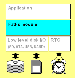
FatFS diagram
Hardware Design
For our project, we used the following hardware functional blocks:
- ATMega644 Target Board
- Freescale MMA1260D Accelerometer
- Sensitronic/Interlink Force Sensitive Resistors
- LPR503AL Dual-Axis gyroscope
- SD Card Module
- 5V to 3.3V Voltage Converter
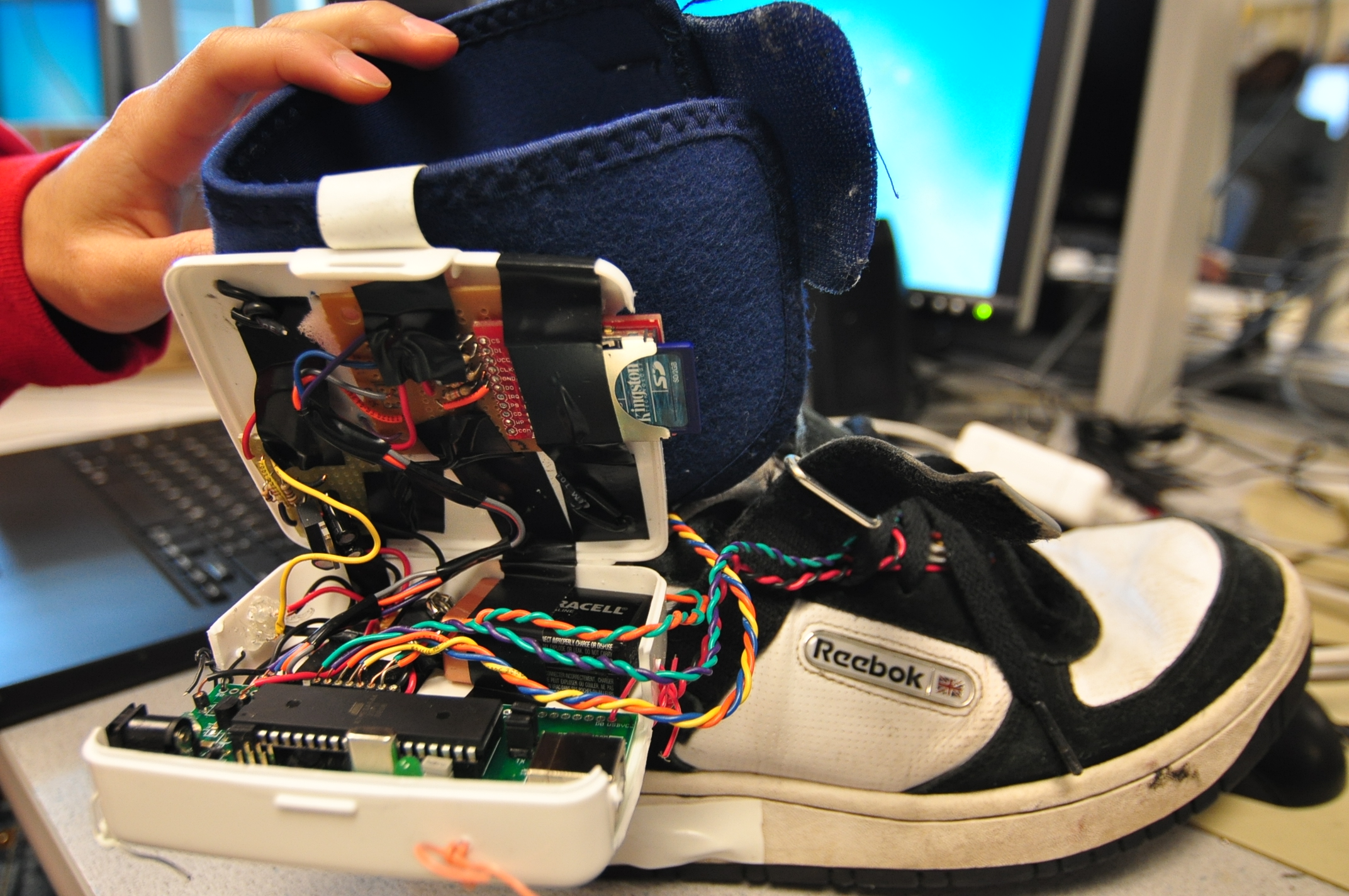
Hardware Integrated into Shoe
ATMega644 Target Board:
The ATMega644 target board provides the user with a small, portable platform to interface with the ATMega644 chip. All necessary protection resistors and bypass capacitors are provided in surface-mount format and mounted on a custom designed PCB. The PCB routes the port pins of the ATMega644 to
pins on the edge of the board, which makes interfacing with other hardware elements much easier. We used a 16 Mhz oscillator with our ATMega644.
The target board was designed by our professor Bruce Land. One major change from previous versions of the target board is the inclusion of a USB port for debugging purposes. We prefer using the FT232R USB-to-serial UART iterface because we do not feel confident
in the quality of the serial-to-USB converters. We used a LED to tell us when the board was being powered and active. Because we planned to run the target board on our shoe, we soldered leads to a 9V battery clip.
Total parts list for the target board:
- Mega644-20PU Atmel microcontroller
- MAX233CPP dual RS232 interface or FT232RL
- USB female connector
- LM340LAZ-5.0 regulator
- CTX077 16 MHz crystal
- Switch SPDT surface mount AYZ0102AGRL 401-1001-1-ND
- 2.1 mm power plug CP-002A-ND
- 9 volt battery clip 84-6k-ND
- All resistors and capacitors are 1206 surface-mount packages
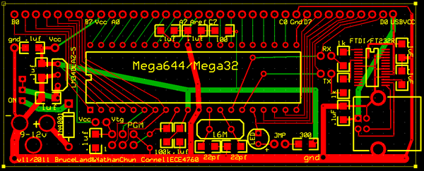
Target board PCB
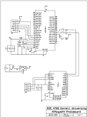
Target board schematic
More information on the target boards can be found here: Target Boards
All images are property of Bruce Land.
Freescale MMA1260D Accelerometer
We used the Freescale MMA1260D accelerometers donated to ECE 4760 lab by Freescale Electronics. There were many variants with different maximum acceleration ratings, but we chose the 1260D with a maximum acceleration of +/- 1.5g because we preferred resolution over bandwidth. During normal standing position, the accelerometer will read out approximately 1g. We do not think that during normal walking motion, the acceleration would exceed the bounds of the accelerometer. We developed a quick prototype by taping an accelerometer to our shoe to verify our assumption. Another desireable feature of the accelerometers was the analog output. We were much more comfortable using the ADC converter than the SPI interface. A decoupling capacitor is used between Vcc and ground. The analog output signal is filtered through a simple RC low-pass filter to remove the clock noise.
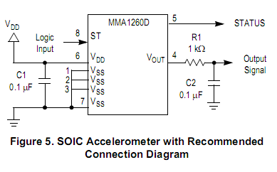
Accelerometer schematic
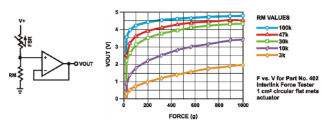
Sensitronic/Interlink Force Sensitive Resistors
We used three FSRs underneath the insole of our shoe to supplement our pronation/supination detection by analyzing the force on both the inside and outside edge of the shoe. The FSRs vary in resistance greatly as force is applied to them. Although the decrease is not linear, we can get a rough idea of relative force. We used the FSR as the resistor tied to Vcc in a voltage divider. Through trial and error, we determined that a 1K resistor tied to ground provided the best resolution throughout the range of forces applied during normal human gait for the sensors at the ball and outer edge. Since less force is on the heel, we used a 330 ohm resistor for that sensor only. As more force is placed on the FSRs, the resistance drops and a greater voltage is dropped across the series resistor, leading to a higher ADC value.
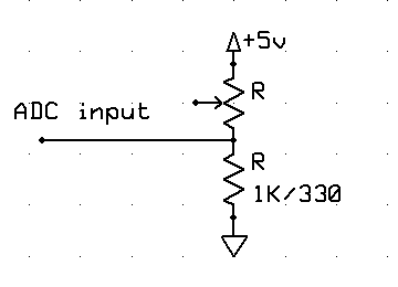
FSR schematic
FSR datasheet
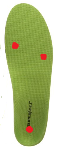
FSR location on insole
LPR503AL Dual-Axis gyroscope
To measure the angular movement rate of the shoe, we decided to use a gyroscope to simplify our data processing. Initially we had received samples of the ADXRS450 digital accelerometer from Analog Devices. The packaging type of the samples were designed to be surface mounted and were extremely difficult to solder. We successfully soldered the small accelerometer to a solderboard, but we were unable to interface it via SPI. We believe the accelerometer may have been damaged by the heat during soldering. Although we probably could have used the two accelerometers to accomplish the same function, the analog output of the gyroscope was much easier to use. The breakout board already contained all the necessary filtering capacitors and header pins. We provided 3.3V and connected the 1X outputs to our ADC and instantly had results.
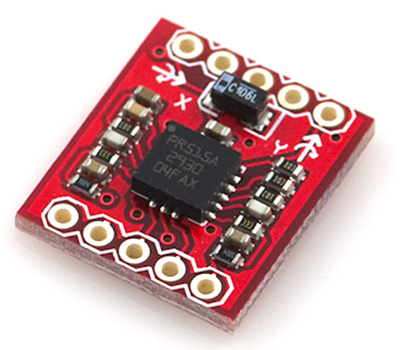
LPR503AL
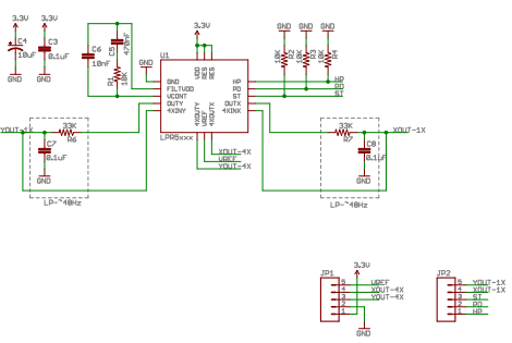
Schematic of breakout board
We purchased our gyroscope from Sparkfun: LPR503AL Dual-Axis gyroscope
SD Card Module
Initially we tried to save on costs by directly soldering header pins onto a SD card, however that method formed an unreliable connection on the solderboards. We decided that the $10 cost of a SD card breakout board from Sparkfun was worth it for the peace of mind. Once the breakout board arrived, we soldered it onto a larger solderboard. Because the ATMega644 pins output 5V for logic high, we needed to level-shift the microcontroller outputs to 3.3V. We adapted the same circuitry that the "GPS Logger" project used. A diode is placed between the 3.3V Vcc and the pin on the SD card. A 1K resistor lies between the pin on the SD card and the microcontroller pin. When the pin is driven logic high, the diode is conducting and since it has a low forward voltage drop, the SD card pin is held at about 3.3V. When logic low is driven, the diode no longer conducts and the SD card also sees a logic 0. A 57K resistor is used on the MISO pin as a pull-up resistor.
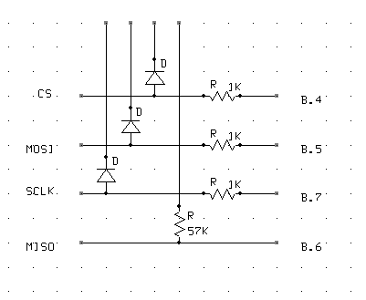
SD Card level shifter
5V to 3.3V Voltage Converter
Our gyroscope and the SD card interface require a 3.3V Vcc instead of the 5V provided by the microcontroller. Initially, we used a simple voltage regulator constructed from an 2N3904 NPN transistor, 5K resistor, and a potentiometer. While we were experiementing with the SD card, we noticed that the output of this regulator was strongly affected by the load resistance. We would adjust the potentiometer such that it would output 3.3V. When we attached the SD card, no matter how we adjusted the potentiometer, the circuit would output roughly 4V. This was out of the SD card specification, and caused major issues when the microcontroller tried to send SPI commands.
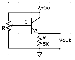
Simple voltage regulator
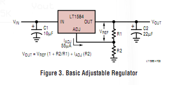
Fortunately, we were able to sample an adjustable voltage regulator from Linear Technologies, the LT1584. The output voltage is adjusted by establishing a Vref using a simple resistor voltage divider. According to the datasheet, the output voltage follows the formula: Vout = Vref(1 + R2/R1) + Iadj* R2. The circuit schematic is shown below. Using resistor values, R1 = 330 ohms, R2 = 500 ohms, we were able to achieve a steady 3.2V output, which is within specification for both the gyroscope and the SD card.
SD Card Module with Voltage Regulator
Simple voltage regulator
More information on the LT1584 can be found here: LT1584
The datasheet is provided below in our datasheets section.
Overall Circuit Diagram
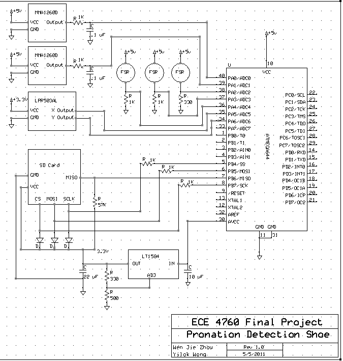
Overall Schematic
Standards:
SD Card
The SD card standard is defined by a consortium of memory manufacturers named the SD group. Their latest release, revision 2.0, can be found here. Our design does not implement the full SD card standard because we wanted to avoid additional complexity with implementing the SD bus. Instead, we implement the part of the SD standard that utilizes SPI communication.
Results
Data Gathering and Execution
Hardware wise, the circuits that we built performed exactly as designed. Each of our sensor elements output consistent data and never failed. We were able to stream data from all of the sensors out serially while also storing the data and analyzing it for steps and pronation. Future code revsions will implement a realtime OS such as Tiny Real-Time so that each function to gather data is run as a seperate thread concurrently.
Results
Results Analysis
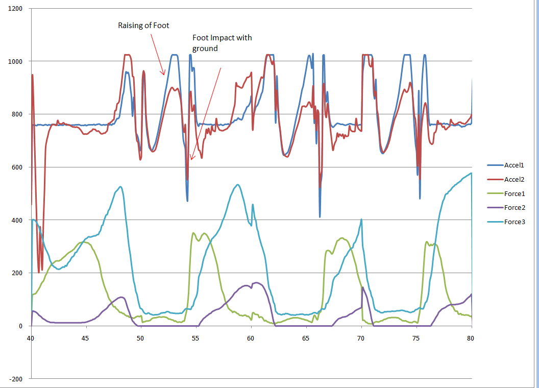
In the above graph, accelerometer 1 is the left side, accelerometer 2 is the right side, force 1 is the heel, force 2 is the ball, force 3 is the outside edge of the foot. We primarily use the accelerometer to detect the raising of the leg at the beginning of a step and the moment of impact. Both these events have sharp peaks that we look for in software. One step is composed of two or three peaks, with the second or third peak attributed to oscillations upon impact. We found that the resolution and accuracy of the accelerometers were not high enough for supination/pronation detection. Instead, we rely upon our force sensors. The current wearer is a known supinator due to the outside edge of his sneakers being worn away. As the force curves show, during normal gait the heel strikes first, as shown by the peak of the green line before the purple or blue. A supinator then rolls along his outside edge of the foot before putting a minor amount of pressure on the ball. Our graphs clearly indicate this via the huge peak on the blue curve just before a slight peak in the green curve.
Project Scope
The scope of our project had to be reduced after our initial troubles with the Analog Devices gyroscope and a wireless implementation. We feel that although the device lacks a nice wireless interface with a computer, the shoe can still be invaluable in medical applications as well as hobbyists applications. The raw data output enables any adventerous modder to write their own program to parse the serial output which can lead to the use of sensor data in conjunction to measure jumping airtime, user velocities through kinematics, stomping forces, and perhaps even a game that uses the shoe as a controller.
Safety:
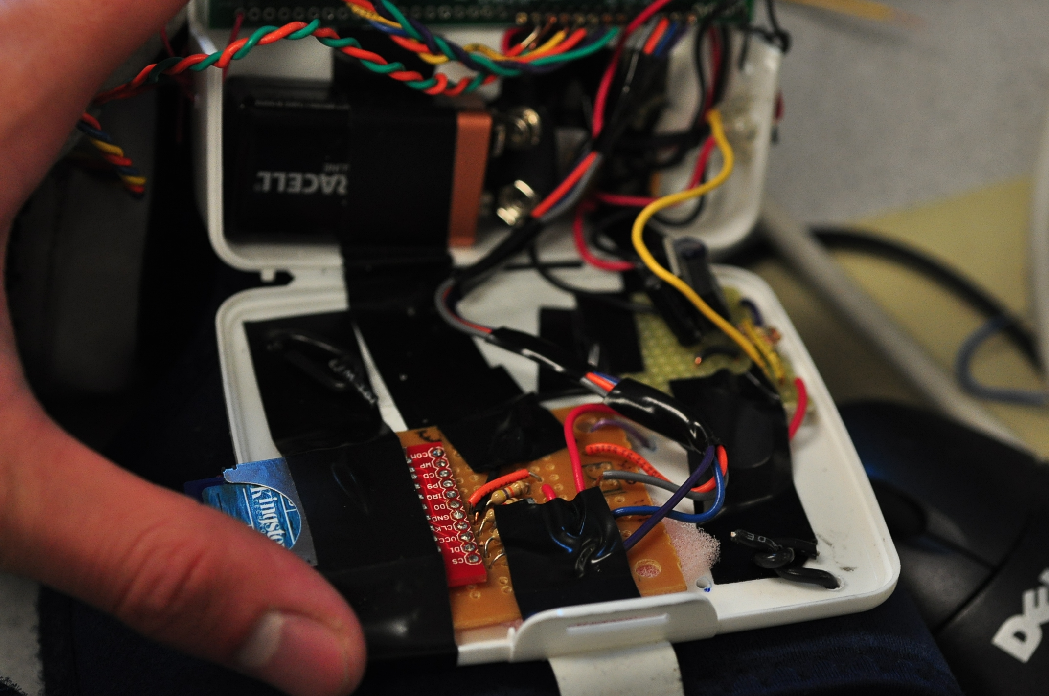
The shoe device poses no risks nor dangers to the general public. All the electronics of the device are contained in antistatic bags or a safety box
that attaches to the users ankle. This box contains the microcontroller, multiple bus boards, voltage regulators, a battery, and the SD Card. It allows easy access to critical parts of the
device while keeping everything intact and safe during use.
In order to embed the sensors in the best data gathering location, we hollowed out significant sections of the midsole. Although this allowed us to gather accurate data, it should be noted that the midsole
provides most of the support in the shoe. Wearing a shoe without a solid amount of support is dangerous. In a commercial setting, the sensors would be embedded into the midsole during the production process
without affect support.
Interference:
The shoe has very few, if any interference issues. The lack of wireless implementation and a secure enclosure prevent most possibilities of radio noise.
Usability:
As a medical data logging device, the shoe is quite useable and does a fine job at the price and size of its components. In production all of the electronics would be shrunk and the device would be a very good runner-hobbiest device to not only keep track of distance run, steps, and calories burned, but also amount of force that each part of your foot is dealing with as one walks.
Conclusions
We feel that our prototype implementation of a proof of concept performed to reasonable expectations. Although many of our fancier features had to be dropped along the way, the core functionality of our device is usable and useful. We did obtain our goal of designing and building a cheap metering tool for podiatrist or hobbyist use. Refrencing our intial roadmap to our prototype, we achieved every single "Core Functionality" goal as well as about a third of the "Phase 2 Functionalities."
Future iterations of the device will take the current large embedded devices and attempt to print them as small surface mount pieces on a much thinner flexible conductive surface. Much of the current project bulk comes from the unavailability of circuit board printing tools. The software control programs would also be rewritten to allow multithread functionality between data gathering functions and data printouts.
We were unable to implement a few features that we had planned to include in our initial prototype. The features were RF communication to PC, pronation angle, and using the Analog Devices ADXRS450 digital gyroscope. With RF communication, a wireless receiveing module was built and the transmission module was also built, however, we were not able to set up a noiseless communication channel. Attempts were made to reliably send packets, but time restrictions forced us to cut this feature out. Time restrictions were also why exact pronation angle could not be calculated. The calculated integrated angle had too much linear drift to be useful. Finally, a full week of our initial lab time was spent construction and debugging an sampled Analog Devices ADXRS450 digital gyroscope. It's fine pitch surface mount soldering proved to be too much of a challenge for us. When everything was soldered on, it sent us terrible data through the MOSI and MISO lines. We suspect this was due to heat damange to the gyroscope from oversoldering. There were a couple of software issues. Because the programming is linear, functions to measure pronation and functions to measure walking steps cannot be simultaneously run. Future editions of the running firmware will implement a real time operating system to take advantage of threads and multithreaded running of code.
Ethical Considerations:
Our project follows the IEEE Code of Ethics and during the development of the shoe device, no ethical concerns occured or were brought up.
This device poses no threat to the public and instead is designed to assist the public in enjoying their lives. All the electrical devices on
the shoe are properly electrically isolated from a wearer and the electronics box also reduces the possibility of an electrical hazhard occuring if
and individual wearing our advice were to end up in a compromising situation.
If used in an actual medical setting, the data obtained with our device could have real implication for patients and may influence doctor opinions and treatment.
To uphold the IEEE Code of Ethics, we need to pay special attention to ensure that the data is accurate and reliable. In addition, our design needs to be safe to use
for people with health issues.
Intellectual Property Considerations:
The idea of a shoe device to monitor one's movements was an idea what we both brainstormed. Upon doing some online research, we found that a similar project was currently under research by Erez Lieberman, a graduate student in the Harvard-MIT Division of Health Sciences and Technology. His product, the iShoe, was developed to enable "early diagnosis and rehabilitation of deteriorating balance for aging adults." To ensure that our project didn't infringe upon the iShoe, we moved our design away from foot balance to pedometry as well as general hobbyist monitoring systems.
Societal Impact:
This inexpensive foot monitoring device can be used in various ways by the public. Podiatrists can use this device for simple examinations to determine if a patient is standing or walking in an unusual way. Casual runners can find how they are pronated and by how much to determine an ideal running shoe for them. If they'd rather not decide for themselves, they can also bring in their SD card of running data in to a professional to be analyzed. More professional runners and/or hobbyists can use the shoe to monitor their running form and patterns. They can monitor their force curves to see if their legs are smoothly transfering weight from foot to foot.
Acknowledgements:
We would like to thank Bruce Land for motivating us throughout the semester. This was by far one of our more enjoyable labs of our undergraduate careers!
Division of Work:
| Wen Jie | Yilok |
| SD Card Implementation | Wireless TX/RX exploration |
| Hardware Integration and Packaging | Step Detection/Signal Processing |
| Hardware soldering/assembly | Hardware soldering/assembly |
| Main control loop | Main control loop |
| Final Report | Final Report |
| Website Design | Target board assembly |
Appendix
Parts List
| Part | Manufacturer/ Supplier | DigiKey Part Number | Unit Cost | Quantity | Total |
|---|---|---|---|---|---|
| Housing and Ankle brace | - | Previously owned | $0.00 | 1 | $0.00 |
| Shoe | - | Previously owned | $0.00 | 1 | $0.00 |
| SD card breakout board | Sparkfun | - | $10.00 | 1 | $10.00 |
| Adjustable Regulator | Sampled | LT1584 | $0.00 | 1 | $0.00 |
| Accelerometers | Freescale | MMA1260D | $0.00 | 3 | $0.00 |
| Gyroscope | Sparkfun | LPR530AL | $30.00 | 1 | $30.00 |
| Interlink FSRs | Sampled | - | $0.00 | 3 | $0.00 |
| Diodes | ECE 4760 Lab | 1N4001 | $0.00 | 3 | $0.00 |
| Small Solder board | ECE 4760 Lab | - | $2.00 | 3 | $6.00 |
| 9V Battery | ECE 4760 Lab | - | $2.00 | 1 | $2.00 |
| Custom PC Board | ECE 4760 Lab | - | $4.00 | 1 | $4.00 |
| ATMega644 | ECE 4760 Lab | - | $8.00 | 1 | $8.00 |
| DIP sockets | ECE 4760 Lab | - | $0.50 | 1 | $0.50 |
| Header Pins | ECE 4760 Lab | - | $0.05 | 16 | $.80 |
| Misc: Caps/ Resistors/ Regulators | ECE 4760 Lab | - | $0.00 | 1 | $0.00 |
| Total | $68.50 |
Schematics:
Level ShifterOverall Schematic
Code Listings:
Our code is available as a zip file here: Zip file of Code
References
Previous Projects
Adaptive Alarm Clock
GPS Data Logger
External Libraries
FatFS website
SD card specification
ECE 4760 Website
Datasheets
Interlink FSR402 Datasheet
MMA1260D Accelerometer datasheet
LPR530AL Dual-axis Gyroscope datasheet
LT1584 datasheet
ATMega644 datasheet