High Level Design
Quadcopter
A quadcopter is a multicopter lifted and propelled by four rotors. The motors are mounted in the same plane, on the helicopter, forming a square. This allows this quadcopter to lift vertically without rotating on itself. There are several advantages to quadcopters over comparably-scaled helicopters. The fact that four motors are involved reduces the minimum size of the propellers on each motor. This means that in case the quadcopter hits anything the damage is significant less than if a similar sized helicopter crashed. The following figure shows how the motors are mounted. The rotation direction is critical to the correct functioning of a quadcopter.
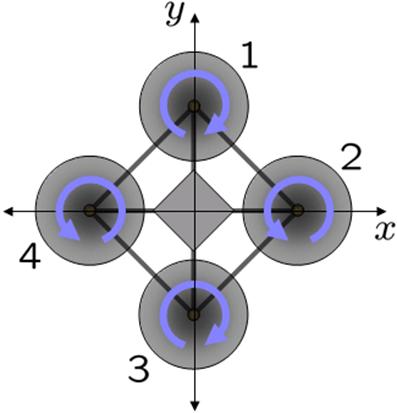
source: wikipedia
All motors have to rotate at the same speed for a vertical lift; however, motor 1 and 3 have to rotate opposite to motors 2 and 4. This is necessary to compensate the angular acceleration generated by each motor. This way the total angular acceleration should be zero, maintaining the quadcopter stable.
According to Wikipedia, flight dynamics is the science of air vehicle orientation and control in three dimensions. Roll, pitch and yaw as shown in the picture below are the three critical flight dynamics parameters, which are the angles of rotation in three dimensions about the flying object's center of mass. In our project, we use our IMU chip to measure these values and also employ the PID (proportionalintegralderivative controller) system from lab 4 to fine-tune them. Roll, pitch, yaw and throttle (up and down) movements are controlled by an Xbox joystick.
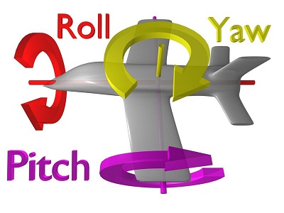
source: wikipedia
Accelerometer and gyroscope
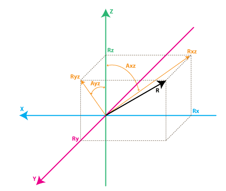
An accelerometer is an electromechanical device that measures acceleration forces. There is an excellent tutorial on the web at http://www.instructables.com/id/Accelerometer-Gyro-Tutorial/step3/Combining-the-Accelerometer-and-Gyro/ Let us briefly explain how accelerometers and gyroscopes work (a summary from the website). Let the vector R in the diagram below be the force vector that the accelerometer is measuring. Rx, Ry, and Rz are projections of the R vector on the X, Y, and Z axes.
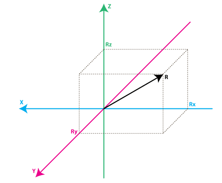
source: http://www.instructables.com
Each accelerometer has a zero-g voltage level (it can be found in a datasheet), which corresponds to 0g. Let VzeroG be the 0g voltage level and then the voltage shift from zero-g voltage, DeltaVoltsRx, is Rx VzeroG. To convert the value to g (9.8 m/s^2), we need to apply the accelerometers sensitivity in mV/g (its found in a datasheet). Finally,
Rxg = (Rx-VzeroG) / Sensitivity
Ryg = (Ry-VzeroG) / Sensitivity
Rzg = (Rz-VzeroG) / Sensitivity
Now if we want to calculate inclination of the quadcopter relative to the ground, we can calculate the angle between the vector R and Z axis. Lets define the angles between X, Y, Z axes and the force vector R as Axr, Ayr, and Azr as in the diagram below:
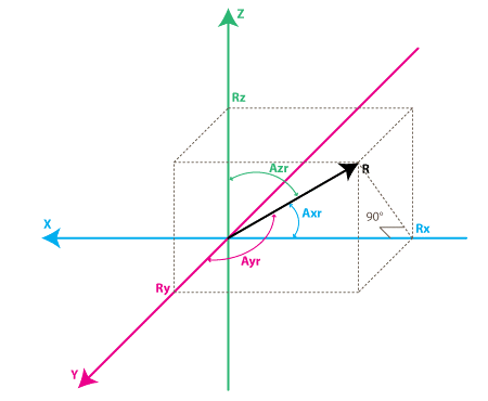
source: http://www.instructables.com
From the diagram above, we derive that
cosX = cos(Axr) = Rx / R
cosY = cos(Ayr) = Ry / R
cosZ = cos(Azr) = Rz / R
Axr = arccos(Rx/R)
Ayr = arccos(Ry/R)
Azr = arccos(Rz/R)
Each gyroscope channel measures the rotation around one of X, Y and Z axes. Lets define Rxz as the projection of the inertial force vector R on the XZ plane and Axz as the angle between the Z axis and Rxz. Gyroscope measures the rate of changes of the angles like Axz in deg/s. Similar to accelerometer, we apply the gyroscopes zero-rate voltage and sensitivity (mV/(deg/s)) to get
RateAxz = (GyroXZ VzeroRate) / Sensitivity
source: http://www.instructables.com
Unfortunately, accelerometer data cannot be trusted 100% due to accelerometers sensitivity to vibration and mechanical noise. Gyroscope also has problems such as drifting even when rotation stops So, we combine accelerometer data and gyroscope data for better accuracy.
Lets first define a vector Rest = [RxEst, RyEst, RzEst] as the final output we want. Rest is the corrected value based on the current gyroscope data and past estimated data. Also define Racc = [RxAcc, RyAcc, RzAcc] as a vector currently measured by the accelerometer. Then, Rest(0) = Racc(0). Suppose we make regular measurements at equal time intervals of T seconds and Rest(n-1) is our previous estimate when were at step n. The value obtained from the gyroscope and a previous estimate is defined as Rgyro = [RxGyro, RyGyro, RzGyro]. From the diagram above, we can get
tan(Axz) = Rx / Rz => Axz = atan2(Rx, Rz)
Axz(n-1) = atan2( RxEst(n-1) , RzEst(n-1) )
Axz(n) = Axz(n-1) + RateAxz(n) * T
RateAxzAvg = ( RateAxz(n) + RateAxz(n-1) ) / 2
|Rgyro| = SQRT(RxGyro^2 + RyGyro^2 + RzGyro^2)
RxGyro = sin(Axz(n)) / SQRT (1 + cos(Axz(n))^2 * tan(Ayz(n))^2 )
RyGyro = sin(Ayz(n)) / SQRT (1 + cos(Ayz(n))^2 * tan(Axz(n))^2 )
RzGyro = Sign(RzGyro)*SQRT(1 - RxGyro^2 - RyGyro^2)
Finally we use a weighted average to get Rest(n):
Rest(n) = (Racc * w1 + Rgyro * w2 ) / (w1 + w2)
Rest(n) = (Racc + Rgyro * wGyro ) / (1 + wGyro) where w2/w1 = wGyro.
As the last step we normalize the last equation to get RxEst(n) = RxEst(n)/R where R = SQRT(RxEst(n) ^2 + RyEst(n)^2 + RzEst(n)^2 ).
I2C (two wire interface)
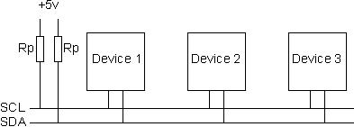
Inter-Intergrated Circuit (trademark) is a multi-master serial single-ended computer bus invented by Philips. It has maximum speed of 400kHz transfer rate. I2C consists of just two wires, SCL (clock) and SDA (data). SCL synchronizes all data transfers and only a master device can drive this line. Both SDA and SCL lines are open drain, which means that devices can only drive their outputs low but not high. Thus, as its seen in the diagram below, pull-up resistors are needed.
source: http://www.robot-electronics.co.uk/acatalog/I2C_Tutorial.html
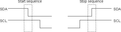
There are master and slave devices on the I2C bus (usually one master and a few slaves). A slave cannot initiate a transfer over the I2C bus, but both devices can transfer data over the I2C bus. When a master wants to talk to a slave, it issues a start sequence on the bus as in the diagram below. SDA is allowed to change only when the SCL line is high. SDA needs to be stable without a change when data is being transferred. The start and stop sequences mark the beginning and the end of the data transmission.
source: http://www.robot-electronics.co.uk/acatalog/I2C_Tutorial.html
The sequence of transmitted data consists of 7 bits for an address, 1 bit for a read/write command and 1 bit for ACK (acknowledgement), 9 bits in total. There are a few I2C libraries available on the web, and we are using twi.c and twi.h.
Back to top