Introduction
Our project is a simple game where two players control tanks in a stage with the ultimate goal of destroying each other. User input is achieved through the use of keypads, which are used to both control the tanks and fire missiles at one another.
The reason that this project was chosen was because it effectively combined most of the things we learned in this class. In addition, we all enjoy video games, and were curious if it was possible to construct an entire video game system using a microcontrollers, instead of simply the software side.
We picked this game because we wanted the demo to have more user interactions. This game allows two players to fight against each other rather than only one player playing. The game is inspired by the Nintendo "Battle City" game. We programmed this game for educational purpose only, so it is considered a fair use.
.jpg)
High Level Design
The game we have implemented is a simple adversarial game where two players control tanks in a stage and attempt to shoot each other. Terrain is in the form of walls, which are destroyed by missiles fired by tanks. User input is implemented through the use of two keypads, which are read through polling and the use of a debounce state machine, adapted from code provided in earlier labs.
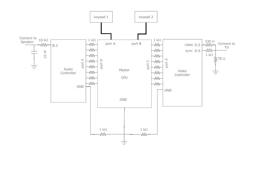
Because the Mega644 has very limited memory and frequency. We decided to move the video control and audio control out of the main processor. As we have studied, the audio controller may take more than 75% of the CPU (at 16MHz) time and 50% of the memory, and the video controller will take over 75% of CPU time and 90% of the memory. Therefore, the audio and video controller are built separately.
By having more CPUs, we have more communication overhead. The main CPU communicates with the audio controller and video controller using an 8-bit bus for each, and the ground of these three units are shared. Note that between the connection of each port, there is a 1K ohm resistor between each connection pin. This is to protect spikes from a unit when another unit turns on.
The video controller runs at 16 MHz and refresh the TV screen at 60 Hz. The resolution is 192x150. It generates a video signal and sync signal and outputs to the black-and-white TV. It’s able to update the game sprites based on the commands from the main CPU. The TV output is based on the NTSC standard.
The audio controller controls the game song and sound effect. It implements FM (frequency modulation) for the songs and DPCM (differential, pulse-code modulation) for the sound effect and the sampling frequency is 8kHz. It’s able to play different music and sound based on the commands from the main CPU. It runs at 20MHz because we think this will give the CPU more speed to handle more audio synthesis.
Some of the video code is adapted from a previous group's final project, while sound code is adapted from code used in lab3 for additive synthesis, along with matlab code taken from the course website to convert sound effects into something our sound processor can use. The game music is coded from some existing pieces of music. Since this project is only for educational purposes and we only took a small portion of the music, it is considered a fair use.
The connection of the keypad is demonstrated in lab2: http://people.ece.cornell.edu/land/courses/ece4760/labs/s2012/lab2.html
Program Design
Game Design
On a high level, the code is composed of 3 separate tasks, along with a very simple interrupt vector. Each of the 3 tasks controls a specific fucntion of the game, and the interrupt vector is simply used as a very simple scheduler in order to run each task at a certain frequency. Task1 is responsible for tracking all missiles that are in flight, along with queueing graphical and sound updates related to missile updates. Task2 handles user i/o, and consists of two debounce state machines for each player. Task3 dequeues elements of the graphical and sound buffers at a speed that our sound and graphics microprocessors can handle, and as such is also responsible for controlling communication between our 3 microprocessors.
Because of the persistent nature of player controlled tanks and missiles, both missiles and tanks were defined as structs in order to reliably keep track of their state. All missiles in flight are stored in an array that is iterated through by task1 in order to control movement and collisions with other objects. In addition, the current state of the playing field is maintained in an array, with the value of each element corresponding to the object at that position.
Interrupt Vector:
Timer 0 is set to trigger an interrupt every millisecond. When triggered, the interrupt vector simply decrements 3 counter variables, which are used to keep track of when each of the three tasks are run. This behavior is derived from the interrupt behavior of previous labs in the ECE4760 class.
Important data structures:
missile_t is a data structure used to keep track of position and direction of missiles.
p1_missiles, p2_missiles are arrays of missile_t types that are used to organize all existing missiles, along with simplifying iteration through all missiles for graphical and game updates.
tank_t is a data structure used to keep track of position and direction of each tank, with 2 initializations of player_1 and player_2.
char map[16][16] is an array that maintains the state of the entire game stage, including positions of missiles, walls, and players.
framebuffer, soundbuffer are arrays used as rotating buffers in order to keep track of and maintain commands that will be sent to the sound or graphics processors.
Functions:
initialize_system():
Initialize_system initializes all necessary state variables (data structures, queue pointers, etc.) alon with setting all ports to the correct output direction. In addition, it also sets timer 0 to trigger an interrupt every 1 ms for the purpose of scheduling tasks.
initialize_stage():
Initialize_stage initializes the map used to keep track of game state, along with initializing the data structures that keep track of all missiles in flight.
task1():
Task 1 is run 16 times a second, and is responsible for controlling all missiles currently in flight. It iterates through the missile arrays, finding all valid missiles, and then advances them one step, triggering different actions based on the contents of the contents of their new position. If there is a wall, then the missile and wall are both destroyed. If there is another missile, both missiles are destroyed. In the case of an empty space, the missile is simply moved to the new space, and if the space is the enemy player, then the player who fired the missile wins the game. This process is repeated for the missiles of both players, with changes to state as appropriate.
task2():
Task 2 is responsible for debouncing the user inputs through keypads, and is run 40 times a second. The debounce logic is virtually identical to the example code given by Bruce Land for lab1 of this class. If there is a successful button press, then the buttonpressed() function is called, which is responsible for interpreting the user input.
task3():
Task3 is responsible for dequeing graphical and sound updates off of their respective buffers, and runs 250 times a second. It essentially drives the bus used to communicate with the sound and graphics processing microprocessors, along with incrementing head pointer of the rotating buffer.
Main:
The Main function simply keeps counters for each task and calls the respective task function when appropriate.
Video Controller
The video controller is adapted from the video generation code from ECE4760 website: http://people.ece.cornell.edu/land/courses/ece4760/video/index.html
We modified the original code so as the game CPU is able to control the video more easily.
The video controller runs at 16 MHz and refresh the TV screen at 60 Hz. It generates a video signal and sync signal and outputs to the black-and-white TV.
The horizontal resolution of the video is 192 pixels, and the vertical resolution is 150 pixels. But we only use 192x130 of the screen. The game map, which is 128x128, located on the left size of the screen and an information bar is on the right side.
The main game map is further divided into a 16x16 grid, and each grid takes 8x8 pixels. The objects of the game, such as tanks, walls and bullets are located in each grid. The graphics of these objects, also known as sprites, are stored as 8x8 matrices in the memory, (as an array called objectbitmap). We define a function: void draw_object(char x, char y, char c), which will draw sprite c on the coordinate x, y of the grid from the pre-stored 8x8 matrix. Note that, the grids are represented by a 16x16 metrix, so each grid can have an 8-bit x(row) and y(coordinate) coordinate (x,y).
Sprites
Tanks: There are two tanks in the game, and their coordinates as in the grid are stored as variables. Tank 1 is the white one, and tank 2 is the black one. Note that each tank has 4 sprites, representing the up, down, left and right position, respectively.
Walls: The walls are black blocks. They are drawn during the initialization, and can only been clear when shot by the bullet during the game.
Bullet: A black round ball that goes straight.
None: An empty grid which is used to clear the object on that grid.
Initialization Function
During the initialization, the information bar is drawn, with the game name “Battle City” and legends for the tank.
Then, the game map is drawn. We put either “wall” or “none” in each grid. The user can hardcode the initial game map he likes in the initialization.
Finally, the two tanks are drawn. The default locations are tank 1 at (0,0) (top left corner) and tank 2 at (15,15) (bottom right corner).
Communication
When the game starts, the graphic is updated when the video controller receives commands from the main CPU.
Because of the hardware limitation, the communication link between the CPU and video controller is only 8-bit. We define our 8-bit communication protocol as the following (from MSB to LSB):
010abbbb: Update the coordinate of tank 1. If a==0, update the x-coordinate of tank 1 as bbbb; if a==1, update the y-coordinate of tank 1 as bbbb. Each update will redraw the tank’s position on the map if the tank is moved. The orientation of the tank is automatically calculated based on the last position.
011abbbb: Update the coordinate of tank 2. If a==0, update the x-coordinate of tank 2 as bbbb; if a==1, update the y-coordinate of tank 2 as bbbb. Each update will redraw the tank’s position on the map if the tank is moved. The orientation of the tank is automatically calculated based on the last position.
001abbbb: This command sets the grid to clear. The coordinate of the grid to clear is saved in a pair of variables (nonex, noney). If a==0, the x-coordinate of the grid to clear, “nonex” is set as bbbb; if a==1, the y-coordinate of the grid to clear, “noney” is set as bbbb, and the grid at (nonex, noney) is cleared .Because we can only send 8-bit at a time, to clear a grid, the main CPU needs to send two bytes of commands. The first byte tells the x coordinate, and the second byte tells the y coordinate and the grid is cleared.
100abbbb: This command sets the bullet to draw. The coordinate of the bullet is saved in a pair of variables (shotx, shoty). If a==0, the x-coordinate of the bullet to draw, “shotx” is set as bbbb; if a==1, the y-coordinate of the bullet to draw, “shoty” is set as bbbb, and the bullet at (shotx,shoty) is drawn. Because we can can only send 8-bit at a time, to draw a bullet, the main CPU needs to send two bytes of commands. The first byte tells the x coordinate of the bullet, and the second byte tells the y coordinate and the bullet is drawn.
111xxxxx: System commands. When
xxxxx == 0: game restarts. This will call the initialization function and reinitialize the whole game map and the information bar. SInce redrawing the game map takes a long time (note that only at most 500 points can be updated in 1/60s), we disable the interrupt and enable it after the update is done. This can be seen as a blink on the screen.
xxxxx == 1: Player 1 wins. The message “P1 wins” will be displayed on the information bar.
xxxxx == 2: Player 2 wins. The message “P2 wins” will be displayed on the information bar. “P1 wins” and “P2 wins” commands will be sent by the main CPU when the game is over.
Input buffer and graphic update
Even though we only use 130 horizontal lines, there are actually 262 lines scanned during one cycle of the screen refresh (60Hz). We define the top of the screen we use as line 50 and the bottom of the screen as line 200. So, after line 200, we have 62 lines time to do graphic updates on our map matrix, and the update will really appear on the next screen update from line 50 to line 200. Since the screen update from line 50 to line 200 is a blocking (non-interruptible) process, we can only receive command by polling. The polling rate is known by both the main CPU and the video controller to ensure that the rate of sending command is less or equal to the rate of polling.
Because the time to update the map matrix is less than half of the whole cycle, it seems like we can only poll once per 1/60s. Polling at 60Hz is very slow, and it may take about 0.1s to update the objects that have been changed. Such a long updating time will result in a high lag in the video.
We solved this issue by buffering the input commands before line 200. We created 5 buffers and are able to process 5 commands for every refresh cycles. So, we are able to poll at around 250Hz, which is enough for the graphic to update smoothly. (Note that the polling is not exactly evenly spaced here, and we don’t poll between line 200 and 260 when the graphic is updating.) We poll for the command at the beginning of updating some specific lines (eg. Line 261, 14, 76, 138, 199). The start of a line is driven by an interrupt, so the timing of the polling is well controlled. However, this polling is at a risk of twisting the graphic at the lines when we are really updating the screen (eg. Line 76, 138). Since putting input into the buffer needs to access the memory and takes several cycles, the drawing of that line will be delayed a little bit and looks shifted by 1-2 pixels on the screen. To make the graphic looks good, we did a trick by creating a dummy buffering process for lines not really buffering. The dummy buffering process takes the same cycle as the real buffering by storing the input in a variable. This works well on TV.
After Line 200, we will begin to look into the buffer one by one by arriving time and update the objects accordingly.
Note that 250 Hz is about the highest rate we can do to update the graphics. We are able to go at a higher speed of polling, but we only have about 60 lines time (about 60*1018 CPU cycles) to update the map matrix. Getting too many commands will distort the video since the processing time is longer than 60 lines time and ruin the next frame.
CPU usage:
Program: 6850 bytes (10.5% Full)
Data: 3691 bytes (90.1% Full)
Audio Controller
The audio controller controls the game song and sound effect. It implements FM (frequency modulation) for the songs and DPCM (differential, pulse-code modulation) for the sound effect. The FM modulation code is adapted from ECE4760 lab3: http://people.ece.cornell.edu/land/courses/ece4760/labs/s2012/lab3.html and the DPCM code is adapted from the speech generation example of ECE4760: http://people.ece.cornell.edu/land/courses/ece4760/Speech/index644.html
The FM is used to generate game music (game song) and the DPCM is used to generate the game sound.
Game Music (Game song)
There are five pieces of music right now in the game. The user can add more music by writing out each node of the music. The music data and properties are stored in “audio.h” as macros, arrays and matrices.
Music properties
We give each scale from C4 to G6 a number, which represents different states. xxP means “xx sharp”, eg. C4P means C#. Each state is associated with a fundamental frequency. For example, c4 is 261.63 Hz.
Our “music sheet” simply records each node scale as a state number from C4 to G6. There are two kinds of “music sheet” we use:
Mode 0: Assuming each node plays at the same rate, and all nodes are sampled at that rate into the music sheet. When played, the audio controller will play each element in the “music sheet” array for a same amount of time. This mode works better for music played in mostly the same rate, e.g. background beats.
Mode 1: This mode will record both the node state and the length that the node is played. The even number entries: 0, 2, … are for node state. The odd number entries: 1, 3, … are for the node length of the node state of the previous entry. This will takes almost double of the space of mode 0 if the rate of each node is almost the same. But this works better for music with a high variation of node length.
Not only the “music sheets”, but also other music properties such as the number of tones in each music sheet “tone_num” and music parameters (ratio/decay_main/rise_main/depth_fm/decay_fm/amplitude/interval/mode) “para” are stored as the music data. The parameters will be explained later.
Each piece of music actually may contains multiple layers of music, both foreground and background. For example, the “Mario” and “James Bond” have 2 layers and “Pokemon” have 3 layers. Multiple layers make the music sound more melodious.
Music playing
Like in Lab3, the music is sampled at 8KHz and uses a sine table to do the frequency modulation and calculates the output level. There are several parameters that will determine the sound quality in the Direct Digital Synthesis: fc/fm (carrier frequency/modulation frequency), decay_main, rise_main, depth_fm and decay_fm. These parameters are recorded as music data, and will be loaded for every song change.
Note that fc/fm will change the timbre of the node, and we have this ratio as a parameter called “ratio”. We let fc equal to the frequency of the state and fm is calculated based on fc and the ratio.
The music will only be synthesized when the music is on (music_on == 1) and that layer of the music is valid. For example, for the music with 3 layers, every time three layers will be looped through and the output will be added up by all layers. If there are only two layers, only these two layers will be looped.
Different layers do not necessarily have the same output levels. So, we added an amplitude parameter for each layer. The amplitude parameter is the number of bits to shift right when adding output together. The minimum is 7, and the larger the number is, the weaker the sound is.
After a node is initialized, we need to determine the next node. The next node is looked up from the “music sheet”, and the frequency is determined by the next node’s state.We also set up a timer for the next node so that when the timer expires, the next node begins to play. This timer actually represents the interval between this node and the next node. It is a parameter for each layer in each music. We set the interval as default if has a “mode 0” music sheet. If it is a “mode 1” music sheet, it will look up the next number and set it as the interval to wait. The play time interval parameter on the music sheet is represented as a multiple of the default interval.
When a piece of music finishes, there are several options:
If it is the first music (music[0]), which is the game start music, it will continue to play the second music by default.
If it is the last music (music[4]), it will turn off the music since the ending music only plays when the game is over.
If it’s the 2nd to 4th music (music[1]-music[3]), it will by default (if repeat_mode == [0]) loop around these three pieces of music. That is, it will play the next song after finish the current song, and it will go back to the 1st song after finishing the last song.
If (repeat_mode == [1]), it will keep repeating the same song.
Communication, polling and song change
The audio controller communicates with the main CPU using an 8-bit bus, the same as the video controller.
The commands are as the following (from MSB to LSB (eg. A.7-A.0)):
0001xxxx: Change song to song[xxxx].This will call the song_change(char i) function.
0010yyyy: Play sound effect yyyy. The sound effect uses DPCM. There are two sound effects in this game, “shot fire” and “explosion”. The “shot fire” is 0000, and the “explosion” is 0001.
1111zzzz: is the system command. zzzz ==
0: Turn music off by setting music_on to 0. This pauses the music.
1: Turn music on by setting music_on to 1. This continues to play the music.
2: repeat_mode = 0. It will loop all songs.
3: repeat_mode = 1. It will repeat the same song.
4: It will call song_change(0) and restart the music from the beginning.
The audio controller polls the commands at 8KHz, which is much faster than the rate that the CPU sends the command, which is at 250 Hz. There is also a debouncing function for the audio controller, during polling. It is not necessary to debounce if the connection is good since both processing units are digital, but it is safer to debounce. And given the rate difference is quite large, we have quite enough time to debounce.
We only takes in the command when we consider the signal stable (past debounce) and it is not equal to the last command. So, the command detection is edge-detected. It is the sender’s responsibility to turn it down to 0 before sending another command.
If the song change function is called, the song_index will be changed to the song to play, and all music layers will load all parameters of that song, and start playing. If a layer of a song is empty, it will turn the layer to off. Note that when entering this function, the music is turned off, and it’s turned on again when exiting the function so that the interrupt service routine when play any music and mess around during the song change.
Note that each music and sound effect and each layer has a flag for if it’s on or off. It will only be synthesized when it’s on.
CPU Usage
Program: 10792 bytes (16.5% full)
Data: 2366 bytes (57.8% full)
In the peak, it uses about 60% of the CPU. (It samples three layers and plays 2 sound effects at the same time with 8kHz sampling frequency.) (This means we can still add more layers and more sound effects.)
We wrote down the music scales of the songs ourselves. The songs are copyrighted the original users. It is fair use to play the songs since 1. we did it for educational purposes, not commercial purposes; 2. we coded the songs ourselves, not using any original soundtrack.
Songs:
1. Gamestart
2. Mario
3. Pokemon
4. James Bond
The sound effect is generated by a matlab program provided by ECE4760 website: http://people.ece.cornell.edu/land/courses/ece4760/Speech/GCC644/Speech_encode_GCC.m
Sound effects:
1. Shot fire
2. Explosion
Hardware Design
The video controller output connects to a video DAC circuit:
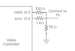
and it takes in the video signal and sync signal so that it makes the sync level to 0 volts, black level to 0.3 volts and white level to 1.0 volt, and then output it to the TV.
The audio controller output connects to a low pass filter with time constant 0.1 ms:
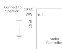
The low pass filter has a 10K ohm resistor and a 10nF capacitor. The LPF makes the audio sounds smoothy and less noisy.
The keypads are connected to PORTA and PORTB. The connection details are shown in lab2:
http://people.ece.cornell.edu/land/courses/ece4760/labs/s2012/lab2.html
The communication buses are 8-bit, plus a shared ground. Between the connection of each port and ground, there is a 1K ohm resistor between each connection pin. This is to protect spikes from a unit when another unit turns on.
Results
The game performed up to expectations, with I/O behaving quite responsively.
In our testing, we could fire missiles or enter controls as fast as physically
possible and did not detect any noticeable latency between user input and
graphical or audio response. In our testing we noticed some minor graphical
inconsistencies when both players fired missiles as rapidly as possible, though
the bug was inconsistent. It is possible that there are concurrency issues that
arise when an interrupt triggers as a graphical update is done, but this only
occurs with a large number of sprites on screen, as otherwise the graphical
update function has already completed before the next interrupt.
Unfortunately, due to the graphical nature of this game, there were no special considerations made for people with disabilities.
The video controller runs at 16MHz and refresh the screen at 60Hz. The timing of the video is accurate so we can see the video display smoothly. The data memory is 90.1% full and the CPU uses abou 77% of time to update the screen on TV.
The audio controller has an accurate frequency and we can hear all music on scale. The sounds are sampled at 8KHz and the sound quality is good enough. The music with multiple layers work well and the sound effect added does not disturb the background music. All audio element works well together. The peak usage of audio controller CPU is about 60% and the data memory is 57.8% full.
Here is the game video on Youtube:
Conclusion
Our initial plan consisted of emulating an entire GameBoy system using Mega644 microcontrollers. However, a few weeks into the project, we realized that this goal was infeasible, and scaled down our project to implement a simple game consisting of user input, graphics, and sound. In this context, the results of the project did not meet our initial lofty expectations, though we are still happy with our end result. If we were to do this project again, we would have set more realistic expectations, as we were warned by Bruce Land that it would be very difficult to accomplish our initial goal (he also commented that previous groups that tried similar projects had some difficulties with their projects).
Intellectual Property and other Legal considerations
The debounce logic used for user input in the game code is directly derived from Bruce Land's example debounce code given in Lab 1 of ECE4760: The audio controller code is adapted and modified from the codes provided by the course ECE4760 website: http://people.ece.cornell.edu/land/courses/ece4760/labs/s2012/lab1.html
FM: http://people.ece.cornell.edu/land/courses/ece4760/Math/GCC644/FM_synth/FM_synth_1.c
DPCM: http://people.ece.cornell.edu/land/courses/ece4760/Speech/GCC644/speech_644_GCC.c
The matlab program used to generate the sound effects:
http://people.ece.cornell.edu/land/courses/ece4760/Speech/GCC644/Speech_encode_GCC.m
We did not reverse engineer any product, and did not sign any NDAs for equipment. In addition, we do not forsee any patent or publishing opportunities for this project. Due to the simplicity of the game, there may or may not have been patents on similar game mechanics in the past. However, due to the simple nature of the game, we believe this is fair use and do not forsee any issues. The game music is coded from some existing pieces of music. Since this project is only for educational purposes and we only took a small portion of the music, it is considered a fair use to use the music and the "battle city" game.
Ethical Considerations
During this project, we were sure to to follow safety protocols involving ourselves and other people. Safety equipment was used for all hardware design, such as soldering circuits, and we were sure not to endanger others with our actions. No conflicts of interest occured during the project involving other groups, and if there were we would have disclosed the issues. In no case were we offered bribes or related compensation for actions, and we would have rejected the offer and reported the incident if it had occured. The project was chosen because of its ability to combine a great deal of material that we had learned over the course, synthesizing various aspects of software design (such as audio synthesis), and hardware design (our processor circuits) in order to give us more experience in the creation and maintenance of complex projects.
In no way in the completion of this project did we discriminate against others based on their race, religion, gender, disability, nationality, or age, and we did not maliciously or intentionally harm others. In addition, we were willing to listen to criticism and assistance from others helping us, and helped other groups whenver needed.
Appendix I Program Listing
Game: game.c
Video controller: video_controller.c
Audio controller: audio_controller.c; audio.h; shot.h (shot fire sound effect encoded); bomb.h (bomb sound effect encoded)
Appendix II Schematics
Appendix III Budget
STK 500: $15
Small solder board: $1*3= $3
Power supply: $5*3=$15
Custom PC Board: $4*2=$8
Mega644: $6*2=$12
Keypad: $6*2=$12
B/W TV $5
Header socket: $0.05*40=$2
DIP socket: $0.05*2 = $0.1
Total: $72.1
Appendix IV Member tasks
Miao Wang: Designed the game interface game.c
Zhouheng Zhuang: Built the hardware and designed the audio controller and parts of video controller like polling and command logic.
Bojiong Ni: Designed parts of the video controller such as the draw object function and designed the webpage.
Appendix V Reference
Code adapted:
Debounce: http://people.ece.cornell.edu/land/courses/ece4760/labs/s2012/lab2code/debounceGCC644.c
FM: http://people.ece.cornell.edu/land/courses/ece4760/Math/GCC644/FM_synth/FM_synth_1.c
DPCM: http://people.ece.cornell.edu/land/courses/ece4760/Speech/GCC644/speech_644_GCC.c
The matlab program used to generate the sound effects:
http://people.ece.cornell.edu/land/courses/ece4760/Speech/GCC644/Speech_encode_GCC.m
Instructions and papers:
Keypad: http://people.ece.cornell.edu/land/courses/ece4760/labs/s2012/lab2.html
Video Generation: http://people.ece.cornell.edu/land/courses/ece4760/video/index.html
Speech Generation: http://people.ece.cornell.edu/land/courses/ece4760/video/index.html
Audio Synthesis: http://people.ece.cornell.edu/land/courses/ece4760/labs/s2012/lab3.html
Music Frequencies: http://www.phy.mtu.edu/~suits/notefreqs.html
Synthesis of Musical Notes and Instrument Sounds with Sinusoids http://web.eecs.utk.edu/~qi/ece505/project/proj1.pdf
About Battle City game: http://en.wikipedia.org/wiki/Battle_City_(video_game)
Data Sheet:
Music samples:
Battle City start music: http://www.youtube.com/watch?v=iZcpbxtYmD0
Mario: http://www.youtube.com/watch?v=O63XYq0Nmpg
Pokemon: http://www.youtube.com/watch?v=f8MHSO7Hat8
James Bond: http://www.onlinesheetmusic.com/the-james-bond-theme-p95947.aspx
Appendix VI Music Properties
| Note | Frequency |
| c4 | 261.63 |
| c4# | 277.18 |
| d4 | 293.66 |
| d4# | 311.13 |
| e4 | 329.63 |
| f4 | 349.23 |
| f4# | 369.99 |
| g4 | 392 |
| g4# | 415.3 |
| a4 | 440 |
| a4# | 466.16 |
| b4 | 493.88 |
| c5 | 523.25 |
| c5# | 554.37 |
| d5 | 587.33 |
| d5# | 622.25 |
| e5 | 659.26 |
| f5 | 698.46 |
| f5# | 739.99 |
| g5 | 783.99 |
| g5# | 830.61 |
| a5 | 880 |
| a5# | 932.33 |
| b5 | 987.77 |
| c6 | 1046.5 |
| c6# | 1108.73 |
| d6 | 1174.66 |
| d6# | 1244.51 |
| e6 | 1318.51 |
| f6 | 1396.91 |
| f6# | 1479.98 |
| g6 | 1567.98 |
Acknowledgement
Thanks Bruce and ECE 4760 TAs for their kindly help on our project.