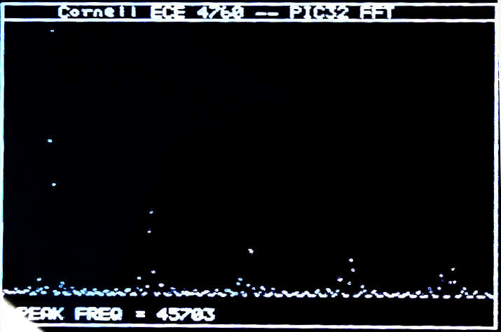
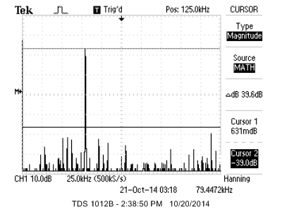
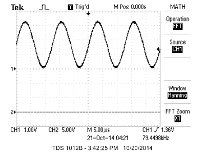
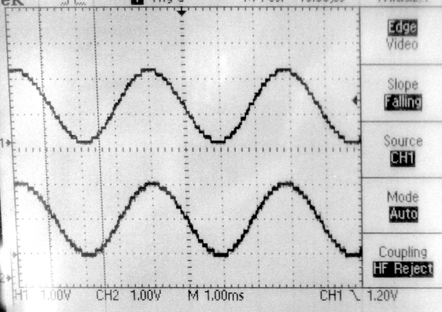
The TV framework described below was used as a spectrum analyser by adding a fixed point FFT routine. The routine works in 16:16 fixed format. A 512 point complex FFT takes 410,000 cpu cycles (with no optimization) or about 6.8 milliseconds. If we include the time to Hanning window the signal and compute the magnitude of the complex output, the process takes 454,800 cpu cycles (with no optimization), or about 7.6 milliseconds. Running the compiler at optimization level 1 (highest free compiler level) reduces the number of cpu cycles to 146,000, or about 2.4 milliseconds for Hanning-FFT-magnutude calculation. The two images show a sine signal and a square wave captured at 900,000 samples/sec. There is some aliasing of the square wave so the peaks are not clean, but you can see the 1/f spectrum. The magnitude of the FFT is approximated as
|amplitude|=max(|Re|,|Im|)+0.4*min(|Re|,|Im|). This approximation is accurate within about 4%.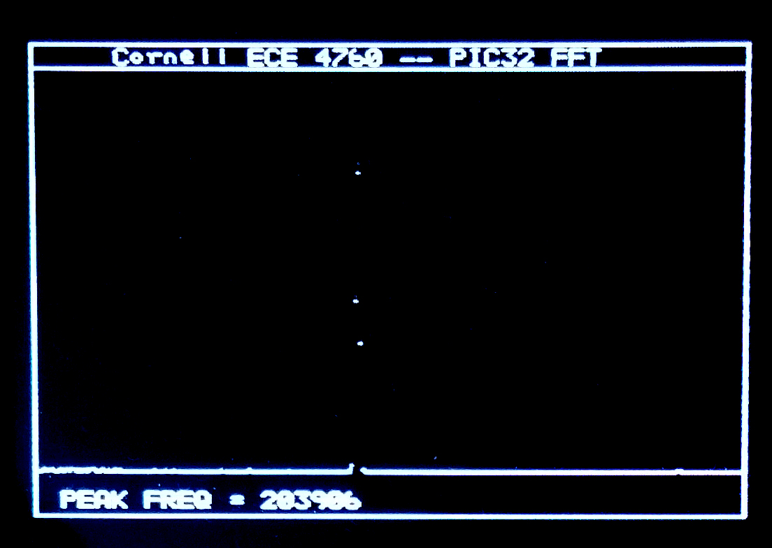
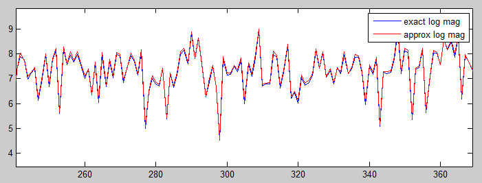
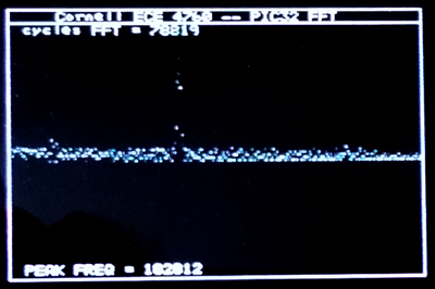
Taking the log of the magnitude using a fast approximation (Generation of Products and Quotients Using Approximate Binary Logarithms for Digital Filtering Applications, IEEE Transactions on Computers 1970 vol.19 Issue No.02) gives more resolution at lower amplitudes( code). Evaluation of the algorithm as a matlab program is here. The following images give the matlab comparison of exact and approximate log for noise, and a sinewave FFT on the PIC32.
All of the following examples use Protothreads. This means that you need the pt_cornell.h file described below. PIC architecture separates timers, from compare units and from input capture. This means that one timer can drive several output compare units for waveform generation, or act as a time reference for several input compare units. In all the examples, the cpu is running at 64 MHz and the peripherial bus at 32 MHz.
-- This example sets up timer2 to drive two pulse trains from OC2 and OC3. Either of these pulse trains can be hooked to an input capture unit, which uses timer3 as a time reference. Timer three is set up to overflow so that periods are correct when computed from sequential edge capture times. The print thread prints out the generated interval, and the min, max and current value of the captured interval. The command thread listens for user input to set the timer2 period, and a one second clock thread gives system time (using timer5, as explained below in the protothreads section). To run this, download pt_cornell.h and the example code.
-- Example 2 sets up OC3 as a PWM unit with settable timer2 period (and thus PWM resolution) and settable PWM on-time. The on-time is then auto incremented in the timer2 ISR to sweep the on-time from zero to the timer2 period. Setting the timer2 period and OC2 pulse period in the user interface thread is cleaner.
-- Example 3 sets up OC3 as a PWM unit with timer2 period (and thus PWM resolution) equal to 64 cycles (500 kHz). PWM on-time is set by a sine wave Direct Digital Synthesis (DDS) unit. The frequency synthesized is set by the UART user interface. The PWM output (Pin 18) must be passed through an analog lowpass filter. Choose the time constant of the filter consistent with the frequencies you wish to generate. Spectral purity is about 32 db at low frequencies. You could get better spectral purity by increasing the PWM resolution, but that, of course, lowers the sample rate. Eight-bit samples have a PWM sample rate of 125 kHz.
Generating a good sine wave requires a high sample rate, and reasonable accuracy DAC. A DMA channel is used to blast a sine wave (or any other periodic function) out of port B.0 to B.5 and B.7. (Note that B.4 and B.5 have a required config statement to turn off JTAG and clock input and that B.6 does not exist on this package). On a PIC32 running at 60 MHz, the DMA channel can support about 3.5 million bytes/sec in single byte transfer mode triggered by a timer (but with no ISR). The useful frequency range is 10 Hz to 200 KHz. During synthesis, NO cpu cycles are used. The sine table is dynamically sized according to the frequency range to minimize distortion. The sine wave delivered has the highest amplitude error harmonic about 40 db below the fundamental up to 100 KHz and less than 35 db above that frequency. Code is here. Spectrum and waveform of a nominal 80 KHz signal is below.
Protothreads is a very light-weight, stackless, threading library written entirely as C macros by Adam Dunkels. As such, it is trivial to move to PIC32. Adam Dunkels' documentation is very good and easy to understand. There is support for a thread to wait for an event, spawn a thread, and use semaphores. The Protothreads system is a cooperative multithread system. As such, there is no thread preemption. All thread switching is at explicit wait or yield statement. There is no scheduler. You can write your own, or just use a simple round-robin scheme, calling each thread in succession in
main.
Because there is no preemption, handling shared variables is easier because you always know exactly when a thread switch will occur. Because there is no separate stack for each thread, the memory footprint is quite small, but using automatic (stack) local variables must be avoided. You can use static local variables. Protothreads uses a switch-statement type construct to handle thread switching, so it is not possible to embed a thread-wait statement in a switch stanza.
You must read sections 1.3-1.6 of the reference manual to see all of the implementation details.
I hacked some of Dunkels' examples shown below and added:
- A millisecond resolution time thread yield macro
- Nonblocking UART receive thread
- Nonblocking DMA UART transmit thread
- A UART terminal command interpreter
- A simple rate scheduler that allows some threads more cpu time than others
- A 1-pin event debugger using the settable voltage reference pin.
Current Version:
To run protothreads you need to download pt_cornell.h. The Example1 test code also requires a UART connection to a terminal, as explained in a project further down the page. The test code toggles three i/o pins and supports a small user interface through the UART.It also emits three different amplitude debugging pulses on pin 25. By default this version of protothreads starts 32-bit timer45 and uses a timer ISR to count milliseconds. The following table has the protothread macro extensions and functions I wrote for the PIC32 and which are included in the header file..
Protothreads function |
Description
|
|---|---|
PT_YIELD_TIME_msec(delay_time) |
Causes the current thread to yield (stop executing) for the delay_time in milliseconds. The time is derived from a 1 mSec ISR running from timer5. |
PT_GET_TIME() |
Returns the current millisecond count since boot time. Overflows in about 5 weeks. The time is derived from a 1 mSec ISR running from timer5. |
PT_RATE_INIT() |
Sets up variables for the optional rate scheduler |
PT_RATE_LOOP() |
House keeping for the optional rate scheduler |
PT_RATE_SCHEDULE(f,rate) |
For thread f, set the rate=0 to execute always, rate=1 to execute every other traversal for PT_RATE_LOOP, rate=2 to every fourth traversal, rate=3 to every 8th, and rate=4 to every 16th. |
PT_DEBUG_VALUE(level, duration) |
Causes a voltage level from 0 to 15 (1 implies ~150 mV) to appear at pin 25 (CVrefOut) for duration microseconds (approximately). Zero duration means hold the voltage until changed by another call. |
int PT_GetSerialBuffer(struct pt *pt) |
A thread which is spawned to get nonblocking string input from UART2. String is returned in char PT_term_buffer[max_chars]. If more than one thread can spawn this thread, then there must be semaphore protection. Control returns to the scheduler after every character is received. The thread dies when it recieves an <enter> |
int PutSerialBuffer(struct pt *pt) |
A thread which is spawned to send a string input from UART2. String to be sent is inchar PT_send_buffer[max_chars]. If more than one thread can spawn this thread, then there must be semaphore protection. Control returns to the scheduler after every character is loaded to be sent. The thread dies after it sends the entire string. |
int PT_DMA_PutSerialBuffer(struct pt *pt) |
A thread which is spawned to send a string input from UART2. String to be sent is inchar PT_send_buffer[max_chars]. If more than one thread can spawn this thread, then there must be semaphore protection. Control returns to the scheduler immediately. The thread dies after it sends the entire string. |
void PT_setup (void) |
Configures system frequency, UART2, a DMA channel 1 for the UART2 send, timer5, and the debug pin Vref controller. |
=============================
To run these older examples you need to download software from Dunkels' site or use a local copy. Most examples also require a UART connection to a terminal, as explained in a project further down the page.
Older examples:
-- The first example has two threads executing at a rate based on a hardware timer ISR, which generates a millisecond time counter. Each thread yields for a waiting time and when executing prints the thread number and time. Thread 1 executes once per second. Thread 2 executes every 4 seconds. Main just sets up the timer ISR and UART, then inintialzes the threads and schedules them.
-- The second example has three threads. Threads 1 and 2 wait on semaphores, each of which is signaled by the other thread. The two threades therefore alternate. Thread 3 just executes every few seconds. I defined an new macro to make it easier for a thread to wait for a specific time.
PT_YIELD_TIME(wait_time) takes the wait time parameter and uses a local variable and the millisceond timer variable to yield the processor to another thread for wait_time milliseconds. The second example also has a small routine to compute approximate microseconds since reset and return it as a 64-bit long long int.
#define PT_YIELD_TIME(delay_time) \
    do { static int time_thread; \
    PT_YIELD_UNTIL(pt, milliSec >= time_thread); \
    time_thread = milliSec + delay_time ;} while(0);
-- The third example has three threads.
Threads 1 and 2 wait on semaphores, each of which is signaled by the other thread. The two threads therefore alternate. Thread 3 takes input from a serial terminal. The actual input routine is a thread which is spawned by thread 3.
Thread 3 then waits for the input thread to terminate which it does when the human presses <enter>. The input thread yields the processor while it is waiting for the slow human to type each character, so other threads do not stall. The key statment is below which causes protothreads to wait/yield on a hardware flag.
The flag is defined as part of plib.h.
PT_YIELD_UNTIL(pt, UARTReceivedDataIsAvailable(UART2));
Note that the spawn command
PT_SPAWN(pt, &pt_input, GetSerialBuffer(&pt_input) );
initializes the input thread
and schedules it. The three parameters are the current thread structure, a pointer to the spawned thread, and the actual thread function. If more than one thread is using serial input, then the spawn command should be surrounded by semaphore wait/signal commands because GetSerialBuffer is not reentrant.
-- The fourth example investigates non-blocking UART transmit. In a printf, there is a waitloop for each character. We can replace that with thread yield on a per character basis. Doing this speeds up processing a factor of 2 or so. But how fast is the swtich between two threads? Is it worth a thread yield on every character? Commenting out all UART code and just waiting/signaling on a semaphore between thread 1 and thread 2 gives a switch time between threads (twice) of 2.1 microcseconds or about 126 cpu cycles. This value includes the signaling, waiting, and thread switch code two times (thread 1 to thread 2 and back). For a 1 mSec charcter transmit time, the thread switch is worth the overhead.
-- The fifth example implements a terminal command interface in thread 3 using non-blocking UART send/receive.
Thread 1 and 2 toggle and are dependent upon signalling each other unless turned off by a flag from the interactive input. . Thread 4 just toggles at a fixed rate, unless it is turned off by the interactive input, working through the scheduler. The code assumes that port pins B0, A0, and A1 are connected to LEDs (with 300 ohm resistor to ground).
Hitting the <enter> key to finish a command results in a 9 microSec pause in the toggling of the other threads.
There are 8 commands:
| command | effect |
t1 time |
sets blink rate of thread 1/2 to time |
t2 time |
sets blink rate of thread 4 to time |
g1 |
starts thread 1/2 blink |
s1 |
stops thread 1/2 blink |
g2 |
starts thread 4 blink |
s2 |
stops thread 4 blink |
k |
kills the interactive input until RESET |
p |
prints the current blink times |
-- The sixth example runs the same interface as example five, but uses a DMA
channel to drive the UART output with no software overhead. The DMA pattern matching feature detects the end of a string to stop the UART automatically.
Using the DMA transfer allows a per-string thread yield, rather than a per-character thread yield. The code assumes that port pins B0, A0, and A1 are connected to LEDs (with 300 ohm resistor to ground). The thread switch after hitting <enter> now takes 5 microSec. With both t1 and t2 set to 1 milliSec, the dispersion in actual times for both is less than 10 microSec (<1%).
-- The seventh example adds a microsecond resolution yield option. The option is marginally useful down to about 10 microseconds, where the timing uncertainty reaches about 10%. At 100 microseconds the accuracy is good. This means that you could attempt audio synthesis in a thread at 10 KHz sample rate. Thread 4 is timed by the microsecond timer. With three threads running below100 microSec repeat rate, the system starts to miss events. The previous PT_YIELD_TIME macro has been replaced by two. One for millisecond timing and one for microsecond timing. The millisecond timer overflows about once/month. The microsecond timer overflows every 64 milliseconds. The maximum time delay using the microsecond timer is 64000 microseconds.
// macro to time a thread execution interval
#define PT_YIELD_TIME_msec(delay_time) \
    do { static int time_thread; \
    time_thread = milliSec + delay_time ; \
    PT_YIELD_UNTIL(pt, milliSec >= time_thread); \
    } while(0);
// macro to time a thread execution interveal
// parameter is in MICROSEC < 64000
//ReadTimer2()
#define PT_YIELD_TIME_usec(delay_time) \
    do { static unsigned int time_thread, T3, c ; \
      time_thread = T3 + delay_time ; c = 0;\
      if(time_thread >= 0xffff) { c = 0xffff-T3; }\
      PT_YIELD_UNTIL(pt, ((ReadTimer3()+c)& 0xffff) >= ((time_thread+c) & 0xffff)); \
      T3 = ReadTimer3() ;\
    } while(0);
-- The eighth example introduces a minimal scheduler which allows each thread to execute at a rate determined as a fraction of full speed. The default protothreads thread swap is so fast that it a challange to introduce scheduling which does not slow down thread execution rates. The approach taken is to allow some threads to execute every time through the main while-loop, but allow others to only execute at 1/2, 1/4, 1/8, or 1/16 of the times through the main loop. The approach is consistent with a nonpremptive thread system and gives better execution consistency if one thread has to execute at a much higher rate than the others. Rate 0 executes every time throught the loop, rate 1 every other time, 2 every four times, rate 3 every 8 times, and rate 4 every 16 times through the main while-loop. Any other value freezes the thread execution. With thread 4 executing at a nominal 10 microSec period, the actual time varys from 11 to 13 microSec, but the actual time can vary widely depending on the exact interval picked due to coincidence with other processes. This version also fixes the microsecond timer by using timer45 as a 32-bit counter.
-- Finally we get to something like a final version of the code.
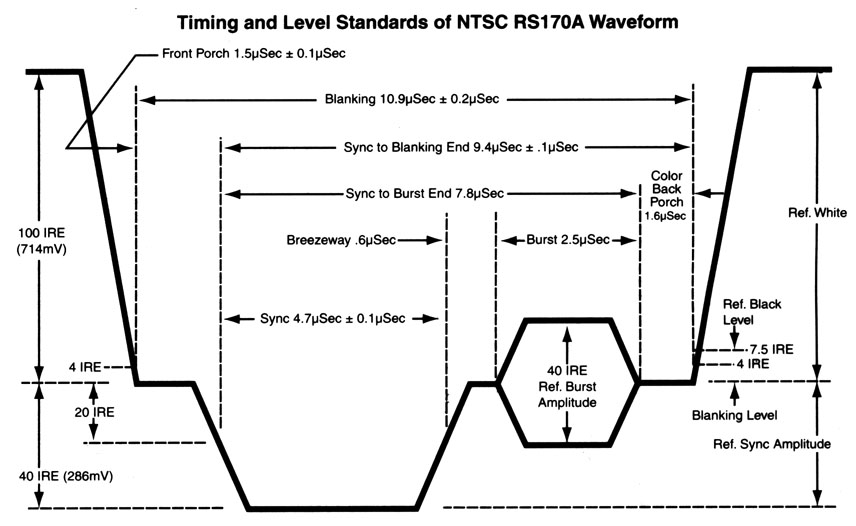
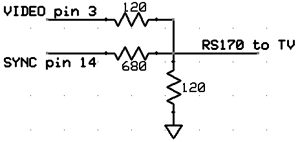
--NTSC video is an old standard, but is still used in North America for closed circuit TV. It is fairly simple to generate a black/white NTSC signal. Also, the frame buffer for a 1-bit, 256x200 pixel image is only 1600 words (6400 bytes) of RAM. Chapter 13 of Programming 32-bit Microcontrollers in C: Exploring the PIC32 by Lucio Di Jasio was very useful. I used Di Jasio's method of generating sync pulses using one output-compare unit. Video is sent to the SPI controller using DMA bursts from memory (also similar to Di Jasio), but DMA timing-start control was implemented using another output-compare unit rather than chaining two DMA channels. This allowed easy control of video content timing. Timer2 is ticking away with an match time equal to one video line time. Ouput-compare 2 is slaved to timer2 to generate a series of pulses at the line-rate. The duration of the OC2 pulses (for vertical sync) is controlled by the Timer2 match ISR in which a simple state machine is running, but the pulse durations are not dependent on ISR execution time. Output-compare 3 is also slaved to timer2 and set up to generate an interrupt at a time appropriate for the end of the NTSC back porch, at which time the DMA burst to the SPI port starts. I got best video stability when the core is running at 60 MHz and the peripheral bus running at 30 MHz. The first example is just a bounding ball with some text. The example requires that the ascii character header file be in the project folder. The DAC which combines the SYNC and video signal and adjusts to levels to standard video is:
--The second example is a particle system explosion. Without doing any space optimization 1500 particles (along with screen buffer) use up memory. All the positions can be updated in every frame. Giving each particle a high initial velocity, and high drag makes a nice cloud.
-- The third example is a particle system fountain, which is a slight modification of the explosion. I optimized the point-draw and one ISR for more efficient execution. Frame update now takes 7.2 mSec. Video. The overhead for NTSC TV signal generation is about 5 microSec per 63.5 microSec line, or about 8%. You should use this optimized version for an intensive animation. A small variation makes the particle system fire to the side. Video.
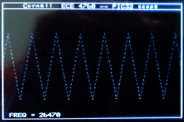
--The fourth example turns on the ADC to make an oscilloscope. The ADC is set up to trigger from the timer3 compare match signal, but without turning on an ISR. A DMA channel transfer is then triggered by the ADC done signal to dump the ADC results to memory at up to 900 Ksamples/sec. This ADC hardware process runs at the same time as the video update hardware process, so video is not disturbed. CPU load is small so there is time to draw the ADC waveform to the screen. It would be straightforward to add a button state machine for scope control and a FFT. The following image is captured from the NTSC screen and shows the scope running at 900 Ksamples/sec and displaying a frequency estimate. Video is running at 500 Ksamples/sec ADC rate.
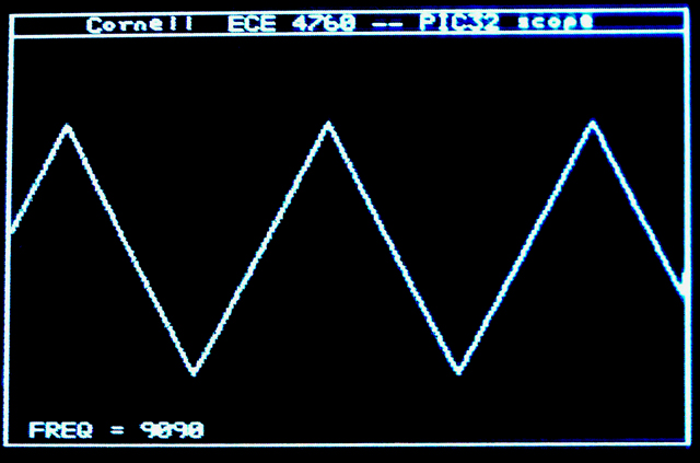
-- The fifth example is a vector variation of the scope. Drawing all the vectors slows the redraw down so that the scope is updated 30 times/sec.
Video is running at 900 Ksamples/sec. Still image below.
-- It is useful to get a serial channel running for fairly high speed peripherials. The first device I tried is an Analog Devices AD7303. It is a two channel, 8-bit DAC with buffered voltage output. The channels may be updated simultaneously or separately. Each channel write requires a two-byte transfer to the DAC. The first is a control byte, and the second is the channel data byte. The control byte specifies which channel will be updated as well as the update mode. Each two-byte transfer must be signaled by dropping the voltage on a SYNC pin before the beginning of the transfer, then raising it at the end. Like most microcontrollers the PIC32 SPI interface is simple enough to handle that direct register manipulation is probably the easiest, although the higher level
SpiChnOpen function also worked well. The SPI standard supports four clock phases. The microconctoller master has to match the requirements of the slave. This is often the most annoying part of getting SPI running. Careful analysis of the slave datasheet is required. The AD7303 requires the slave to generate a clock frequency less than 30 MHz, and expects the data to be stable on the the positive clock edge. The required configuration is SpiChnOpen(spiChn, SPI_OPEN_ON | SPI_OPEN_MODE16 | SPI_OPEN_MSTEN | SPI_OPEN_CKE_REV | SPI_OPEN_CKP_HIGH , spiClkDiv);or equivalently:
SPI1CON = 0x8560 ; // SPI on, 16-bit, master, CKE=1, CKP=1

      //The SPI baudrate BR is given by: BR=Fpb/(2*(SPI1BRG+1))

      SPI1BRG = 0;  // Fperipheralbus/2
The basic SPI transaction is to start a simultaneous send/receive. On the DAC used here, no useful data is received, but you must do the receive operation to reset the
SPI1STATbits.SPIRBF flag. For this application the SPI transaction ismPORTBClearBits(BIT_0); // start transaction
SPI1BUF = DAC_cntl_1 | DAC_value ; // write to SPI
while( !SPI1STATbits.SPIRBF); // check for complete transmit
junk = SPI1BUF ; // read the received value (not used by DAC in this example)
mPORTBSetBits(BIT_0); // end transaction You clear the SYNC bit, write to SPI1BUF to trigger the hardware trnasmit/receive, wait for it to finish, then do the manditory read and set the SYNC bit. Connections between the two devices are shown below, assuming a certain PPS setup as shown in the code.
| AD7303 | PIC32 |
| SCLK | SCK1 is pin 25 |
| DIN | SDO1 is PPS group 2, map to RPA1 (pin 3) |
| ~SYNC | PortB.0 (pin 4) |
| not used | SDI1 is PPS group 2, map to RPB8 (pin 17) |
In addition to the SPI protocol, each different device you attach to the SPI bus has a command syntax which is specific to the device. In this case, the first byte transmitted has the following bit definitions, while the second byte represents the voltage output in straight binary, where binary zero outputs zero volts and binary 0xff outputs Vref..
bit 7 notINT/EXT set to notINT = 0. Use internal Vref

      bit 6 = 0 (not used)

      bit 5 LDAC load and update both channels when set

      bit 4 PDB = 0 pwer down channel B

      bit 3 PDA = 0 pwer down channel A

      bit 2 notA/B = 0 chooses A

      bit 1 CR1=0  control bits modify load mode

      bit 0 CR0=1  set to load A from SR
The actual commands I used here:
Command: Load A from shift register:
DAC_cntl_1 = 0b00000001 ;Command : Load B from SR and and update both outputs:
DAC_cntl_2 = 0b00100100 ;
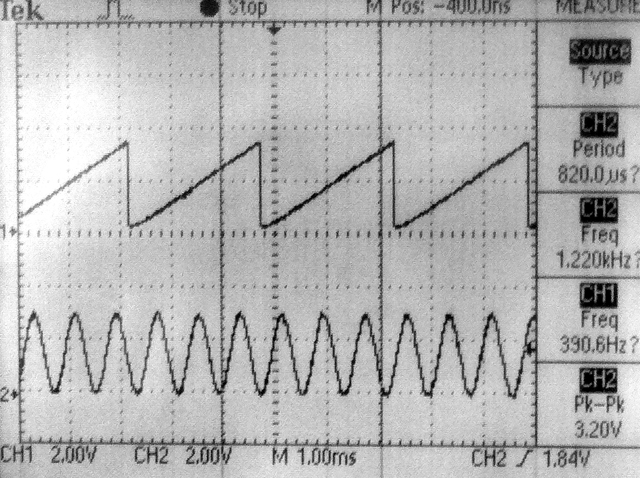
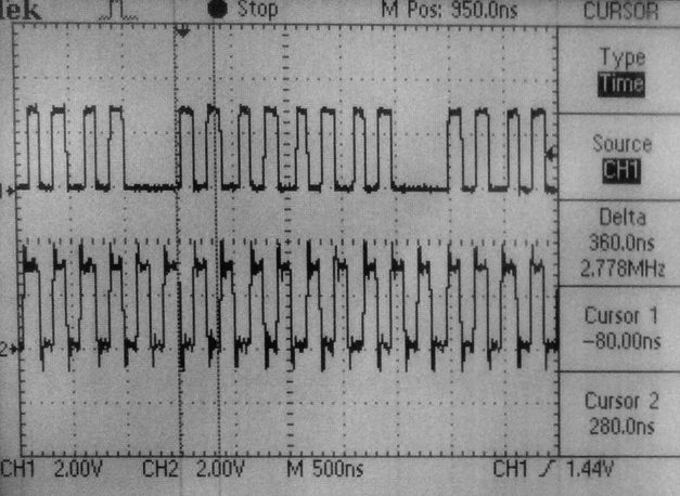
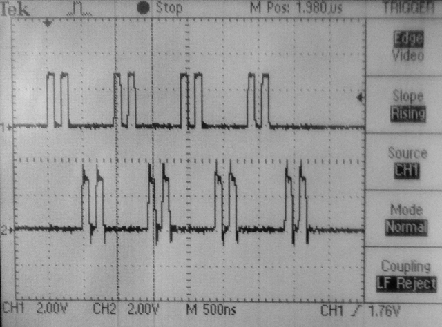
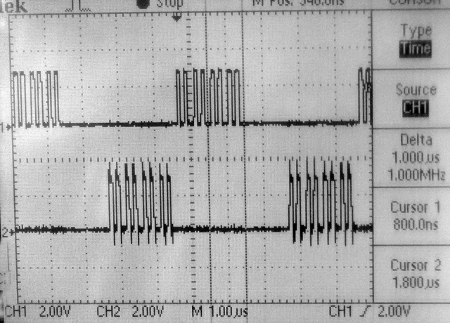
The following image
shows the SYNC on the top trace and the SCK1 on the bottom trace. The core frequency and peripheral bus frequency are set 40 mHz. The SCK1 is running at Fpb/2=20 MHz. The total transaction time for the two channels is 2.6 microSec. The second image shows the DAC outputing a DDS sawtooth on one channel and the ADC input on the other at a sampling rate of 100 KHz. Setting the core and peripheral bus to 60 MHz runs the AD7303 at its maximum bus speed and drops the total time to transmit one 16-bit transaction to 850 nS and both channels to 1.75 microSec. The code in the ISR was arranged so that all ISR housekeeping is being done while the SPI hardware does the transmit.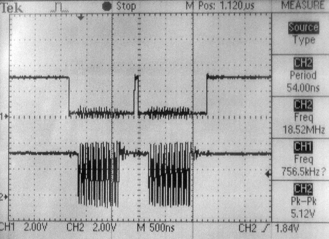
I decided to start by implementing Butterworth IIR filters using the fixed point formats below. The first step is to find out how much the limited precision arithmetic will affect the filters. I am not using the PIC32 DSP ligrary because I could not figure out the format for the constants. Filters are implemented as unfactored first or second order Direct forms or as second order sections (SOS) which take a scale factor input as well as two a-vector values. For Butterworth, the b-vector is fixed (refer to Matlab or Octave
butter function). This matlab program allows you to check SOS filter response accuracy for a given bandwidth. This program uses an unfactored IIR filter design for comparision. For low-order filters (one or two samples), unfactored IIR filters will be faster, while being accurate enough. -- A one-sample (RC type) lowpass filter executes in 89 cycles on the PIC32 as shown in this C program. The filter uses an array for the filter coefficients and another for the filter history. Inserting this filter into the ADC-to-DAC code in a section below results in a program in which the ISR samples the ADC, filters, scales and outputs to the DAC in 2.7 microseconds, including ISR overhead (60 MHz core clock). In this code, the sample rate Fs=100 kHz, the filter cutoff is 0.01/(Fs/2)=500 Hz. Actual cutoff measured in 490 Hz. This filter has less than 1% error above a cutoff=0.002.
// coeff = {b2, -a2} noting that b1=b2 and a1=1 (for first order Butterworth)
// history = { last_input, last_output}
fix16 coeff[2], history[2], output, input ;
fix16 IIR_butter_1_16(fix16 input, fix16 *coeff, fix16 *history )
{
    fix16 output;
    output = multfix16(input+history[0], coeff[0]) + multfix16(history[1], coeff[1]) ;
    history[0] = input ;
    history[1] = output ;
    return output ;
}
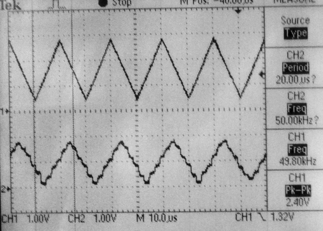
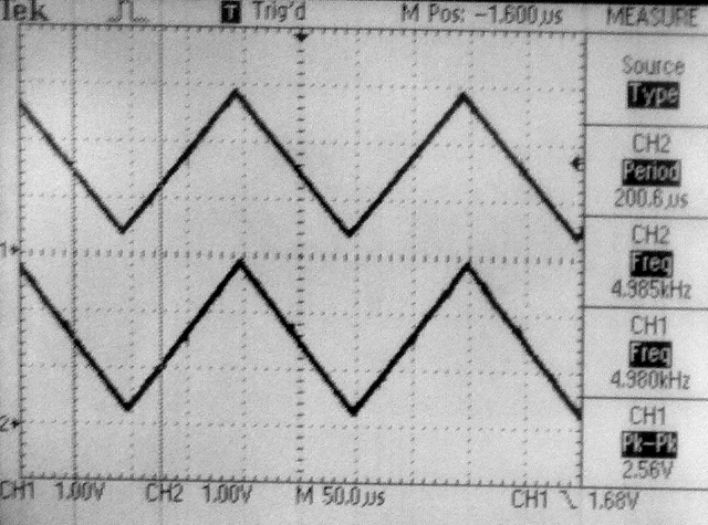
-- A second order Butterworth lowpass has less than 1% response error down to cutoff=0.04. At cutoff=0.1 (and Fs=100 kHz) the measured cutoff frequency is very close to 5 kHz, as predicted. The ISR takes 3.5 microSec to execute (60 MHz core clock). -- A second order Butterworth bandpass can be set down to a bandwidth of about 0.003 with less than 1% error. At cutoff=[0.1, 0.11] (and Fs=100 kHz) the measured peask response is 5.25 kHz and the cutoffs are at 4.98 and 5.5 kHz, as predicted. Tthe DC component of the input is removed by the highpass characteristic of the filter, so a DC correction has to be made because the DAC can only produce a positive voltage. In the ISR, 128 is added to the 8 bit DAC value
DAC_value = (output>>6) + 128 ;.-- A generalized SOS Butterworth lowpass executes in 7.5 microSec (ISR, 60 MHz core clock, 4-pole). The 4-pole version with a cutoff=0.1 has the predicted resopnses near the cutoff frequency and where the response drops to 0.1 of peak. Six-pole takes 10 microSec, 8-pole takes 12.5 microSec. The sample frequency is set to 20 kHz. This matlab program computes the filter parameters for SOS and prints C code to the matlab console window to paste into the program for both lowpass and bandpass filters.
-- A generalized SOS Butterworth bandpass filter which uses the matlab progam mentioned just above to construct parameters. The example is set to a bandwidth of 0.002, about as narrow as you can get with 2.14 format fixed coefficients.
-- The SOS filters above are easy to read, but slow to execute because of the 2D arrays. Unrolling the loops, and making all the indices constant, speeds up the filters by almost a factor of two. This program uses the UART interface to profile number of cycles to execute. Putting the revised SOS filters back into the realtime program with ADC and DAC gives an ISR time of 7.7 microSec for the 4-section, eight-pole, bandpass filter. Almost all of the time in the ISR is the filter. A reasonable rule would be 2 microSec/pole of filtering. At 8 kHz sample rate, could do about 60 poles of filtering, or about fifteen 4-pole filters.
-- Fixed point arithmetic is the first step to building DSP functions. I decided to implement 2.30 and 2.14 formats. This means two bits to the left of the binary-point, one of which is the sign bit. The dynamic range of the systems is either -2 to 2-2-14 or -2 to 2-2-30. The resolution is either 2-14=6*10-5 or 2-30=9*10-10. The resolution is necessary to make stable, accurate, filters. The dynamic range is sufficient for Butterworth, IIR filters, made with second order sections (SOS). SOS help to minimize filter roundoff errors. This program defined the data types and macros for converting float-to-fix, fix-to-float and fixed point multiply. Add and subtract just work. The program uses timer2 to count cycles to profile the time for the add and multiply operations, then uses the UART (see section below) to print the results. The 2.30 format takes 40 cycles to to a multiply-and-accumulate (MAC) operation. The 2.14 format takes 17 cycles for a MAC operation (level 0 opt). The 2.14 result (
1.5*0.05-0.25) is in error by 4*10-5, the 2.30 result is correct to 8 places. The macros for the 2.30 follow:
typedef signed int fix32 ;
#define multfix32(a,b) ((fix32)(((( signed long long)(a))*(( signed long long)(b)))>>30)) //multiply two fixed 2:30
#define float2fix32(a) ((fix32)((a)*1073741824.0)) // 2^30
#define fix2float32(a) ((float)(a)/1073741824.0)
Another fixed point system useful over a larger integer range is 16.16 format with a range of +/-32767 and a resolution of 1.5x10⁻⁵. The macros for this system are
typedef signed int fix16 ;
#define multfix16(a,b) ((fix16)(((( signed long long)(a))*(( signed long long)(b)))>>16)) //multiply two fixed 16:16
#define float2fix16(a) ((fix16)((a)*65536.0)) // 2^16
#define fix2float16(a) ((float)(a)/65536.0)
#define divfix16(a,b) ((fix16)((((signed long long)(a)<<16)/(b))))
#define sqrtfix16(a) (float2fix16(sqrt(fix2float16(a))))
The performance for operations vary. At level 1 opt, fixed multiply is about 2.4 times faster than floating point (23 cycles), and fixed add is about 8 times faster (8 cycles). However fixed divide is the same speed as float, and fixed square root is 0.6 the speed of the float operation. Test code.
-- The PIC32 has a 10-bit ADC which runs up to 1 MHz sample rate, although the first example is limited to a little more than 500kHz because sampling is controlled by an ISR (see below for interrupt perfomance). The first example samples one channel, with most ADC features disabled. The
ADC_CLK_AUTO is turned on so that conversion immediately follows sample-aqusition, but aquisition is started manually in the ISR and goes into one slot of the buffer array where it is immediately copied into the Vref DAC for output to the scope. The first image shows the signal generator input to AN4 on channel one and the limited resolution Vref DAC on channel two. The triangle wave is set to 50 kHz. Since the sampling rate is 500 kHz there are 10 samples on each cycle, probably about the limit for sampling. There appears to be about 1.5 samples of phase delay at the positive peak, but less at the negative peak because of nonlinear loading effects noted in the Vref DAC section. -- The ADC specification (search on TAD in the datasheet) says that for a low Z source (<500 ohms) the ADC bit-clock period must be >65 nSec and the ADC sample period must be >132 nSec. At peripheral bus clock of 40 MHz (period 25 nSec),
ADC_SAMPLE_TIME_6 should work for the sample period (150 nSec) and ADC_CONV_CLK_Tcy2, while a little fast (50 nSec), seems to work for the ADC clock.A safer code turns ADC_AUTO_SAMPLING_ON so that the ADC runs as fast as possible makes it possible to sample at 500 KHz using ADC_CONV_CLK_Tcy, which exceeds the minimum bit-clock period time by setting the bit sample time to 100 nSec. Hooking up a higher quality DAC
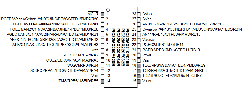
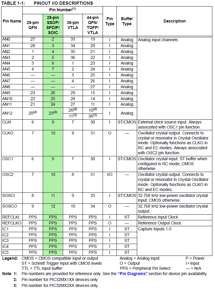
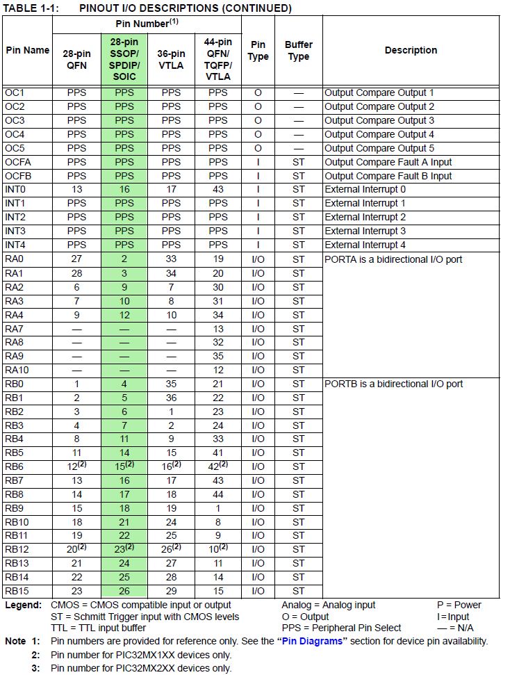
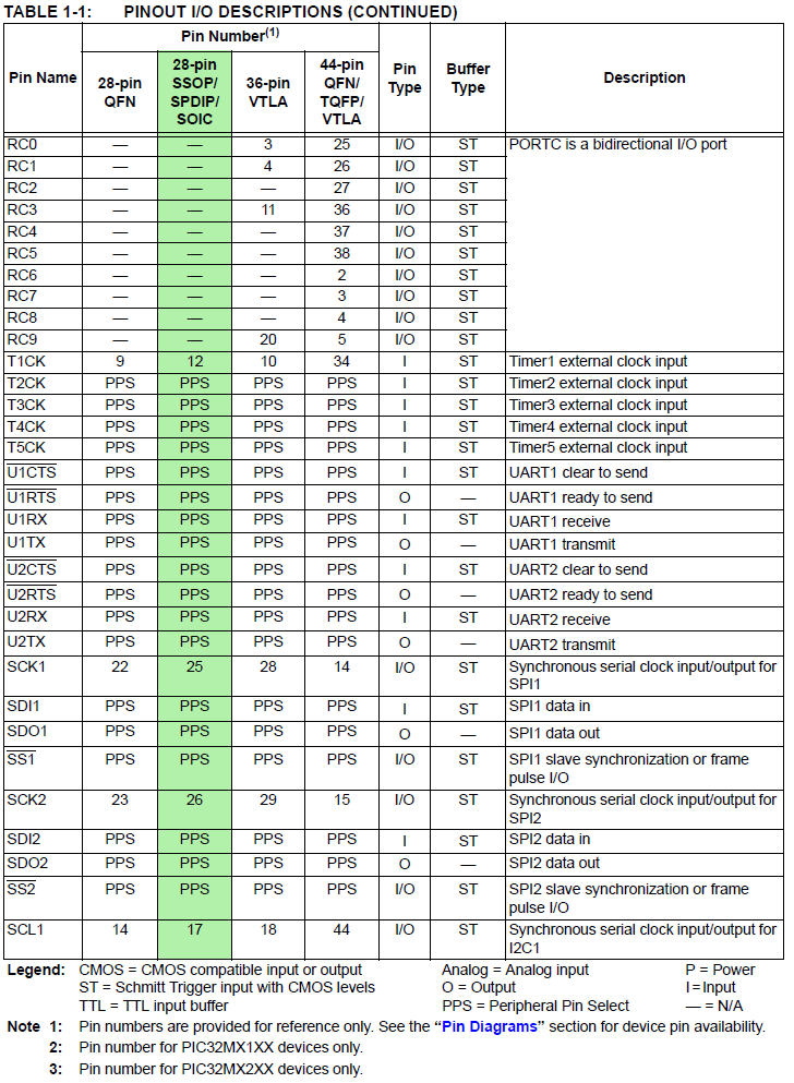
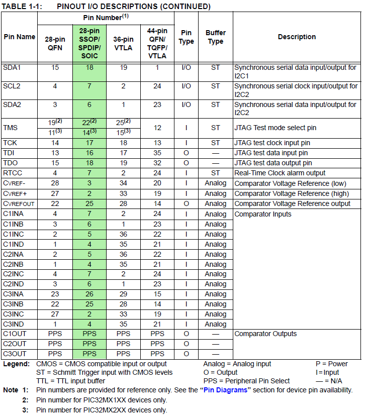
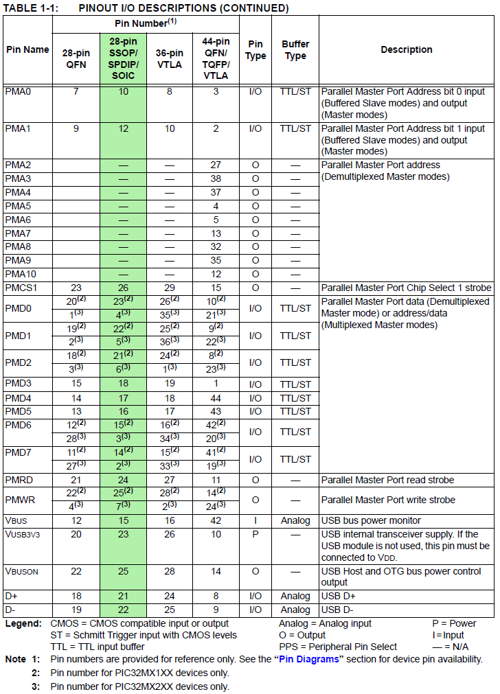
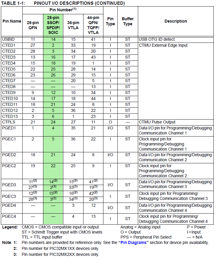
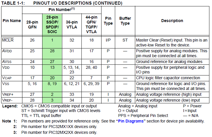
( 4116R-R2R-253LF resistor array) gives 8-bit resolution and allows accuracy testing of the ADC. The DAC resistor array is mapped to port B bits (lsb) 0-5 and bits 14 and 15 (msb). These port signals are pins (from lsb to msb) 4,5,6,7,11,14,25,26. The mapping does not use port B, bit-6 because the 28 pin PDIP package does not support it (see datasheet Table 1.1). Some care is needed to prevent the digital signals from coupling to the analog output. The second image shows the output from the 8-bit DAC on the bottom trace with small coupling artifacts near the 50% point.-- Changing the core clock to 60 MHz and the peripheral bus clock to 30 MHz allows a ADC bit-clock period of 66 nSec, exactly the minimum for the bit-clock. With
ADC_AUTO_SAMPLING_ON and with ADC_SAMPLE_TIME_5 and ADC_CONV_CLK_Tcy2 the system can sample at 750 KHz with a few cycles left over for main.Oscillator configuration:
#pragma config FNOSC = FRCPLL, POSCMOD = HS, FPLLIDIV = DIV_2, FPLLMUL = MUL_15, FPBDIV = DIV_2, FPLLODIV = DIV_1
#pragma config FWDTEN = OFF
#pragma config FSOSCEN = OFF, JTAGEN = OFF
// core frequency we're running at // peripherals at 30 MHz
#define	SYS_FREQ 60000000
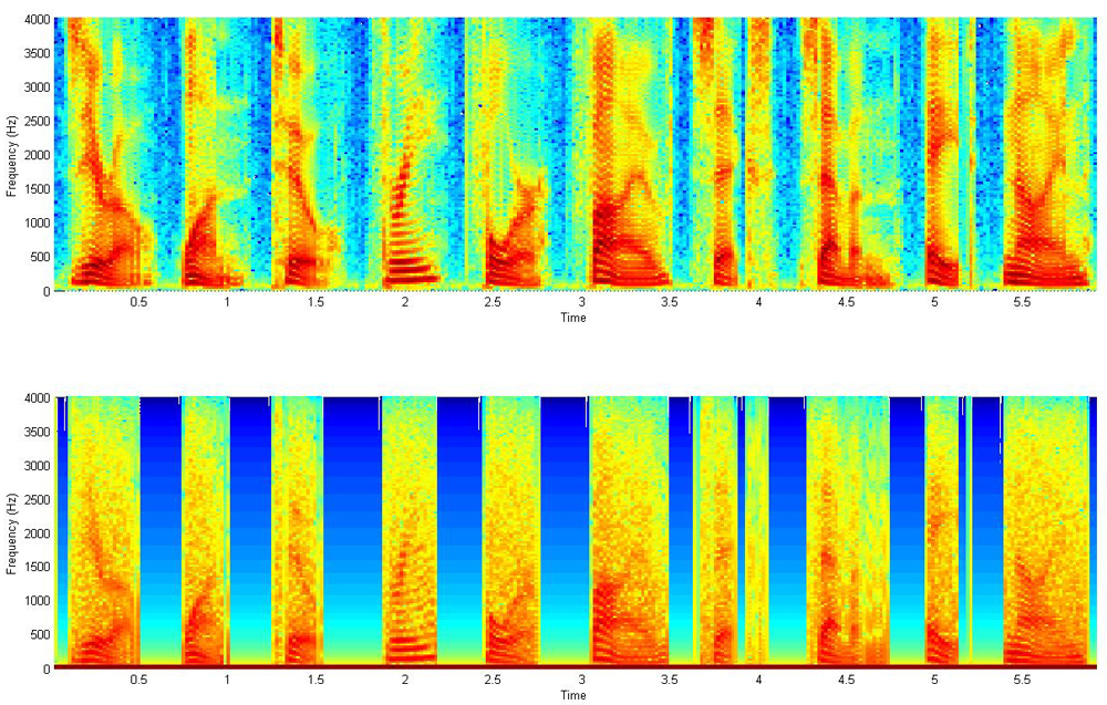
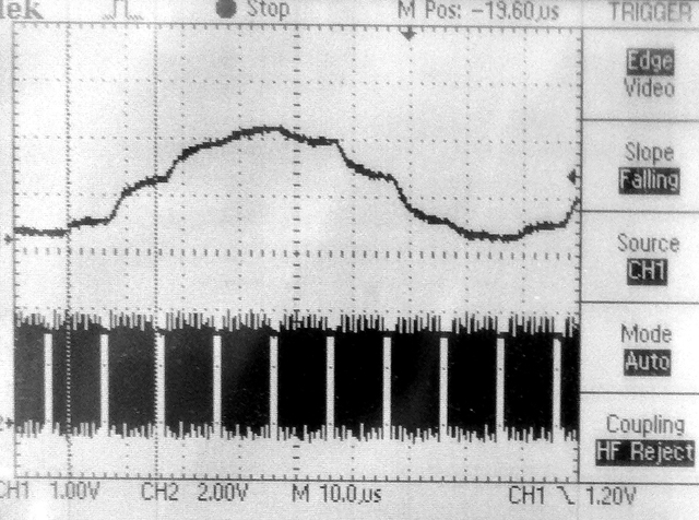
-- As shown in the section below, the Vref generator can be used as a DAC (pin 25 on PIC32MX250F128B). While 4-bits of dynamic range is not going to hack it for playing back Grateful Dead albums, it is good enough for a quick sound effect or medium quality voice production. There are several steps. First get a low dynamic range WAV file. I use the AT&T text-to-voice site to produce a WAV file with a male voice saying the digits zero to nine. Then the WAV file is processed with a Matlab program to adjust the sample rate, truncate the PCM values to 4-bits, then pack two four bit samples into each byte for storage efficiency. Next the Matlab program produces a header file of the packed samples formated so that it is loaded into flash memory. Then the playback program running on the PIC32 traverses the packed array at 16 KHz and drops the unpacked samples onto the Vref DAC. The low sample rate means that the male voices at the AT&T site sound better because we can more heavily filter and not lose too much voice content. The following image used matlab's spectrogram utility to compare the original and 4-bit quantized sounds. The top image is the 8 KHz sampled voice. The bottom image uses the signal quantized to 16 levels, then lowpass filtered with a RC filter with a cutoff of 1700 Hz. Each digit (0 to 9) is visible and the overall structure is the same, but not as crisp. The actual playback circuit used an RC filter consisitng of a 100k resistor and 1nf capacitor to get the lowpass. The quantized, filtered matlab output sounds very much like the PIC output.
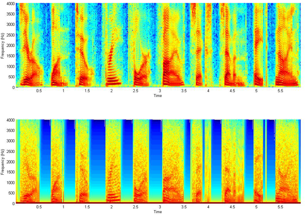
-- The 4-bit data is highly redundant. Looking at the difference between sequential samples shows that over 98% of the transitions between sequenctial samples are plus/minus one or zero. This means that if we encode the difference as a two bit number, we can make a smaller header file without losing too much information. The matlab encoder takes the differences, truncates them, resynthesises the wave from the truncated derivitive and plays the digits. Still to be done: Pack the four 2-bit difference samples into one byte and write the header file and decoder in C. The following images show the spectrogram of the raw speech after sampling to 8 kHz and the spectrogram of the waveform reconstructed from 2-bit differences.
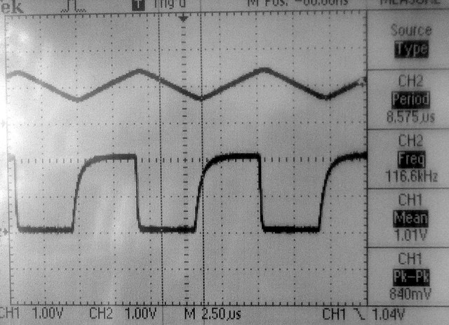
-- The Vref generator can be connected to an external pin (pin 25 on PIC32MX250F128B) and can be set to 16 values between zero and two volts. The first example generates a 16-sample square wave to investigate the settling time of the DAC. According to the Reference Manual, the output impedance at output level 0 (about zero volts) is about 500 ohms, while the output impedance at output level 15 (about 2 volts) is around 10k ohms. The first screen dump shows the Vref voltage output on the bottom trace and the same signal passed through an LM358 opamp, set up as a unity gain impedance buffer, on the top trace. Rise time (level 15) is about 0.5 microSec (to 63%) and fall time (level 0) is about 0.05 microSec. The rise/fall times are dominated by the RC circuit formed by the output impedance of Vref and the capacitance of the white board (10-20 pf) and the scope (20 pf). The LM358 is slew-rate limited and thus produces a triangle wave.
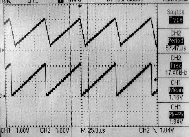
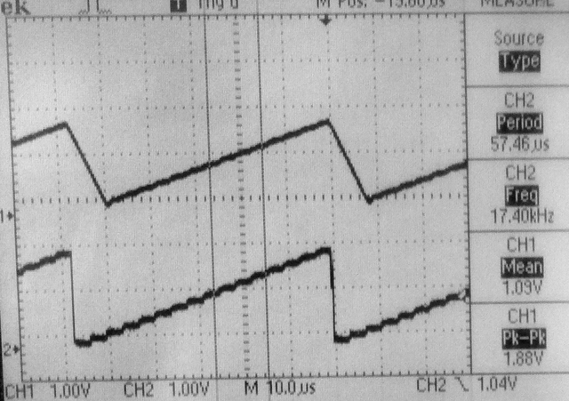
-- The next example generates a sawtooth with a period of 128 phase increments (17.4 kHz). The bottom trace is taken directly from the Vref pin, while the top trace is from the output of the unity gain LM258 follower. Notice the slew-rate limiting on the falling edge of the sawtooth.To unload the Vref pin, the output was connected to the opamp follower through a 100k resistor. A lowpass filter using the 100k resistor and a 10 pf capacitor with a time constant of around 1 microSec smooths and denoises the opamp trace (third image).
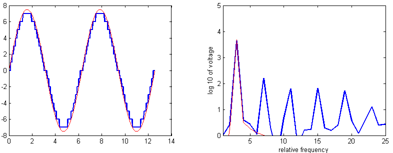
-- Any real application is going to use ISR-driven timing to output samples to the DAC. The next example uses Direct Digital Synthesis (DDS) running in an ISR at 100 kHz to generate sine waves. Tiiming the ISR using a toggled bit in MAIN, suggests that the 47 assembler instruction ISR executes (with overhead) in 1.5 microSeconds. The first image shows the DDS sine wave (but at very high frequency) on the top trace and the bit being toggled in MAIN on the bottem trace. You can clearly see the 1.5 microsecond pause in MAIN every time a new sine wave value is produced. The second image is a sine generated at Middle C (261.6 Hz). The top trace in the lowpassed opamp output. The bottom is the raw Vref pin.The code is structured as a timer ISR running the DDS. The output frequency is settable within a millHertz, but accuracy is determined by the cpu clock. Sixteen voltage levels introduces some harmonic distortion. The first error harmonic is about a factor of 30 in amplitude below the fundamental and at 3 times the frequency. This is in line with Bennett for 4-bit signals. The matlab image shows the full and 16-level sampled sine waves on the left and their spectra on the right (code). Listening to the signal gives a sense of very high frequency spikes. Lowpass filtering with a time constant equal to about 1/(sample-rate) gets rid of most of the sampling noise..
-- The XC32 compiler libraries treat UART2 as standard-in and standard-out. Using the examples from (ref 1) and from
C:\Program Files (x86)\Microchip\xc32\v1.31\examples\plib_examplesI wrote a minimal UART interface example which can get individual characters, get strings, and use
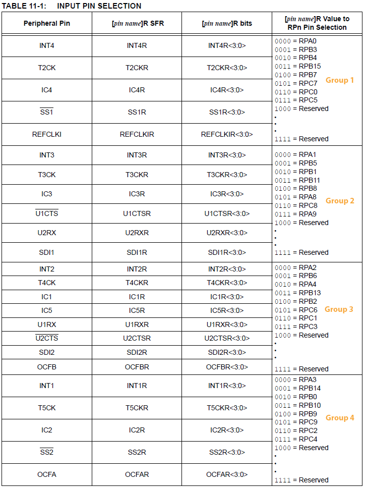
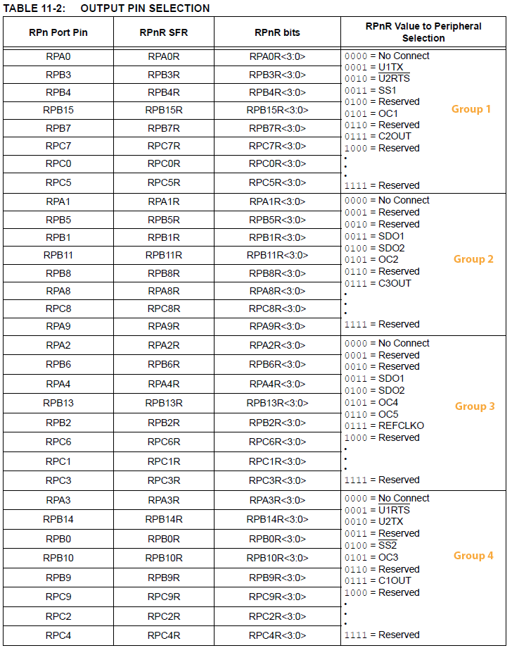
printf. I could not make scanf work, but getting a string and using sscanf is a workaround. The UART input/output is not routed by default. You must specify a peripherial pin select (PPS) option as described in http://people.ece.cornell.edu/land/courses/ece4760/PIC32/Microchip_stuff/2xx_datasheet.pdf
Table 11-1 which gives input pin mapping, and Table 11.2 which gives output pin mapping. The minimal setup seems to be:
    // specify PPS group, signal, logical pin name
    PPSInput (2, U2RX, RPB11); //Assign U2RX to pin RPB11 -- Physical pin 22 on 28 PDIP
    PPSOutput(4, RPB10, U2TX); //Assign U2TX to pin RPB10 -- Physical pin 21 on 28 PDIP
    // init the uart2
    UARTConfigure(UART2, UART_ENABLE_PINS_TX_RX_ONLY);
    UARTSetLineControl(UART2, UART_DATA_SIZE_8_BITS | UART_PARITY_NONE | UART_STOP_BITS_1);
    UARTSetDataRate(UART2, PB_FREQ, BAUDRATE);
    UARTEnable(UART2, UART_ENABLE_FLAGS(UART_PERIPHERAL | UART_RX | UART_TX));
-- All the setup functions are documented in the MPLAB-X help files under XC32-peripherial libraries. There is one helper function in the example, GetDataBuffer(), which buffers the input from the UART and echos the input, until an <enter> keystroke occurs, then zero-terminates the string and emits a CRLF to position the cursor on the next line. Notice that the function is blocking because it waits, possibly forever, in the while(!UARTReceivedDataIsAvailable(UART2)){}; for the user to type. -- The
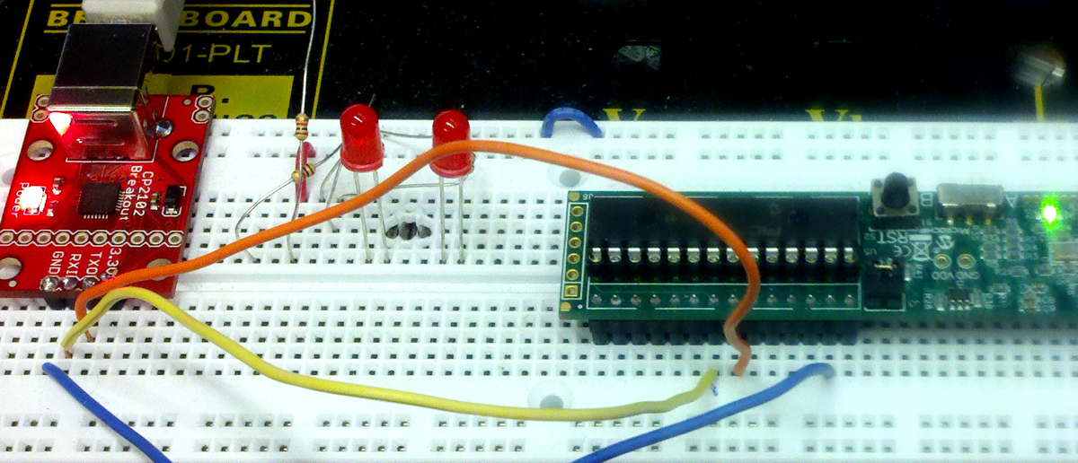
GetDataBuffer() function above is a little annoying because you cannot backspace over a mistake. Adding a backspace is easy (code) but you have to make sure that your terminal uses control-H (ascii code 0x08) as the backspace code. In PuTTY you have to right-click the title bar, choose Change Settings..., then choose the Terminal-Keyboard panel and choose the control-H backspace.-- The physical interface to the PC was a Sparkfun CP2102 USB-UART interface with the
CP2102 TX pin hooked to MCU pin 22 (U2RX), the CP2102 RX pin hooked to MCU pin 21 (U2TX),
and of course, the CP2102 ground pin hooked to MCU pin 27 (or pin 8, see ref 8-2).
PIC32 supports direct memory access from/to peripherials, flash memory and RAM. Code is based on examples from
C:\Program Files (x86)\Microchip\xc32\v1.31\examples\plib_examples\dma-- The first image below shows a DMA burst on the top trace and a separate port pin being toggled in
main on the bottom trace. The DMA burst is triggered by a timer interrupt, but the interrupt does not trigger an ISR, just the DMA. Individual transfers within the burst are not uniform in time and range from 10 MHz to 5.5 MHz. The code sets up the DMA to burst 16 entries from a table (in flash or RAM) to an i/o port once every 2.5 microseconds. If the burst length is set to one (one byte at a time) triggered by a timer, the fastest I could get the system to go is 3.7 MHz (270 nSec per transfer). -- The second image shows two DMA channels (code) activated by the same timer IRQ every 5 microSec. Both DMA channels have the same DMA priority and both are sending 16 bytes to an i/o port. The DMA controller seems to interleave 4-byte bursts from each DMA channel. Each byte within each 4-byte burst takes 100 nSec. The latency between one channel and the other is about 72-120 nSec (~3-4 cycles).
-- The third image shows two DMA channels (code) activated by the same timer IRQ every 5 microSec. The DMA channels have the different DMA priorities and both are sending 16 bytes to an i/o port. The high priority channel sends, then the low priority channel. There is a 4 or 5 cycle latency between the bursts.
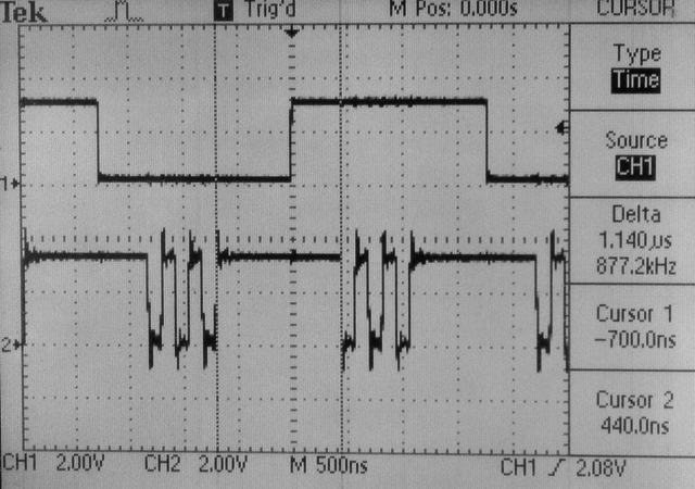
It is useful to know the minimum number of cycles to service an intrrupt. Overhead can include saving the state of the machine, reseting flags and restoring the state of the machine. Of course, you need to add in the actual processing you are doing in the ISR. A minimal timer ISR just toggles an i/o pin and returns. The compiler generates about 33 instructions to do this minimal ISR, but this number does not include hardware overhead. Actual execution suggests that the interrupt takes a little less than 50 cycles total for this minimal ISR (Three cycles are the actual pin toggle). This works out to be 156 kHz interrupt rate at the default 8 MHz system oscillator frequency and 780 kHz interrupt rate at 40 MHz system clock. This code has the clock set to 40 MHz, explicitly sets the peripheral bus divider to one, and documents the sections of the manual explaining the timer interface.
Adding a bit-toggle in main results in the following image. The top trace is the ISR toggle, the bottom trace is the toggle in main. You can see that main stops executing about 700 nSec (about 28 cycles at 40 MHz) before the ISR toggle executes, then starts again about 450 nSec (about 18 cycles at 40 MHz) after the edge on the ISR trace. This gives some idea of how long it takes to get into and out of an ISR, but is only approximate (I would say +/- 6 cycles). The loop in main is running at 8.0 MHz per toggle (five instructions). Turning up the clock to 72 MHz (remember that the chip is rated at 40 MHz) gives a maximum interrupt frequency of 1414 KHz. Timer2 fails at a clock frequency of 76 MHz. Chip is warm to the touch at 72 MHz.
This code is derived from Chapter 8 of Kibalo's book (see below) and modified to run at 40 MHz. Main was modified to loop and toggle an i/o pin as fast as possible at 5.71 MHz Using direct LATA access. This implies that the number of instructions in the main loop is 7 cycles long. Using the menu
Window>Output>Disassembly Listing shows the assembler code generated.
45:            while (1) {
46:                  LATA =0x0001;          // set latch levels for PORTA
9D00021C  3C02BF88   LUI V0, -16504         // Load upper immediate
9D000220  24030001   ADDIU V1, ZERO, 1      // Integer unsigned add immediate
9D000224  AC436030   SW V1, 24624(V0)       //Store Word Mem[Rs+offset] <= Rt
48:                  LATA =0x0000;		  // set latch levels for PORTA
9D000228  3C02BF88   LUI V0, -16504        // Load upper immediate
9D00022C  AC406030   SW ZERO, 24624(V0)    // Store Word Mem[Rs+offset] <= Rt
50:             }
9D000230  0B400087   J 0x9D00021C          // jump back to 9D00021C
9D000234  00000000   NOP
Three instructions load the i/o address of the port and a one, then output the one to the address, two instructions clear the port pin by loading a zero, and two cycles are taken to jump back. The waveform stays high for two cycles (50 nSec, the time to clear the pin) as shown below.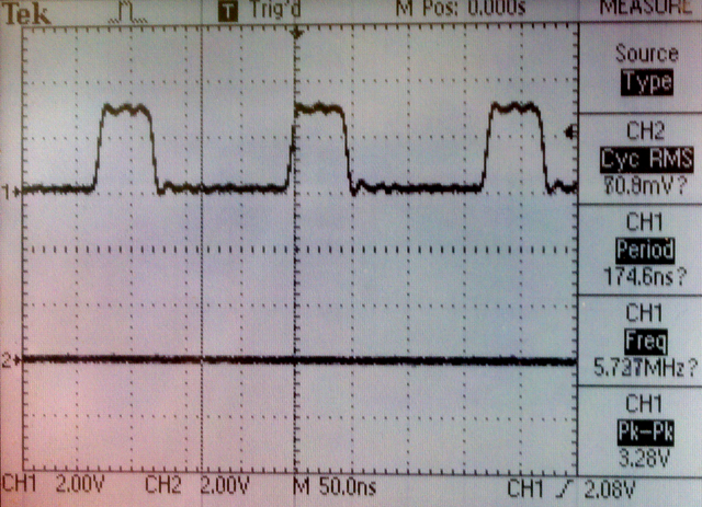
Using the ligher level commands
mPORTASetBits(BIT_0);

    mPORTAClearBits(BIT_0);
in the loop instead of setting LATA directly increases the cycle count by one and drops the frequency to 5 MHz, but is prefered style.
The assembly code shows that set/clear are each three cycles. This implies that the time the pulse is high is 75 nSec.
Changing two lines in the code
#pragma config FPLLMUL = MUL_18        // PLL Multiplier (18x Multiplier)

    #pragma config FPLLODIV = DIV_1         // System PLL Output Clock Divider (PLL Divide by 1)
will run the cpu at 72 MHz but that is out of specification. It may burn or peripherials may not work. Setting
FPLLMUL = MUL_19 runsthe cpu at its maximum frequency of 76 MHz. Setting the multilpiler to 20 fails.