Cornell University ECE4760
Direct Memory Access weird machine
PIC32MX250F128B
Bruce Land and Joseph Primmer
DMA on PIC32
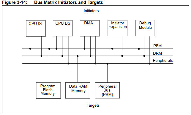
DMA uses memory controllers separate from the CPU to accelerate data movment between memory locations, or between peripherials and memory. The PIC32 has 4 DMA controllers which can stream an agregate of about 3.2 megabytes/sec without affecting CPU performance, in many cases. There are a huge number of options available to set up a DMA transfer. You can think of a DMA channel controller as a separate, programmable, processor with the main job of moving data. Memory on the PIC32MX series is arranged as a bus matrix with five memory bus control masters and three memory bus targets accessed by the masters see (Refence Manual chapter 3, section 3.5).
Here we use the DMA subsystem to produce a complete computing system, independent of the main PIC32 CPU. The DMA weird machine makes use of memory-copy ability, transport_triggered operations, and self-modifying code. The code consists of a sequence of DMA block descriptors. The implemented operations are Turing Complete, but probably too slow for general computing. About 200,000 DMA blocks/second can be fetched/executed. The operations may be useful as glue-logic to link together peripherials. For instance, the existing PIC32 hardware allows you to trigger an ADC conversion from timer3, but not timers 1, 2, 4, or 5. Using DMA sequential machine you could trigger from any timer, then send the sample by SPI, using zero CPU cycles.
Fetch/execute DMA weird-machine functions:
All functionality must be based on memory copy operations. (see also x86 mov is Turing-Complete) The way to use memory copies to make more general operations is to execute a sequence of memory copies, where some of the copy operations modify the contents of the DMA control blocks for operations later in the sequence. The basic fetch/execute machine uses DMA0 to load a sequence of DMA2 block images, each of which is initially defined in a large array. By carefully modifying DMA2 control block images in the array, just before they are transfered to the hardware DMA2 control block, we can perform addition, increments, conditional jumps, and/or/not logic operations, and any other operations required. Program branching is implemented by using DMA2 to load a new DMA0 block. There are program labels coresponding to the index of the next block in the array. The labels are necessary for general branch support. When modifying addresses for DMA blocks, some care is necessary because on the PIC32 all C variable addresses refer to virtual memory addresses, but the DMA system works in physical address space. The PLIB DMA constructors do the conversion for you, but when hacking addresses directly you need to do the conversion yourself. The implemented operations are Turing Complete, with the limitation of a maximum of ~100 DMA blocks available, one byte variables and modulo 256 addition.
In addition to a straight copy operation, there are a few transport-triggered operations in the PIC32 DMA system:
- Writing to certain shadow registers associated with each special function register (SFR) clears, sets, or inverts bits in the SFR.
This allows universal logic operations in each SFR as a result to transfering data to the register.
Every peripherial control register (ports, timers, DMA, everything) is an SFR with three shadow registers!
- For two logic bits A and B:
- load B then SET bits using A as a mask implements OR
- load B then CLR bits using NOT(A) as a mask implements AND
- load B then INVERT bits using A as a mask implements XOR
- The DMA system itself supports computing a CRC on-the-fly while transfering data.
There is an in-line LFSR which can be configured to modify data.
An example below uses this to generate white noise on the DAC.
- Any DMA channel transfer can be terminated on detection of a 1-byte data-match during transmission.
This could be used for a compare operation, perhaps.
- Of course, writing certain SFRs may have system functions.
For instance, writing to an i/o port sets the value of output pins.
Or setting an interrupt flag will force a cpu interrupt.
The DMA test program performs several operations using only DMA-logic. the DMA machine is completely asynchronous and independent of MAIN, once started. MAIN sets up the DMA machine program, defines tables for the machine, then prints the results of an ADD and NOR operation on the serial console. No other microcontroller resources are needed (except memory, of course) to make the machine run. The execution speed is about 200,000 blocks/sec.
The DMA weird-machine program:
- Sends a trigger pulse to PortA, for an oscilloscope
One DMA2 block to transfer one byte to LATA.
- Increments a variable to be used in the arithmetic below
Two DMA2 blocks:
--
move variable value to low byte of source address field (increment array) of next DMA block.
-- move value in source address
to variable. Contents of increment array is (source addr low-byte value)+1.
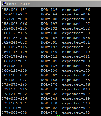
- Adds two 8-bit variables and stores the result (terminal image showing sum, modulo 256, and result of NOR operation below)
Four DMA2 blocks:
-- move variable_1 value to low byte of source address field (increment array) of DMA block 3 blocks later.
-- move variable_2 value to low byte of source length field (increment array) of DMA block 2 blocks later.
--
move variable_2 value to low byte of cell length field (increment array) of DMA block 1 block later.
-- increment through the table specified by the previous three blocks and store result into variable_4.
- Computes the NOR of the two 8-bit variables and stores the result
These operations use transport-triggered operations built into SFR to implement logic.
Four DMA2 blocks:
-- move variable1 value to an SFR that supports (CLEAR, SET, INVERT) write locations.
-- move variable2 value to the SFR SET write location.
-- move 0xff value to the SFR INVERT write location.
-- move NOR value in the SFR to variable_3
- Sets a print strobe, to be cleared by MAIN when the variables are printed.
This is necessary because the DMA machine is completely asynchronous with the CPU
-- One DMA2 block to move a 0x01 to the print strobe, which is cleared by the CPU in MAIN.
- Computes a conditional branch to see if the print strobe is cleared, and loop until it is cleared.
Five DMA blocks to compute branch:
--
move print_strobe to low byte of source address field (offset array) of next DMA block.
This effectively multiplies the logical 0/1 to 0/4 because the jump address is 4 bytes
-- move the offset to
low byte of source address field (jump array) of next DMA block.
This will select the jump address entry from the jump table.
--
move the actual target block address to
low two byte of source address field of the DMA0 block two blocks ahead.
-- move the next block to DMA0 control registers.
-- define
the DMA0 block to be moved by the previous block.
- Increments a variable, modulo 3, to choose one of three output wavefroms to send to PortB
- Computes a conditional branch to one of three waveform generators based on the mod 3 variable:
-- 1 microsec pulse
-- 2 microsec pulse
-- 8 microsec pulse
- Unconditional jump back to the beginning of the program (item 1 on this list)
Fetch/execute machine details:
The syntax given below assumes that DMA0 or DMA2 block images can be built by defining them using PLIB DMA commands, then copying the blocks (in the perparation stage) to the large array or arrays of block images. Macros hide the actual preparation and abstract the preparation to specifying the source address, destination address, source length (in bytes), destination length (in bytes), and the cell transfer length (in bytes). For example:
make_DMA2_block(LED_pattern2, (void*)&LATB, 64, 1, 64);
constructs and stores a block destined to be copied to the DMA2 control block which moves 64 bytes from a memory array, in a burst of 64, to the 1 byte
port B output latch. The effect is to generate a burst of output transitions on the port, when the block is later loaded into the DMA2 control register and executed.
- Output to a port:
There at least two ways to make a pulse on an output pin. One way was described above of moving an array to a port.
The other way is to use the PIC32 special-function-register shadow registers explained in a separate bullet below:
make_DMA2_block(&test_var_0, (void*)&PORTB, 1, 1, 1); // test_var_0 = 0x01
make_DMA2_block(&inv_mask, (void*)&PORTBINV, 1, 1, 1); // inv_mask = 0xff
The first block turns on port B, bit zero. The second block inverts the entire latch byte to turn off bit zero.
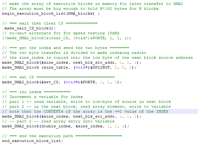
- Increment a variable:
Increment uses the value of a variable as an index into an array which has contents equal to index+1. For this to work you have to be able to copy the variable into the low byte of the source address of the next block. You also have to align the array in memory so that the base address of the array has a zero-valued low order byte. Perparation includes the array definition, which in this case causes the byte-aligned variable to cycle through three values. The macro next_blk_src_addr calculated to memory address of the source field of the next defined block.
unsigned char jmp_inc_array[] __attribute__ ((aligned(256))) = {1, 2, 0} ;
make_DMA2_block(&inc_value, next_blk_src_addr, 1, 1, 1);//load to low-byte of source address in next block
make_DMA2_block(jmp_inc_array, &inc_value, 1, 1, 1); // read array entry back into variable
- Logic operations:
Special function registers (e.g. DMA control blocks, or i/o ports), which are writable all have three shadow, write-only, registers. The shadow registers are write-only addresses and act as bit-mask modifiers of the main register. The three registers allow you to set, clear, or invert individual bits in the main register. As an example, writing 0x04 to PORTBINV negates the third bit of PORTB. The general naming scheme is sfrSET, sfrCLR and sfrINV. I chose to use sfr that are normally used to set compare data for DMA transfer termination. The actual termination function is not turned on, so these registers are not used by the weird machine. For example, to compute the bit-wise NOR:
make_DMA2_block(&test_var_1, scratch_sfr, 1, 1, 1); //scratch_sfr load
make_DMA2_block(&test_var_2, scratch_sfr_set, 1, 1, 1); // OR in another variable
make_DMA2_block(&inv_mask, scratch_sfr_inv, 1, 1, 1); // invert to make NOR operation
make_DMA2_block(scratch_sfr, &test_var_3, 1, 1, 1); // store to third variable
- Add two variables:
To add two variables you need to supply three pieces of information to one block for one table lookup. The table lookup uses the fact that moving a series of bytes is exactly the counting operation which is necessary to add. Variable test_var_1 is used as the offset into an array to start the count. Variiable test_var_2 is used as both the size of the source, and the number of bytes to move, but all of the bytes move to one target byte, essentially making a counter. There an edge condition when test_var_2=0, which means that the size of the transfer has to be at least 256 bytes, hence the 0x100 size in the last block. As usual, the actual value of a table-lookup is substituted into the low-order byte of the next block's source field, or size field. Note that the inc_array is 768 byte long (256x3) to account of the zero edge case and longest possible increment sequence.
// --load first operand into blocK+3 source addr
make_DMA2_block(&test_var_1, (void*)(DMA_blocks+length_of_block*(N+3)+DCH0SSA_OFFSET), 1, 1, 1);
// -- load second operand into block+2 source SIZE !!!!CANNOT BE ZERO!!!
// Hence the 0x100 offset two blocks down
make_DMA2_block(&test_var_2, (void*)(DMA_blocks+length_of_block*(N+2)+DCH0SSIZ_OFFSET), 1, 1, 1);
// -- load second operand into block+1 cell SIZE !!!!CANNOT BE ZERO!!!
// Hence the 0x100 offset in the next block
make_DMA2_block(&test_var_2, (void*)(DMA_blocks+length_of_block*(N+1)+DCH0CSIZ_OFFSET), 1, 1, 1);
// --read sum array entry into variable
make_DMA2_block(inc_array, &test_var_4, 0x100, 1, 0x100);
- Conditional jump:
Since every operation is a memory transfer, each branch of a computed jump must jump, so that the operations are uniform. There are several steps required.
- Assuming that the branch depends on the value of a byte variable, the branch scheme needs a lookup table in which each entry is the 4*(byte value).
example of a modulo 3 multiply table:
unsigned char offset_array[] __attribute__ ((aligned(256))) = {0, 4, 8} ;
The multiply table will be used to generate an 4-byte offset for each possible increment value.
The table
must be aligned in memory so that the lowest byte of the address is zero.
- The branch scheme also needs a lookup table in which each entry is the actual memory address of the next block to execute,
depending on the index, which is the value of the incremented variable
The address will be moved into the new DMA0 block.
example of
jump table: unsigned int jmp_array[3] __attribute__ ((aligned(256))) ;
later in the code, set
io_jmp_array[0] = DMA_blocks + one_short_pulse_label*length_of_block ;
io_jmp_array[1] = DMA_blocks + two_short_pulse_label*length_of_block ;
io_jmp_array[2] = DMA_blocks + one_long_pulse_label*length_of_block ;
But NOTE that these are virtual addresses which need to be converted to physical addresses.
The conversion is done by only using the lower two bytes of the array value.
- DMA block N copies the 1-byte increment variable into the low byte of the source address field of block N+1,
which contains the base address of the offset array.
- DMA block N+1 copies the modified offset array address contents into the low byte of the source address field of block N+2,
which contains the base address of the jump array.
- DMA block N+2 copies the modified jump array address contents into the low 2 bytes of the source address field of block N+4,
- DMA block N+3 copies block N+4 into the DMA0 control registers
- DMA block N+4 is the block (with new source pointer) to actually copy into the DMA0 control registers,
thus implementing a jump by updating the source pointer to the DMA block list in memory.
make_DMA2_block(&inc_value, next_blk_src_addr, 1, 1, 1);
make_DMA2_block(jmp_offset_array, next_blk_src_addr, 1, 1, 1);
make_DMA2_block(io_jmp_array, (next_blk_src_addr+length_of_block), 2, 2, 2);
make_DMA2_block(next_blk_addr, DMA0_addr_2, length_of_block, length_of_block, length_of_block);
make_DMA0_block(DMA_blocks, DMA2_addr_2, number_of_blocks*length_of_block, length_of_block, length_of_block);
- Unconditional jump:
An unconditional jump requires two blocks. This first block moves the second block to DMA0 control registers.
The DMA0_addr is the loacation of the DMA0 control registers, DMA_blocks the the address of the jump target.
The second block is to be moved to DMA0 to force jump to beginning of pgm and start loading blocks into DMA2
make_DMA2_block(next_blk_addr, DMA0_addr, length_of_block, length_of_block, length_of_block);
make_DMA0_block(DMA_blocks, DMA2_addr, number_of_blocks*length_of_block, length_of_block, length_of_block);
Direct Digital Synthesis -- A possible practical use for the DMA machine (and optimizing execution)
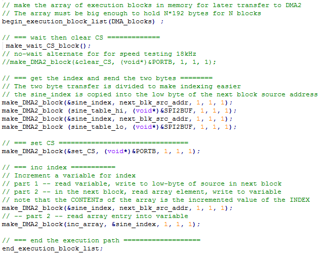
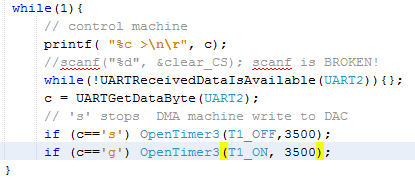
DDS uses a table-lookup to send sine values to a SPI-attached DAC. It is possible to do DMA transfer to the SPI using framed mode, which autogenerates a chip select on the channel slave-select line. However, the chip select is limited to one pin and there can only be one peripherial on the channel. The serial DMA machine allows you to define an arbitrary chip select pin and manipulate it. The downside is that the maximum speed for the transfer is around 11.4 Ksamples/sec (when using the standard 192 byte full DMA block definition). The example code waits for a timer event, toggles the chip select, sends two bytes through SPI to the DAC, increments an array pointer, then auto-loops back to wait the beginning for a timer event. To turn off the machine, just freeze timer3 so that another SPI device can access the bus. The demo code does this with a serial command.
--
The rate-limiting step in the DMA weird machine execution is loading the 192 byte blocks for every operation. Careful consideration of the contents of the DMA control block suggests that the last two words are not needed for this machine (unless you try to use transport-triggered compare). This shaves 32 bytes off. Another 12 bytes can be pulled off the end because each control register has three shadow registers for transport-triggered logic operations. The first word of the block is constant and can be set once, saving 16 bytes. The net result is 132 byte transfers which speeds up execution by about 1.5 times. The sample rate jumps to 18 Ksamples/second. Code.
-- Just running the DAC transfer as fast as possible with NO time-trigger control speeds up the sample rate to 23 Ksamples/sec. The speed up happens because the block size is cut to 100 bytes (minimum). The minimum size does not include the ability to set up a time trigger using the DMA block interrupt detect hardware. Code.
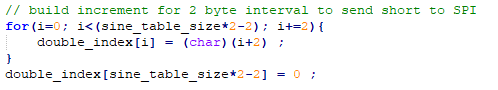
-- Changing the code to use 2-byte transfers to the SPI channel requires a modified increment table which limits the maximum sine resolution to 128 samples/cycle. The scheme makes a table in which the increment is two, rather than one. The effect is to remove two blocks from the DMA-block DDS loop, and raising the maximum synthesis frequency to 23.6 KHz (still with timer control). For the DDS sinewave this gives a frequency range from 2.95 Hz for a 8-sample sine to 184 Hz for a 128-sample sine. The 23.6 KHz synthesis rate corresponds to a timer interval of 1700 cycles. This means that changing the sample rate allows frequency control of better than 0.1%. Changing the length of the sine table by one sample yields frequency control of 1/(sine_table_size).
Code. <<use this version for DDS>>
Pseudorandom or random sequence generation
This example uses the CRC hardware module to generate a pseudorandom 16-bit
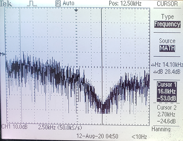
number sequence. OPtionally, reading a floating ADC input adds some entropy to make the sequence truly random, but not cryptograhic quality. The sequence is output through the SPI DAC interface for spectral analysis. If the ADC is used, it is read every eighth interation of the LFSR, with 8-bits of the ADC reading XORed with the lower 8-bits of the LFSR seed. Running the CRC LFSR, emitting the SPI data, computing the conditional ADC read all runs at about 10KHz. The code needs a 16-bit SFR to use as a 16-bit ALU. The OCR5 set/reset registers were used. This version of the code optimizes for speed by eliminating possible timer control, so the system just runs as fast as it can. Eliminating SPI output would speed up random number genration about 30%. Eliminating the ADC read would speed it up by about 25%, but makes the sequence completely repeatable, and dependent on the initial seed chosen. The output noise spectrum drops with a 3db point at about 25% of the sample frequency and a minimum at the sample frequency at least 30db down.
Code (with ADC read every three LFSR operations)
Spectrum of DAC output with no ADC reads. Sample rate is about 16.8 KHz.
Older versions:
Time synced operation:
It is possible to sync overall machine operation to a timer by modifying one DMA2 block definition to trigger a transfer on a timer event. Note that this is a blocking-wait, which kills DMA execution until the timer event. The could be useful for a small program that, for example, sends a word to the SPI channel on a regular schedule to run a DAC. The sequential machine would wait for a timer event, drop the chip-select line, transfer a word to the SPI buffer, raise the chip-select line, then loop to wait for the next timer event. The DMA2 block definition which waits, then executes a NOP could be:
DmaChnOpen(2, 0, DMA_OPEN_AUTO);
DmaChnSetTxfer(2, &inc_value, &bit_bucket, 1, 1, 1);
DmaChnSetEventControl(2, DMA_EV_START_IRQ(_TIMER_3_IRQ));
DmaChnSetEvEnableFlags(2, DMA_EV_CELL_DONE);
DmaChnEnable(2);
memcpy(DMA_blocks+length_of_block*N, &DCH2CON, length_of_block);
N++;
This
code runs the main DMA loop at 100 Hz by waiting for timer3 event.
Optimizing test code execution speed
-- The execution speed of the DMA machine is limited by the need to load a 192 byte control block for each operation. By reducing the felxibility of the machine, certain chunks of the DMA2 block do not need to be reloaded each time. An optimized version with about 1.4 speed-up minimizes DMA2 block updates, but still allows full functions described above. optimized code.
The minimum execution time for one block dropped from 10 µsec to 7 µsec because the bytes per block were reduced from 192 to 132.
--
It is possible to optimize further, but the ability to trigger a block from an outside source (perhaps a timer) is lost. By eliminating the copy of the interrupt control registers, the copy count drops to 100 bytes, and the minimum block execution time drops to 5.5 µsec. The general test code above still runs, but time sync is much harder. The DCHxSSA, source address, register is the first address copied and the DCHxCSIZ, cell size register, is the last (see datasheet page 52).
A different (and probably inferior) way to run the Fetch/Execute cycle
The method used above is optimal in terms of wasting no cycles because the fetch/execute cycle is asychronous. As soon as an operation finishes, then next one can start. However, all four DMA channels are needed to make the machine run. One channel is the fetch unit, another is the execute unit, and two others are just used to clear interrupt flags in the first two channels.
If a timer and output compare unit are used to generate two time-synched interrupt flags, then the two (fetch and execute) DMA channels can be triggered by the interrupt flags. The up side of this scheme is that it frees up two DMA channels. The down side is that the slowest operation determines the execution rate of the machine. Most operations are fairly fast, but add is much slower and branch is a little slower. Including add operation drops performance by a factor of 10. Branch operation drops performance by a factor of 2.5. Tuning becomes quite dificult. But for reference, a running code (without add operation) is included which runs about 0.4 as fast as the async code. Code.
Copyright Cornell University
March 27, 2021