Cornell University ECE4760
Adafruit TFT LCD Display Model 1480
PIC32MX250F128B
Adafruit Color LCD Model 1480
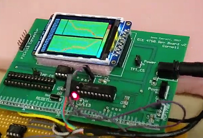
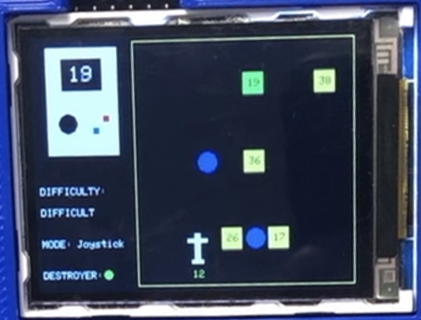
The display we are using is a 320x240 color LCD with 16-bit color specification. Communication is by SPI (and a couple of extra control lines) from the PIC32 using a graphics library ported to PIC32 by Syed Tahmid Mahbub, as explained on his excellent blog. The display is directly supported by the SECABB development board. Below are two student project examples of displays using the LCD.
Graphics Details
The display location x=0, y=0 is in the upper-left corner of the screen.
In landscape mode (rotation mode 1), the maximum x=319, maximum y=239.
In portrait mode (rotation mode 0, the default), the maximum x=239, maximum y=319.
The Adafruit TFT color format is 16 bit:
A list of the available graphics routines is below. Defined in tft_gfx.h with more explanation of parameters in tft_gfx.c.
The low-level SPI-to-display support is in tft_master.h and tft_master.c.
The actual display controller on the TFT board is a ILI9340.
| Graphics function | Effect |
| void tft_drawLine(short x0, short y0, short x1, short y1, unsigned short color); | Draws a line with end coordinates (x0,y0) and (x1,y1) with a specified color. |
| void tft_drawRect(short x, short y, short w, short h, unsigned short color); | Draw a rectangle outline with top left vertex (x,y), width w and height h and given color |
| void tft_drawCircle(short x0, short y0, short r, unsigned short color); | Draw a outline circle with center (x0,y0) and radius r, with given color |
| void tft_fillCircle(short x0, short y0, short r, unsigned short color); | Draw a filled circle with center (x0,y0) and radius r, with given color |
| void tft_drawTriangle(short x0, short y0, short x1, short y1, short x2, short y2, unsigned short color); | Draw a triangle outline with vertices (x0,y0),(x1,y1),(x2,y2) with given color |
| void tft_drawRoundRect(short x0, short y0, short w, short h, short radius, unsigned short color); | Draw a rounded rectangle outline with top left vertex (x0,y0), width w, height h and radius of curvature r at given color |
| void tft_fillRoundRect(short x0, short y0, short w, short h, short radius, unsigned short color); | Fill a rounded rectangle outline with top left vertex (x0,y0), width w, height h and radius of curvature r at given color |
| void tft_setCursor(short x, short y); | x = x-coordinate of top-left of text starting and y = y-coordinate of top-left of text starting |
| void tft_setTextColor2(unsigned short c, unsigned short b); | The 16-bit text color c and background color b |
| void tft_setTextSize(unsigned char s); | s = integer text size (1 being smallest) |
| void tft_writeString(char* str); | Print text onto screen. Call tft_setCursor(), tft_setTextColor(), tft_setTextSize() as necessary before calling this function |
| void tft_drawPixel(short x, short y, unsigned short color) | Low level routine to change one pixel. |
| void tft_drawFastVLine(short x, short y, short h, unsigned short color) | Draw a vertical line at location from (x,y) to (x,y+h-1) with specified color |
| void tft_drawFastHLine(short x, short y, short w, unsigned short color) | Draw a horizontal line at location from (x,y) to (x+w-1,y) with color |
| unsigned short tft_Color565(unsigned char r, unsigned char g, unsigned char b) | Pass 8-bit (each) R,G,B, get back 16-bit packed color for all other graphics functions |
| Initialization: | |
| void tft_gfx_setRotation(unsigned char r); | r=0 means vertical (portrait mode) r=1 means horizontal (landscape mode) |
| tft_init_hw(); | Call this first |
| tft_begin(); | Call this second |
| Additions by BRL4: see below for examples | |
| tft_printLine(int line_number, int char_indent, char* print_buffer, short text_color, short back_color, short size) | Print on a specified line from a print buffer with specified indent, color, background color, and size |
Drawing text
To make is easier to format debugging messages, I wrote a short single-line print routine:
void tft_printLine(int line_number, int char_indent, char* print_buffer, short text_color, short back_color, size)
that takes as input:
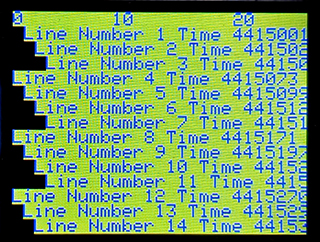
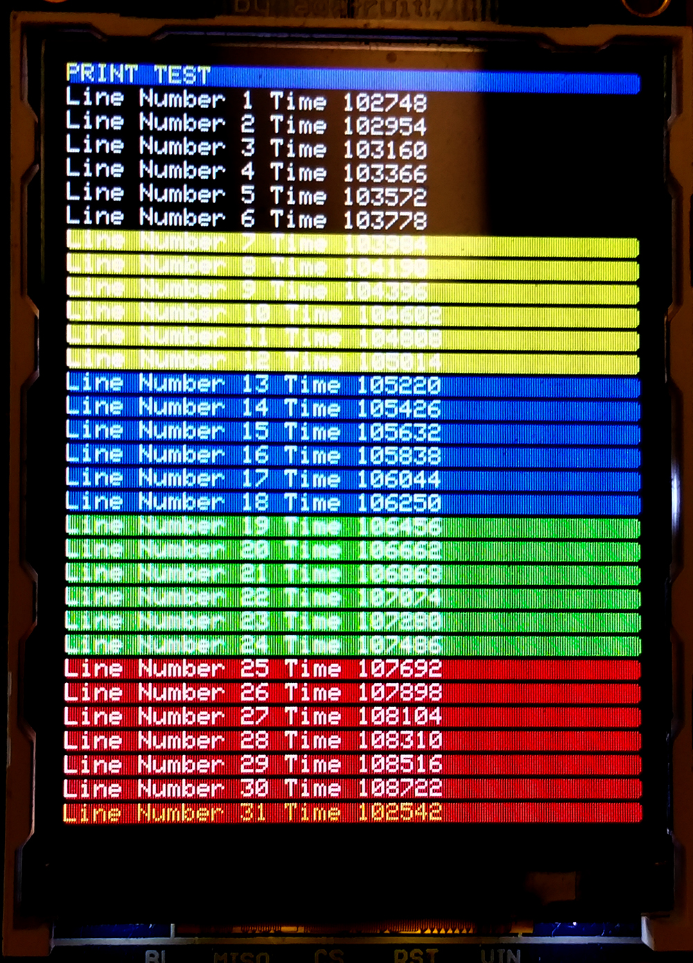
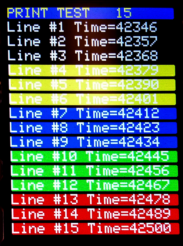
The demo code cycles slowly through four text sizes ,and serveral ugly color combinations, for each of two display rotations (portrait and landscape). The image below shows landscape mode (tft_rotation=1), with size=2 blue (ILI9340_BLUE) text on a yellow (ILI9340_YELLOW) background. The top line of the image is a line character counter. Each line is indented individually.
Bouncing ball animation example
Using the _Accum type s16.15 fixed point, we can build a numerical integrator to simulate a ball bouncing. The example code updates a timer and Euler-integrates F=ma separately for the x and y directiona, with gravity acting in the positive-y direction and with drag proportional to speed.
Euler integrators for veocity and position.
vyc = vyc + g - (vyc * drag) ;
vxc = vxc - (vxc * drag);
xc = xc + vxc;
yc = yc + vyc;
Diffusion example animation
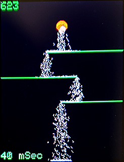
This random-walk diffusion example animates 1000 point particles, profiles the execution time, and maintains a elapsed time clock. The example uses an point drawing routine which takes about 10 microseconds/point to draw/erase. Most of that time is spent in SPI communication with the TFT display.Execution time for 1000 particles is about 20 milliseconds/frame, dominated by a draw and an erase for each particle. The code draws a particle source and three barriers. The particles fall because the randow walk is biased toward positive y velocity. When they reach the bottom of the screen, they are recycled to the source. This a crude simulation of water particles falling at terminal velocity with lots of turbulence.
Code, Image, video
Diffusion-limited aggregation
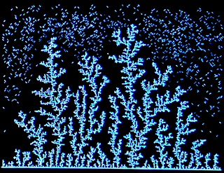
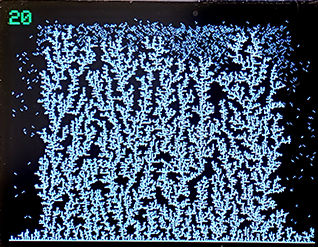
Diffusion-limited Aggregation (DLA) builds complicated structures from particles based on random diffusion of sticky particles. The particles stop moving whenever they touch part of an existing cluster of particles, so that the cluster grows through accumulation of particles. The example shown here starts with a cluster consisting of a line across the bottom of the screen to which diffusing particles can stick. Local depletion of particles results in branching, tree-like structures growing toward the top of the screen. The code performs about 50000 diffusion steps/sec, and with a diffusion bias of 130, takes about 126 seconds to generate a cluster of 15860 particles. The diffusion bias would be a fair 50/50 coin toss for up/down steps if the bias were set to 127. If the bias is increased to 150, so that the particles tend to fall, then the generation time for a screen filled with cluster is about 35 seconds for a cluster of 26000 particles. There is no mechanism (on our boards) to read back the TFT screen pixels, so a bit map copy of the screen is stored in memory. There are 70800 pixels on the TFT, so the bit map had to be packed to fit into the 32768 byte RAM of the PIC32MX250. Each char array address holds 8 bits, so the whole bit map fits into 9600 bytes. Two small look-up tables converted the x-coordinate into an array address, and a bit-offset within the byte. (Code) This process models Lichtenberg figures, metal dendrites, soot, ice crystals on glass, and many other natural systems. The first image below was generated with bias=130, the second with bias=150.
Diffusion with collisions and occupancy (fluid)
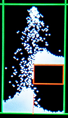
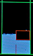
Adding the condition that a diffusing particle cannot move into a location which is already occupied causes a diffusive system to be space-filling. If there is a small downward bias in the diffusion, then you get fluid-like filling of low points. The flow has no conserved momentum, so the approach to equilibrium is somewhat non-physical. The simulation restricts the area of the screen used because memory (and animation rate) constrains the number of particles. There is a box-like barrier and a vertical line over which the fluild must flow.
There is no mechanism (on our boards) to read back the TFT screen pixels, so a bit map copy of the screen is stored in memory. There are 70800 pixels on the TFT, so the bit map had to be packed to fit into the 32768 byte RAM of the PIC32MX250. Each char array address holds 8 bits, so the whole bit map fits into 9600 bytes. Two small look-up tables converted the x-coordinate into an array address, and a bit-offset within the byte. The following images shows the system after a few frames with falling particles, then later near equlibirum. (Code)
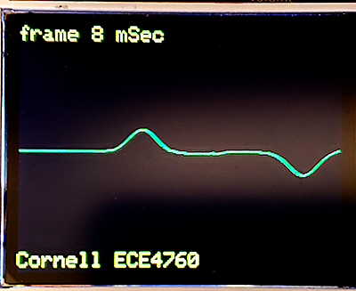
Wave equation animation
A more elaborate animation involves solving the wave equation on a 1-D medium (string). Solving the wave equation directly (Study Notes on Numerical Solutions of the Wave Equation with the Finite Difference Method, equation 2.15) yields the finite difference form to step the solution forward one sample.

Where un+1 is the displacement at the new time step and i represents the distance along the string. ρ is the propagation speed (range 0 to 1.0 for Courant stability), η is the dissipation which is small (typically 0.001 or so). The actual form of the equation in the code has been modified for efficiency. Because η is small, we can Taylor expand and show that
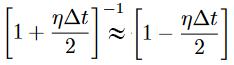
so that

with 320 points on the string, the solution rate is about 120 to 140 time-steps/second.
The linear wave equation code (uses Protothreads 1_3_2) also prints out the frame compute time and allows the user to wiggle one end of the string using an analog input from a potentiometer.
Video of the string end being wiggled.
One frame of the solution with Gaussian initial condtion is shown below.
Older documentation -- ignore
The library written for Arduino was ported to PIC32 by Syed Tahmid Mahbub, as explained on his excellent blog.
I hacked the demo program to be a little more focused on this course and to use Protothreads for multitasking.
The thread library was changed for this application to remove UART communication and debugging pin support.
More Protothread documentation is available.
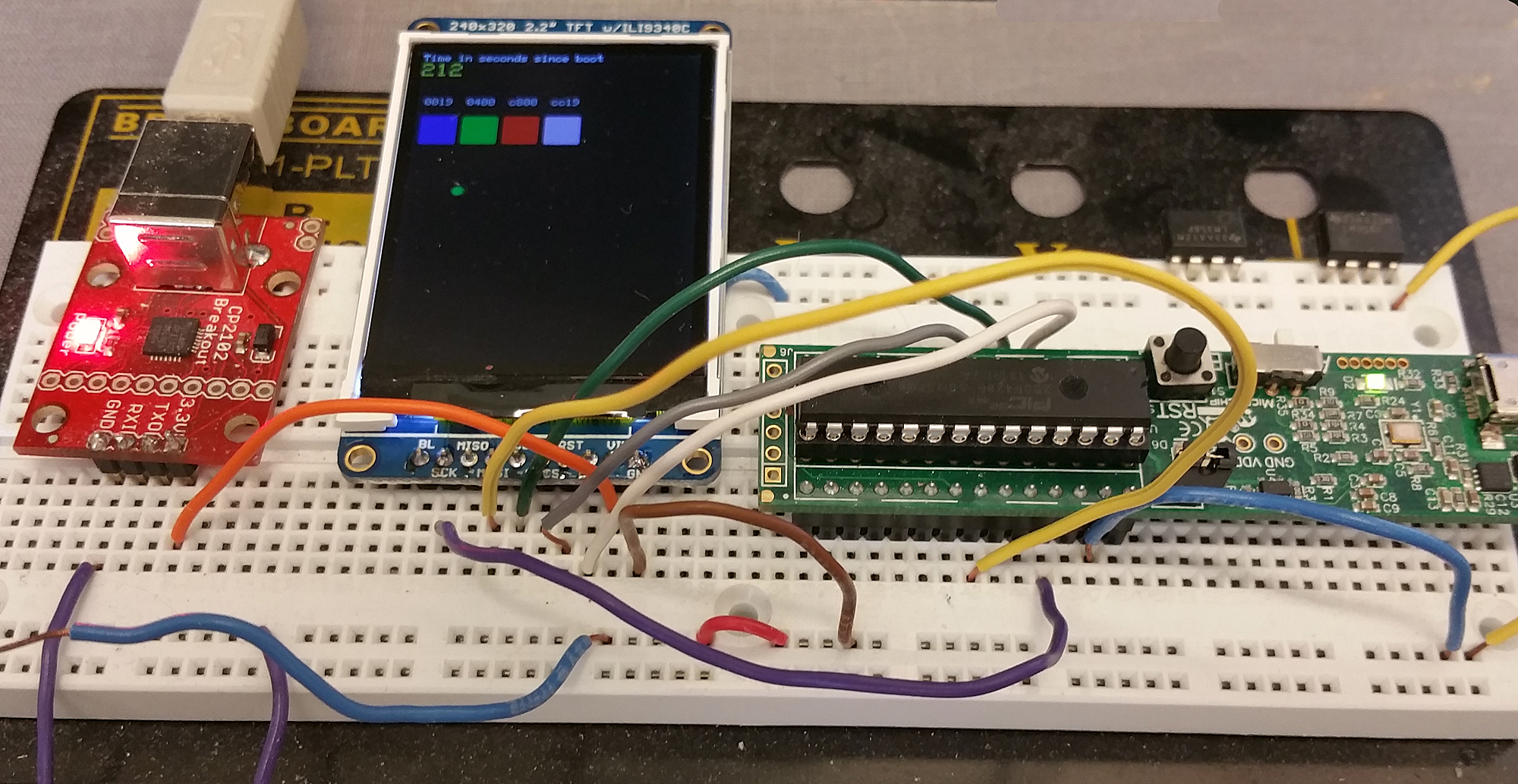
Connect the TFT display as shown below.Or as described in Tahmid's blog.
You can get Vdd from the via near the center of the MicrostickII as shown in the keypad section images.
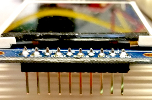
The third image shows the orientation of a properly soldered TFT header.

Download the TFT project ZIP file, refered to on the protothreads page.
A short video of the application generated by TFT_test_BRL4.c. This code can be substituted into the project.
There are spearate tft_master.c files for SPI channel one and SPI channel 2. An example which reads the AN11 analog input and draws the voltage on the TFT using the SPI2 master and Protothreads 1.2 is ZIPPED here.
Graphics Details
The Adafruit TFT color format is 16 bit:
Color examples:
A list of the available graphics routines is in tft_gfx.h with more explanation of parameters in tft_gfx.c
void tft_drawLine(short x0, short y0, short x1, short y1, unsigned short color);
void tft_drawRect(short x, short y, short w, short h, unsigned short color);
void tft_drawCircle(short x0, short y0, short r, unsigned short color);
void tft_drawCircleHelper(short x0, short y0, short r, unsigned char cornername,
      unsigned short color);
void tft_fillCircle(short x0, short y0, short r, unsigned short color);
void tft_fillCircleHelper(short x0, short y0, short r, unsigned char cornername,
      short delta, unsigned short color);
void tft_drawTriangle(short x0, short y0, short x1, short y1,
      short x2, short y2, unsigned short color);
void tft_fillTriangle(short x0, short y0, short x1, short y1,
      short x2, short y2, unsigned short color);
void tft_drawRoundRect(short x0, short y0, short w, short h,
      short radius, unsigned short color);
void tft_fillRoundRect(short x0, short y0, short w, short h, short radius, unsigned short color);
void tft_drawBitmap(short x, short y, const unsigned char *bitmap, short w, short h, unsigned short color);
void tft_drawChar(short x, short y, unsigned char c, unsigned short color, unsigned short bg, unsigned char size);
void tft_setCursor(short x, short y);
void tft_setTextColor(unsigned short c);
void tft_setTextColor2(unsigned short c, unsigned short bg);
void tft_setTextSize(unsigned char s);
void tft_setTextWrap(char w);
void tft_gfx_setRotation(unsigned char r);
void tft_write(unsigned char c);
void tft_writeString(char* str);    // This is the function to use to write a string
Drawing text
 To make is easier to format debugging messages, I wrote a short routine:
void printLine(int line_number, char* print_buffer, short text_color, short back_color)
that takes as input:
--
a line number: 0 to 31
--
a string of length 1 to 35 characters
--
text color
--
background color
The routine renders one text line of size=1 text on a vertically oriented screen.
The amazingly ugly display to the left shows five background colors
with the demo code cycling through five different text colors. A small change in the
code generates text of size 2 for those of us who have trouble seeing the smallest font.
void printLine2(int line_number, char* print_buffer, short text_color, short back_color)
For this function, line number range is 0 to 15
For capacitance measurement lab:
pins 4,5,6, 22 and 25 (RB0, RB1, RB2, MOSI1, SCLK1) pin 7 pin 18 pin 24Animation examples:
Example using fixed point arithmetic to bounce a ball with gravity and air drag.
This random diffusion example animates 3000 point particles, while profiling the execution time, and maintaining a elapsed time clock. The example uses an point drawing routine which takes about 10 microseconds/point to draw/erase. Most of that time is spent in SPI communication with the TFT display. For comparision, the NTSC TV code wirites a point in about 4 microseconds. Execution time for 3000 particles is about 60 milliseconds/frame, dominated by a draw and an erase for each particle. Zipped project (including the optimized point draw). CPU speed is 40 MHz.
However, cranking the CPU clock to 64 MHz, peripherial clock divider to unity, and the SPI divider to 2 enables drawing of 3000 particles in 37 milliseconds. It seems to work, but I suspect is of marginal stability because of white board bandwidth, and perhaps SPI maximum rate on the TFT display (Zipped project).
Copyright Cornell University October 10, 2019