PID control of a 1D helicopter
V. Hunter Adams (vha3@cornell.edu)
Note: This is a minor rewrite of an existing PIC32 lab for ECE 4760 created by Bruce Land.
Objective
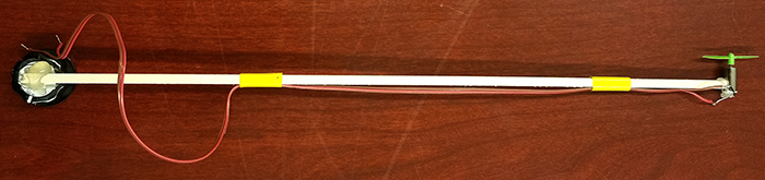
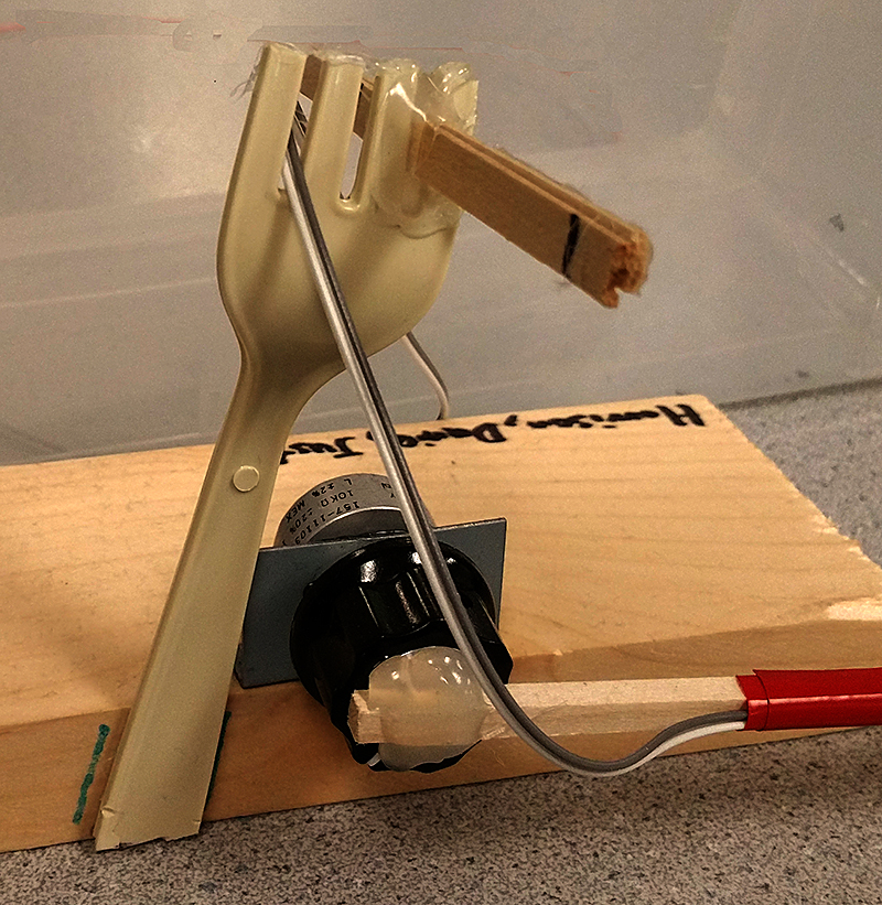
In this lab, you will construct and control of a one-degree-of-freedom helicopter. A small drone motor is rigidly attached to the end of a lever-arm, the other end of which is attached to a low-torque potentiometer. The drone motor can lift the arm, and the angle of the arm is measured by the potentiometer. The user can select a target arm-angle and a PID controller will drive the arm to that angle.
The target and measured angle are displayed on the oscilloscope and the user specifies new target angles through a serial interface to the PIC32. A demo is shown below.
Hardware overview
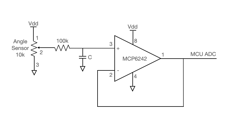
Angle sensor circuit
The angle sensor is a 10k potentiometer. The potentiometer output passes through an anti-aliasing low-pass filter (with R and C chosen as appropriate for a 1KHz sample rate) and into the MCP6242 opamp. This opamp is configured in as a unity-gain buffer, the output from which goes into the RP2040 ADC.
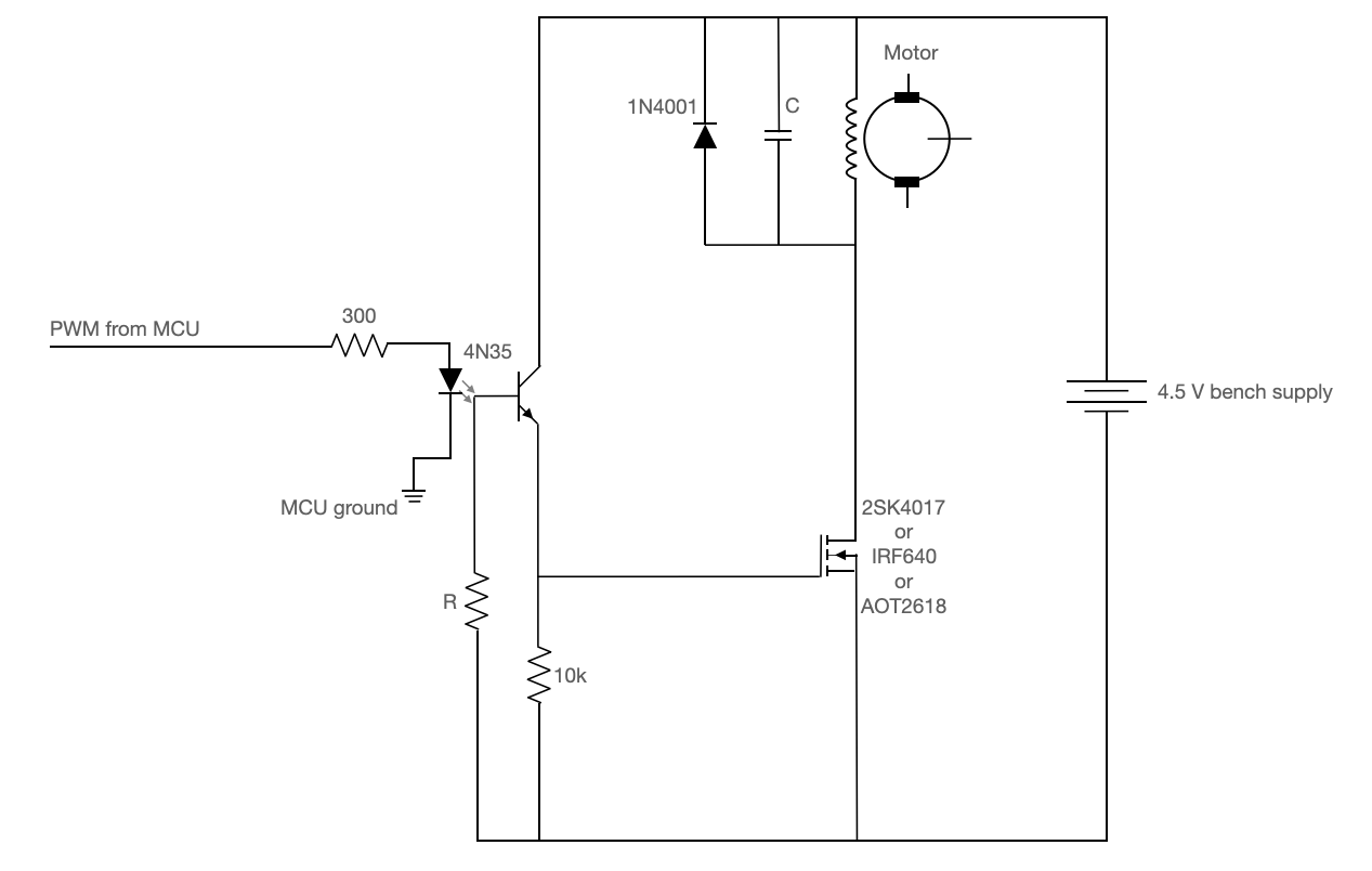
Motor circuit
The motor circuit must protect the microcontroller from the large $L \frac{dI}{dt}$ voltage spikes that come off of a PWM-driven DC motor. The 4N35 optoisolator completely isolates the MCU from the motor. The 1N4001 snubber diode provides a path to ground for reverse-polarity spikes coming off the motor, and the capacitor in parallel with the 1N4001 provides a path to ground for higher frequency noise. Some of the components in this circuit require some experimentation/trial and error. The resistor attached to the base of the 4N35 should be set for best falltime, probably ~1MOhm. The capacitor in parallel with the motor should be ceramic (electrolytics are too slow) and should start with a value ~0.1uF. If there is too much spike noise on the analog input, this value can be increased.
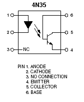
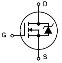
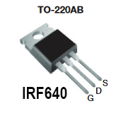
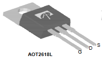
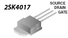
The pinouts for the 4N35 optoisolator and power MOSFET's are shown below. Note that it is the bandwidth of the 4N35 that constrains the PWM frequency. The bandwidth for this device is low, so we'll use a PWM frequency of about 1kHz.
 |
 |
 |
 |
 |
Mechanical construction
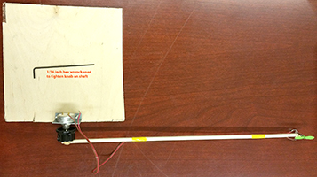
- Hot glue a motor to one end of the wooden beam. Note that the motor shaft should be at right angles to the rotation shaft of the knob.
- Roughen the knob surface using sandpaper. Be sure to remove the plastic film.
- Hot glue the other end of the wooden beam to the knob surface.
- Solder a pair of wires (from ribbon cable) to the motor and tape them to the beam. Note: Use only stranded wire peeled off from ribbon cable.
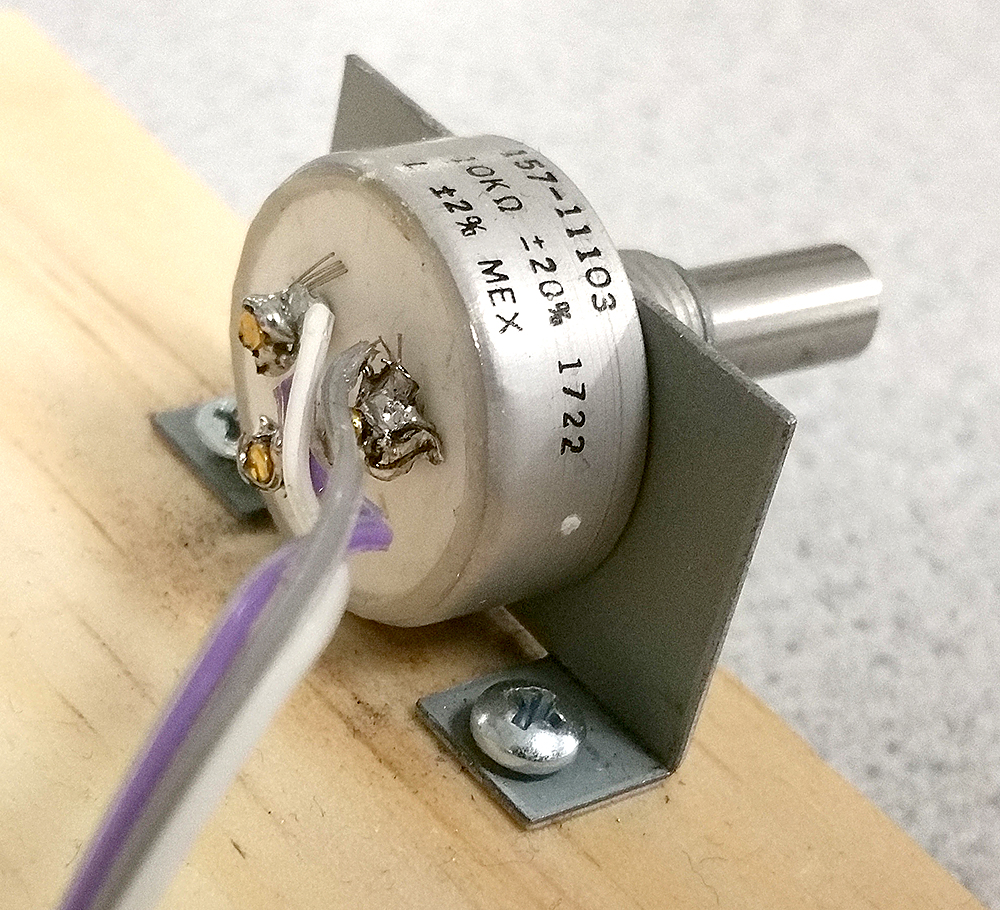
- Screw the potentiometer bracket to a chunk of wood big enough that you can use a book to weigh it down. Use #4 screws, as shown in the image below. Hot gluing the bracket to the wood will cost you 10 points in the lab.
- The potentiometer mounting hold on the bracket is slightly too small for the potentiometer sleeve. You will need to use the rat-tail (round) file to enlarge the hole.
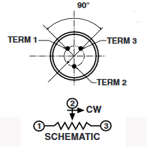
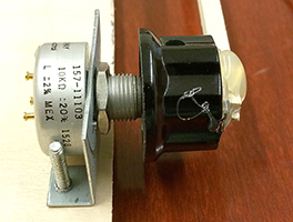
- When attaching the potentiometer to the mounting bracket, be sure that the locating pin (see data sheet) is in the appropriate sheet metal slot. The shaft on these potentiometers is freely rotating. Therefore, when attaching the beam to the potentiometer shaft you need to check the whole range of shaft motion for continuous resistance. I suggest adjusting the pot to 1/2 full resistance, then attach the knob to the potentiometer shaft with the wooden beam held in the horizontal position.
- Be sure to use pliers to tighten the potentiometer on the bracket.
- Use a 1/16 hex wrench to tighten the knob onto the shaft. Hot gluing the knob to the potentiometer will cost you 20 points on the lab.
- Solder three wires (from ribbon cable) to the potentiometer.
- Figure out how to put a rotation-stop on the beam so that it cannot go past vertical. A piece of wire works, or a coffee stir-stick, or a drinking straw, or a fork from Mattins.
Connections to PIC32
- As in lab 1, the SPI DAC you will use is the MCP4822. Use the examples shown on the Dev board page.
- Possible pin assignments for PWM, ADC, serial and control buttons are:
- An ADC channel for the angle sensor. Keep the ADC input line as far as possible from the SPI control signals. Perhaps A5 or A1.
- PWM via output compare unit, perhaps OC1 on RPB7
- Serial default for protothreads uses pins
PPSInput(2, U2RX, RPA1) ;
PPSOutput(4, RPB10, U2TX) ;
Be sure to uncomment#define use_uart_serialin the config file. - A button connected to Vdd through 300 ohm resistors, going to RA2 or RA3 with pulldown resistors turned on. Or use the port expander RY0 with pullup turned on.
Simulating the system
Bruce wrote a simulator for the system that is useful for tuning your PID controller.
Estimate the natural period and damping coefficient of the beam/motor/sensor that you built. You need these values for the system modeling and tuning. The natural period is approximately the simple pendulum natural period. $T = 2\pi \sqrt{\frac{L}{g}}$. Where L is the distance from the pivot to the motor, and g is gravitational acceleration. Using the DAC output to the scope, you can estimate the natural period. Also count the number of full cycles that the actual beam makes before it stops, and adjust the damping coefficient in the matlab code (DD) until the undriven pendulum matches the number of cycles. There are two versions of the matlab code. The first is a simulator using radian measure (with some guesses about motor thrust scaling). The second simulator uses angles measured in ADC units and motor control in PWM units, as shown below. The red line is the target angle.
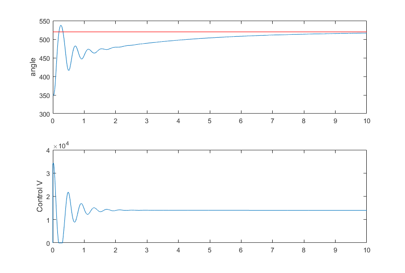
The ADC will probably be set up to measure the 10Kohm servo potentionmeter from zero volts to Vref, resulting in ADC units of 0 to 1023 representing the resistance range of 0 to 10kohm. According to the potientiometer datasheet, the 10K resistance range occurs over 340 degrees of rotation. The useful range of angles for this lab will be 180 degrees (hanging down to vertical above pivot point). The resistance range you can use is therefore 180/340*10Kohm=5.29K ohm, so the raw ADC range will be about 5.29/10*1024=542 counts for 180 degrees rotation. If we set up the potentiometer to read about 520 ADC counts when the beam is hovering at horizontal position, then when hanging straight down the resistance will be about 520-271=249, and when directly over the pivot point about 790.
Serial interface
Your system should be commanded via a Python-controlled serial interface, similar to that used in Lab 2. The list of requirements for this lab is given at the bottom of this document (in the weekly checkpoints and lab report section). Design a user interface that enables the user to demonstrate all of the requirements for this lab in a simple way.
I am not specifying all of the details for the interface to this lab assignment because it is the last one before the final projects. In the final project, you will need to think very carefully about usability and user interface. Consider this lab assignment to be guided practice thinking about how you want a person to interact with the system that you build. Do some experimenting. What sort of interface feels best to you and your group? Text entry? Sliders? Buttons? Some combination of these and other elements? Take this part of the project seriously!
See the Remote access page.
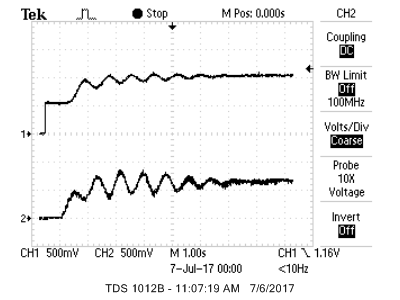
Data display
The DAC A/B channels will display beam angle and motor control on the scope. This will be useful for debugging and is required for the demo and the writeup. The top trace in the image below is the actual beam angle. You will note that the PID algorithm is poorly tuned in this image. There is an initial jump when the PIC32 is turned on with the beam hanging straight down, followed by oscillating convergence to the horizontal position. The bottom trace is the motor control signal used to drive the PWM. If you use a very large derivitive term in the PID controller to stabilize the oscillations, you may need to lowpass filter the motor signal to display on the scope. Consider using a first order IIR, digital lowpass, with a time constant of about 16 PWM samples, given by:
motor_disp = motor_disp + ((pwm_on_time - motor_disp)>>4) ;
Program organization
You may organize your program however you like. Here is a suggestion:
- Protothreads maintains the ISR-driven, millisecond-scale timing as part of the supplied system. Use this for all low-precision timing (can have several milliseconds jitter).
- Synthesis ISR uses a timer interrupt to ensure an exact 1kHz control rate.
- Reads the ADC to get the actual beam angle
- Runs the PID control loop at 1000/sec using the angle measurements from the potentiometer
- Sets a hardware PWM signal using output-compare unit to control the motor (see below for setup) using the command:
SetDCOC3PWM(pwm_on_time).
- Main sets up peripherals and protothreads then just schedules tasks, round-robin
- Thread 1
- Updates the TFT at ~10 times per second, only if you need status info
- Thread(s) 2-N
- Takes user input from the serial interface to setup PID parameters and the desired angle.
- The number of threads will depend on how you choose to contruct your user interface (e.g. sliders, text entry, buttons, etc.).
Weekly checkpoints and lab report
Note that these checkpoints are cumulative. In week 2, for example, you must have also completed all of the requirements from week 1.
Week one checkpoint
By the end of the lab session in week one of the lab you must have:
- The mechanical assembly finished and be able to control motor speed open loop, from the PWM output.
- Oscilloscope display of the actual beam angle and the low-passed motor command signal using the two channel DAC, as described below. This is critical for debugging.
- Finishing a checkpoint does NOT mean you can leave lab early!
Week two checkpoint
By the end of the lab session in week two of the lab you must have:
- Full closed-loop control of the motor.
- Serial command interface to set PID parameters.
- Finishing a checkpoint does NOT mean you can leave lab early!
Week three assignment
- Measure the angle of the beam supporting the lift-motor
- Format the set angle and PID parameters to display appropriate messages on the TFT display
- At any time, take commands from the Python serial interface to:
- Set the desired beam angle
- Set the PID proportional gain
- Set the PID differential gain
- Set the PID integral gain
- The new values should take effect immediately
- One set of coefficients should produce stable behavior over the range of desired hover angles
- Use a PID control algorithm to control the speed of the motor by producing a PWM drive to the optoisolator. PWM setup example.
- Tune the PID algorithm so that you can change the angle of the beam quickly and accurately without excessive angle oscillations.
- The user should be able to enter a desired hover angle and the motor should quickly change the beam to the new angle. The initial angle of the beam should be around -1.57 radians (hanging straight down).
- Display the motor control value (not the raw PWM signal) on the scope using channel B of the DAC. Noise control on this signal is essential. If you cannot see the shape of the control signal, you will not get credit for this feature! You may need to combine DSP and analog filtering, depending on exactly how you build the circuit.
- Display the actual beam angle, from the angle sensor, on the scope using channel A of the DAC. If this signal is noisy, you need to find out why! Poor wire routing, loose connections, and motor noise are all posibilities. A noisy input makes the control PID algorithm very hard to tune.
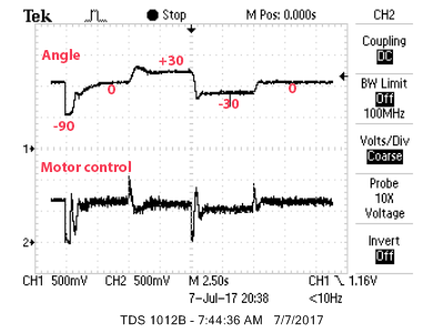
- When a button is pushed (not the reset button), the beam should go through a quick sequence of defined angle changes, using the current set of PID parameters:
- Before time=0, while holding the button, the beam should be hanging vertically down (motor off)
- When the button is released at time=0, target angle should be set to horizontal
- At time=5 seconds, target angle should be set to approximately 30 degrees above horizontal
- At time=10, target angle should be set to approximately 30 degrees below horizontal
- At time=15, target angle should be set to horizontal
You will demo all of the features above to a course staff member. You program should not need to be reset during the demo.
Lab report
Your written lab report should include the sections mentioned on the policy page, and:
- A schematic of the circuit you built
- Scope screen dumps of typical two-trace: (1) motor-control and (2) actual angle. Include the demo sequence of four angles, as shown below
- A summary of the accuracy of your measurements. How accurately can you measure the angle?
- How you selected the three PID gains.
- What are the maximum/minimum angles that produce stable behavior for your PID gains?
- What are the settling times at different angles?
- A heavily commented listing of your code.