Cornell University ECE4760
Development Boards
PIC32MX250F128B
Introduction
There are two target boards which were created by Sean Carroll:
---
The first is large and intended to be used for the lab exercise part of the course.
---
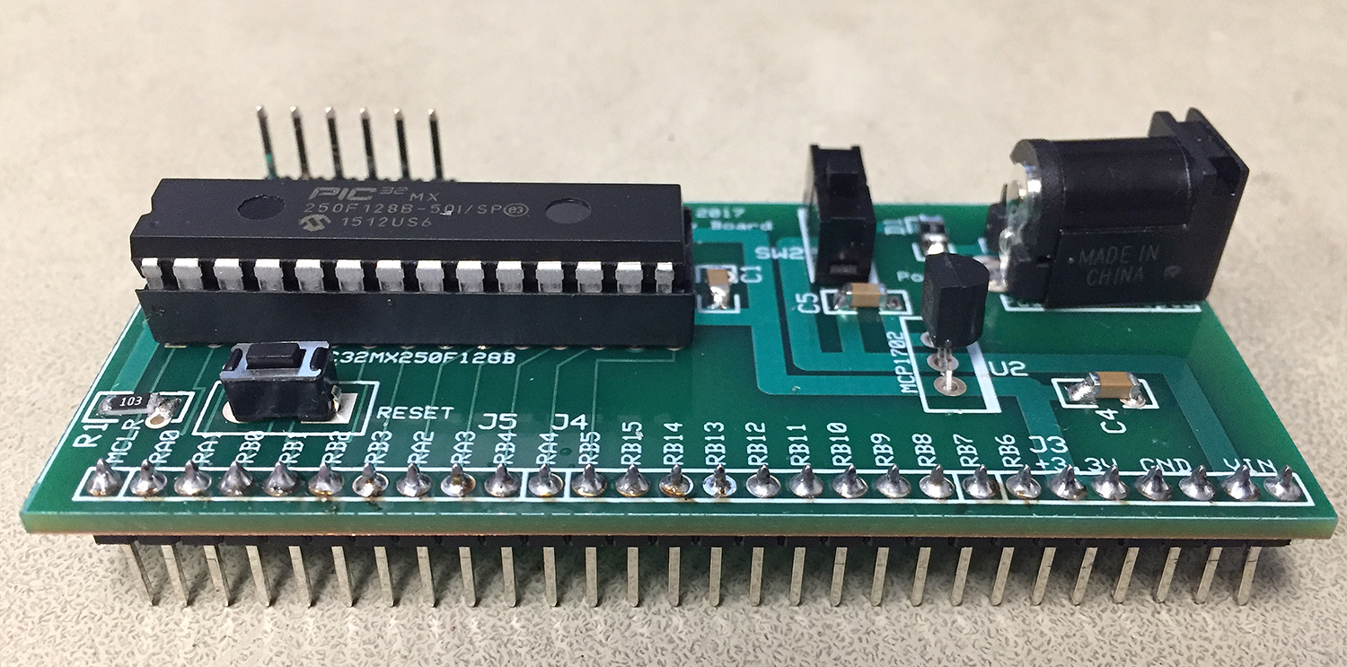
The second board is small and is intended to be a CPU carrier for final projects and other space-limited uses.
Both boards are programmed by tapping the programming signals from a Microstick2 (see below).
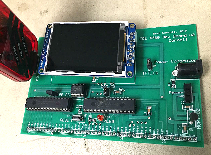
Sean Caroll's Big board (SECABB)
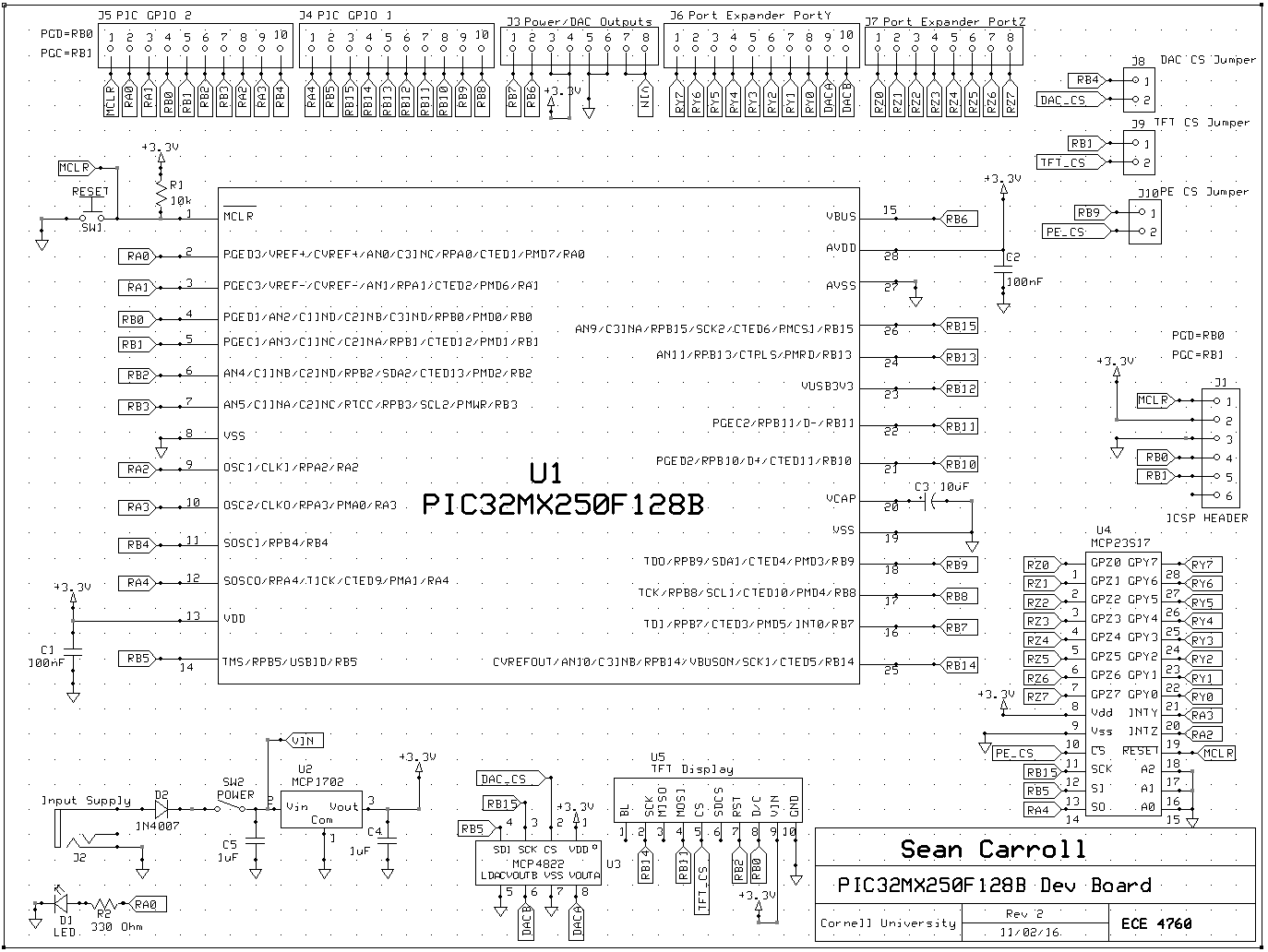
The SECABB features a port expander, DAC, TFT header-socket, programming header-plug, and power supply.
See below for specific code examples of each device on the big board.
Version 2 SECABB
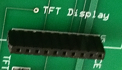
-- Assembly instructions for the v2 board : Programming header-plug (J1)  : TFT header-socket
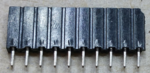
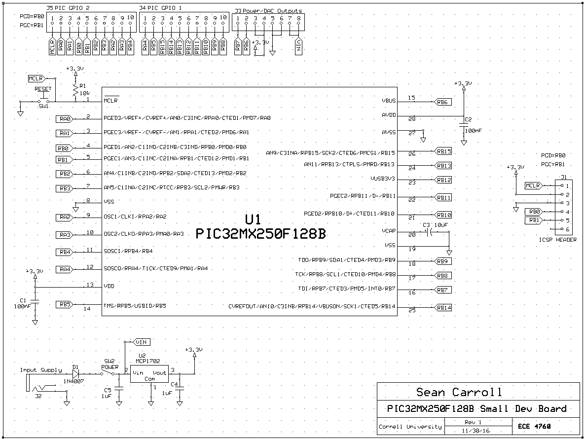
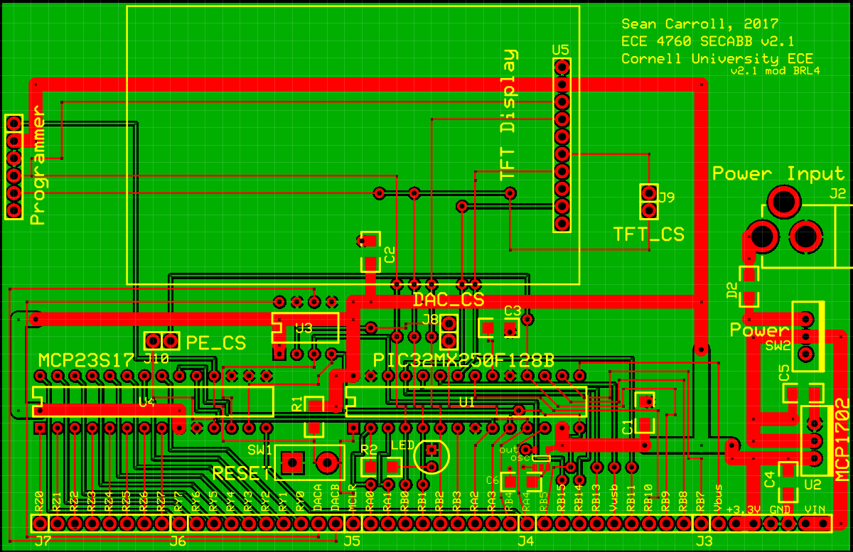
-- SECABB v2 schematic and layout (ExpressPCB format)
-- Using the TFT LCD, but see below for specific examples on the big board
-- SPI and DAC, but see below for specific examples on the big board
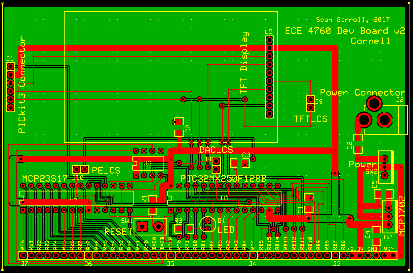

Big Board SECABB v2 silk screen errors.
--Edge connector pin marked RB6 -- RB6 Does not exist on this package! Silk screen should read Vbus.
--Edge connector pin marked RB12 -- RB12 Does not exist on this package! Silk screen should read Vusb3.3.
--LED D1 outline -- Silk screen should have flat side should be oriented toward PIC32.
PIC32 i/o pins used on big board, sorted by port number. Any pin can be
recovered for general use by unplugging the device that uses the pin.
SPI chip select ports have jumpers to unplug.
----------------------------
RA0 on-board LED. Active high.
RA1 Uart2 RX signal, if serial is turned on in protothreads 1_2_2
RA2 port expander intZ
RA3 port expander intY
RA4
PortExpander SPI MISO
-----
RB0 TFT D/C
RB1 TFT-LCD SPI chip select (can be disconnected/changed)
RB2 TFT reset
RB4 DAC SPI chip select (can be disconnected/changed)
RB5 DAC/PortExpander SPI MOSI
RB6 !!! Does not exist on this package!!! (silk screen should read Vbus)
RB9 Port Expander SPI chip select (can be disconnected/changed)
RB10 Uart2 TX signal, if serial is turned on in protothreads 1_2_2
RB11 TFT SPI MOSI
RB12 !!! Does not exist on this package!!! (silk screen should read Vusb3.3)
RB14 TFT SPI Sclock
RB15 DAC/PortExpander SPI Sclock
----------------------------
Version 2.1 SECABB
Version 2.1 SECABB (expresspcb format) Image.
Changes from Version 2:
-- Fixed silk-screen errors --LED D1 is correctly oriented, and RB6, RB12 renamed
-- Pads for external crystal: sot23 oscillator for either main oscillator input (8 MHz) or RTCC oscillator (32768 Hz)
-- C6 should be mounted ONLY if an oscillator is added. But put the SOT23 part on first.
-- Output via for oscillator is too small for a wire. Be careful soldering it.
Software for SECABB
--Current Protothreads version is 1_3_2.
See the Protothreads page for details on 1_3_2 and the test code SECABB_test_1_3_2.c
Download this ZIP file to get all the libraries and the following code examples in one place.
You should be able to delete the test code from the project and then include any of the following examples.
To port any other examples you will need to EDIT the config and protothreads #include files to
config_1_3_2.h and pt_cornell_1_3_2.h but everything else should work.
Previous version codes which have been ported and tested in this version includes:
- TFT_test_BRL4.c
-- Simple SECABB test example (no port expander, no serial connection) below
- DDS_Accum_Expander_BRL4.c for 2019 lab 1.
Read the description! (example 1 in the Sound page)
- SECABB_simple_protothreads_test_1_3_2.c
DAC ISR, keypad, LED, PT_SPAWN
- Spawn a thread simple example
prints the time on the TFT by spawning a thread, blinks
- Spawn serial communication example
threads to blink and for serial communication to terminal
- Simple serial console command parser
threads blink, write time to TFT, parse serial commands.
-----------------------------------------------------------------------------------------------------
- TFT_animation_Accum_BRL4.c -- See TFT display page
- TFT_KEY_test_BRL4.c
-- Keypad example below using PIC32 i/o ports (but use example 2 above)
- TFT_ADC_read.c
-- ADC example description below. Most useful for lab 2
- TFT_ADC_read_SCAN.c
-- ADC multichannel example description below. Most useful for lab 2
- TFT_KEY_expander_shift_BRL4.c
-- Keypad using Port Expander below (but use example 2 above)
- Serial_1_2_3_test_all.c
-- Board test example (with port expander, and serial connection) below.
-- Most useful for setting up lab 3
- Timer_capture_signal_gen_1_3_2.c -- input capture example for 2018 lab 1 (ZIP)
Descriptions of examples, but USE the code above!
-- Board test example (no port expander, no serial connection) uses Protothreads 1.2.1 to drive the TFT-LCD, on-board LED and
DAC.
The example displays some graphics, blinks the LED at 0.5 Hz and outputs a 24.4 Hz sawtooth from the DACA (DAC channel A) output pin. SPI channel 1 runs the TFT, SPI channel 2 runs the DAC. Pin RA0 is attached to the LED.
(code, ZIP) Be sure to attach the chip-select jumpers for the TFT and DAC!
-- Board test example (with port expander, and serial connection) uses Protothreads 1.2.3 ( or 1_3_2) to drive the TFT-LCD, on-board LED,
DAC, UART, and port_expander.
The example displays some graphics, blinks the LED at 0.5 Hz and outputs a settable frequency DDS sine wave from the DACA (DAC channel A) output pin. SPI channel 1 runs the TFT, SPI channel 2 runs the DAC and the port_expander. The shared channel 2 takes some care because the DAC drive code is in an ISR, and because neither the port_expander library or DAC play nicely with SPI channel setup. Pin RA0 is attached to the LED. The port_expander is connected to a keypad (see below). The UART requires a serial connection as described below.
(Code, project ZIP, config_1_2_3.h, pt_cornell_1_2_3.h, port_expander_brl4.c and port_expander_brl4.h libraries. See below for connection of port expander to a keypad).
Be sure to attach the chip-select jumpers for the TFT, port_expander and DAC!
-- DAC/DDS example uses the same environment as above. Download the ZIP and substutute in the source code which uses direct digital synthesis to generate a sine wave. Note that the ISR toggles port pin A0 for testing. The DAC output is attached to two header pins marked DACA and DACB. To profile ISR execution time, I instrumented the ISR to record execution time elapsed from the hardware timer-match event that triggered the ISR. Then I added a floating multiply or a integer mulltiply and shift. The times for total ISR time are:
- No multiply, 123 cycles. Context switch into ISR is 23 cycles.
- One floating multiply, 269 cycles.
Context switch into ISR is 46 cycles.
- Two floating multiply, 367 cycles. Context switch into ISR is 46 cycles.
- Integer multiply and shift, 150 cycles.
Context switch into ISR is 32 cycles.
- Timing test source code. Conclusion: Avoid floating point in ISR!
-- Animation example uses the same environment as above. Download the ZIP and substutute in the source code which uses fixed point arithmetic (fix16) to compute a bouncing ball with gravity and drag. Changing to the XC32 built-in fixed point type _Accum makes a slightly cleaner code.
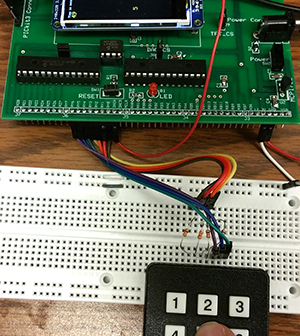
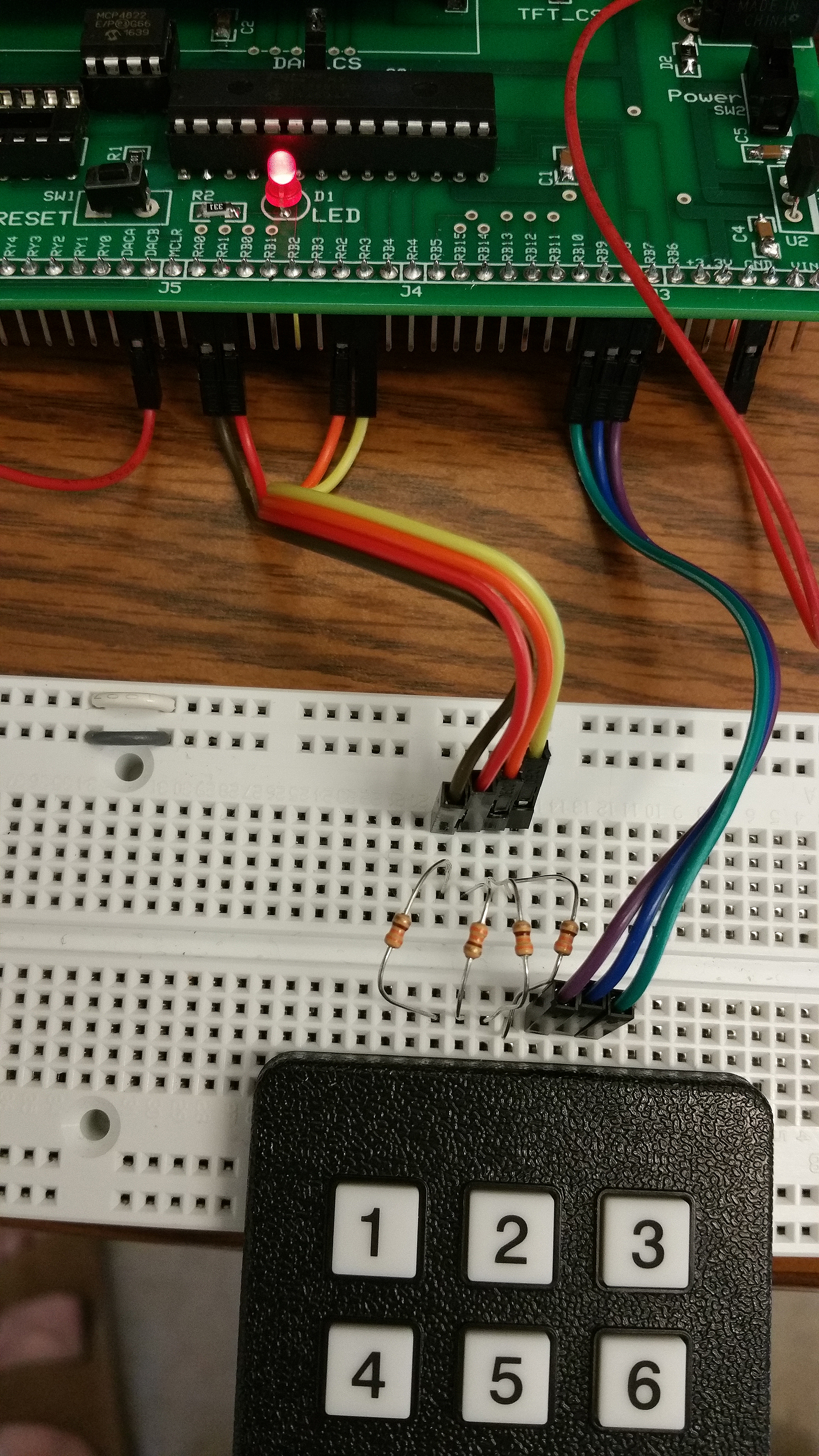
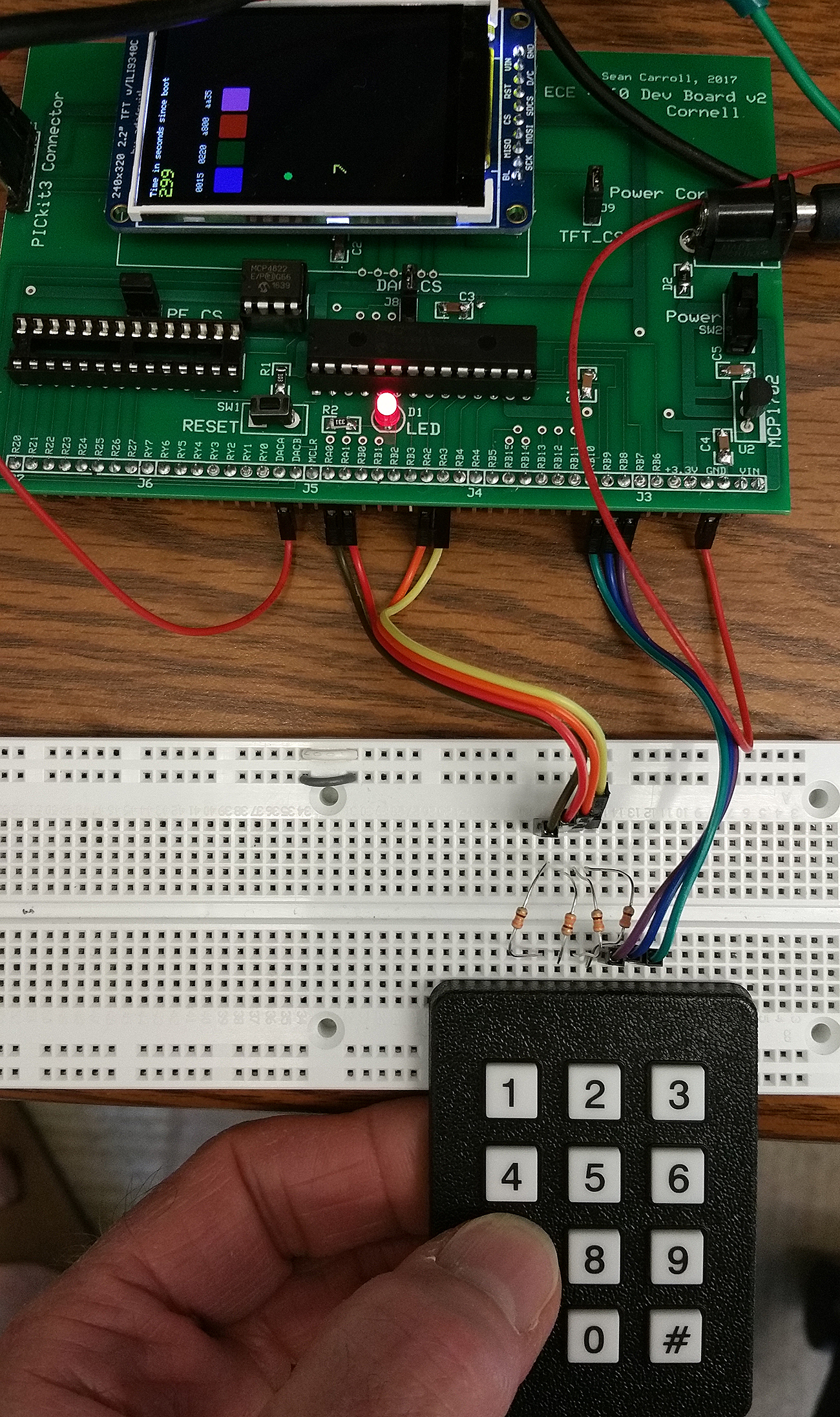
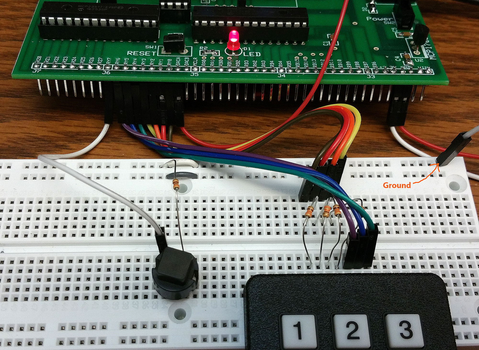
-- Keypad example uses the same environment as above. Download the ZIP and substutute in the source code which implements the keypad scanner using the big board pinout. Connections and pressing button 7 are shown below. Note that the internal pull-down resistors are turned on, so no external 10k resistors are needed. Occasionally, the wiring to the keypad is too long, or the solderless board capacitance is too high, so stretching the scan pulse may help to produce a stable reading. This version has a 1 microsecond stretched pulse.


-- ADC example uses the same environment as above. Download the ZIP above and substutute in the source code which implements display of the ADC raw value and voltage on the TFT. The channel read is AN11, which is mapped to RB13 on the big board. Be sure that any voltage you connect has a 1k resistor in series and is in the range 0 to 3.3 volts at all times!
-- ADC multichannel example uses the multichannel scan to read two or more channels. Weirdly, in the ADC setup, you specify the channels you do not want to scan, then turn on the scan and autosample options. You also need to set ADC_SAMPLES_PER_INT_x, where x is the number of channels to be scanned, even if you do not turn on ADC interrupts. When you read the ADC buffer the values of the enabled channels will be in consecutive buffer locations, sorted by enabled channel number. For example if you set up the scan to read AN5, AN1, and AN11, then buffer locations 0,1,2 will hold the values of AN1, AN5, and AN11 respectively. The code requires protothreads 1_2_2a (explained below in the serial section, ZIP) because it prints the values of AN5 and AN11 on the TFT and on the serial terminal. The code will work with protothreads 1_2 if you comment out the serial thread.
-- Framed SPI example See example 1 on SPI page.
-- Serial Console, Port Expander, DAC/DDS, TFT
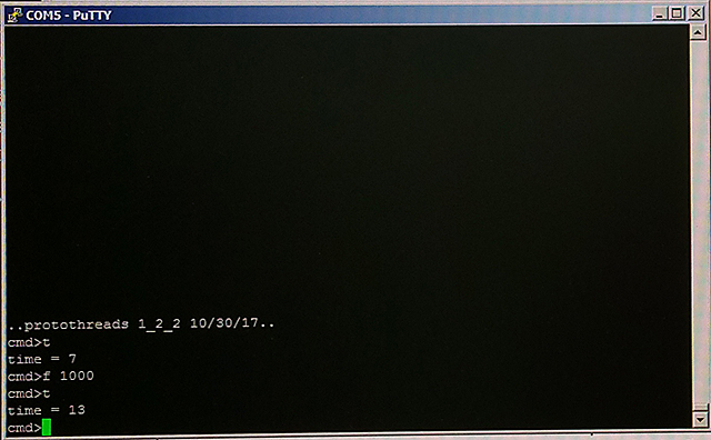
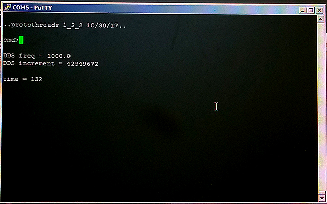
This example adds a serial console on the PC to a keypad scanner using the port expander, a DDS generated sinewave on the DAC, and with TFT test code. The serial console uses UART2 to connect to PuTTY on the PC using a UART-to-USB cable. On the big board, the default assignment for the U2RX pin is RPA1, and for U2TX is pin RPB10. These are specified in the protothreads 1_2_2 serial initialization section (just after line 750). The ZIP file includes protothreads 1_2_2, modified for the big board, and it includes the port expander library, as well as the TFT library (CODE, ZIP) A typical serial PuTTY window is shown below communicating with the PIC32. It is possible to produce a more structured screen by setting the cursor to fixed positions on the screen. The second image shows the effect of forcing the command prompt to line 4 and the results of the command to three lines just below (code).
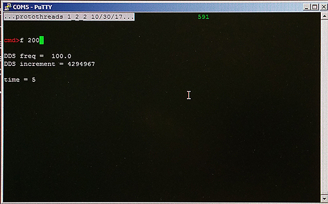
-- A slightly modified version of protothreads 1_2_2, designated 1_2_2a, is set up for faster baud rate to serial, better handling of text input character counter, and splash-line with text formatting. The third image uses the slightly modified protothreads to render reverse video and color text. (code, ZIP). The input character count is necessary because two threads use the UART and the coordination is handled by application code, not by the threader. A timer thread writes a second-count in green while the serial input thread is mostly waiting for user input. For cursor positioning, line counts start at one, not zero. So the macro cursor_pos(1,1) sets the cursor to the upper-left corner of the screen. The baud rate is set to 115200 in config_2_2_2a, but may need to be set lower for reliable communication.
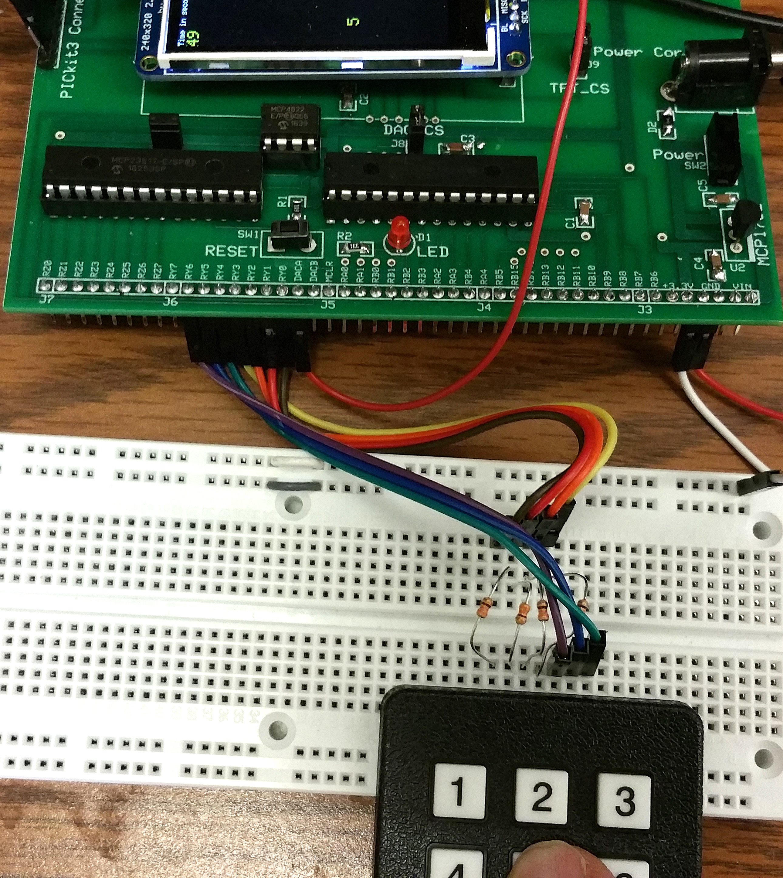
-- Keypad using Port Expander example uses a new environment which includes the port expander library (details below). Download the ZIP and the source code which implements the keypad scanner using the port expander on the big board pinout shown on the left below. Included in the ZIP file is the portexpander.h and portexpander.c corrected and extended for the big board. This example adds to Sean's version by allowing the DAC and port expander to share an SPI channel without conflict (except timing). The port expander docs name the two 8-bit ports A and B, but to avoid confusion with the PIC ports of the same name, Sean refers to the expander ports as Y and Z on the big board and in the interface library. The keypad is connected to port pins Y0 to Y6. Y0 to Y3 are driven as outputs, while Y4, Y5 and Y6 are inputs with pullups turned on (there are no pulldowns on the expander). The scanner logic has to be modifed for active-low outputs, but the scanner output is the same as before. The scanner returns 0 to 11 for a valid key, and -1 if there is no valid keypress. Since the DAC is driven from an ISR (and is on the same SPI channel), and since the keypad takes several SPI interactions to complete a write-read cycle, it is necessary to define a critical section in the code to disable the ISR for a few microeconds while write/reading the port expander SPI channel. Two of the port expander's Z port pins are used to test bitwise i/o functions.
Keypad Scanner/Decoder:
(1) Shift one zero value (active low) through the 4 input lines ( Y0 to Y3).
(2)
Y4, Y5 and Y6 all high implies no button push -- bit-wise and the Y port with 0x70 to isolate the three keypad input bits.
Ignore the shift key (Y7 input) because pressing the shift key alone is not valid.
(3) If the
result of the and is not equal to 0x70, then there must have been a button push.
(4) If there was a button push start trying to match it to the scan table.
(5) Scan table includes shift key input and returns -1 if there was no (or an illegal) keypress.
--
The image on the right includes an extra switch which acts as a shift-key for the keypad and which is connected to Y7 (with pullup turned on). The source code supports 24 unique button codes and displays them on the TFT for testing using the printline function. The switch is connected through a 300 ohm resistor to ground, when pushed, and is pulled-up internally. If you float the input, the code behaves in the same way as the keypad with no shift key attached.

Port Expander Details. Sean Carroll wrote support code for a port expander which gives the PIC32 16 more i/o lines, running at SPI rate of around a transaction per microsecond. Sean Carroll structured the code to look as much like the PLIB commands for ports A/B as possible. There are two ports named Y and Z, each with 8 bits of bidirectional general i/o.The example above that reads the keypad using the big board and displays the result on the TFT-LCD uses a slightly modified portexpander.c file from Sean's version to accomodate board connections and simultaneous use of the DAC, which shares an SPI channel. The port expander max SPI clock speed is 10 MHz, so the DAC is running slower also.
(This is Sean's version with examples of using interrupts, but do not use the pin layout with the big board.
Using the Port Expander and ZIP code (Sean Carroll))
Available commands:
| Function |
Description
|
| initPE(); |
Initialize the port expander on the big board.
Must be used before any other command in this table. |
mPortYSetPinsOut(bitmask)
mPortZSetPinsOut(bitmask) |
Make the pins on the port outputs. Example:
mPortYSetPinsOut(BIT_7 | BIT_6); |
mPortYSetPinsIn(bitmask)
mPortZSetPinsIn(bitmask) |
Make the pins on the port inputs. Example:
mPortZSetPinsIn(BIT_0 | BIT_1); |
mPortYEnablePullUp(bitmask)
mPortYDisablePullUp(bitmask)
mPortZEnablePullUp(bitmask)
mPortZDisablePullUp(bitmask) |
Turn on/off the pullup resistors for an input.
mPortZEnablePullUp(BIT_0 | BIT_1); |
mPortYIntEnable(bitmask)
mPortYIntDisable(bitmask)
mPortZIntEnable(bitmask)
mPortZIntDisable(bitmask)
|
Enable/disable interrupt generation from in input. See Sean's example for more details.
mPortZIntEnable(BIT_0 | BIT_1) |
| setBits(port, bitmask) |
Set selected bits in one of the two ports.
port is either GPIOY or GPIOZ
setBits(GPIOZ, BIT_0) ; |
| clearBits(port, bitmask) |
Clear selected bits in one of the two ports.
port is either GPIOY or GPIOZ
clearBits(GPIOZ, BIT_0) ; |
| toggleBits(port, bitmask) |
Toggle selected bits in one of the two ports. **
port is either GPIOY or GPIOZ
toggleBits(GPIOZ, BIT_1) ; |
| readBits(port, bitmask) |
Reads selected bits of an 8-bit port. Note that reading pins set to output reads the output value on the pin. **
port is either GPIOY or GPIOZ
readBits(GPIOZ, BIT_0 | BIT_1)
(You
can also read the output latch registers OLATZ or OLATY) |
| readPE(port) |
Reads an 8-bit port. Note that reading pins set to output reads the output value on the pin.
port is either GPIOY or GPIOZ
readPE(GPIOZ); |
| writePE(port, data) |
Writes an 8-bit port.
port is either GPIOY or GPIOZ
writePE(GPIOY, 0xaf); |
start_spi2_critical_section
end_spi2_critical_section
|
IF you use an ISR which references any SPI2 function, then you must write these. Mine work for a timer2 ISR. **
#define start_spi2_critical_section INTEnable(INT_T2, 0);
#define end_spi2_critical_section INTEnable(INT_T2, 1);
The names of the interrupts are in Table 8-1 in PLIB Guide |
** added by Bruce
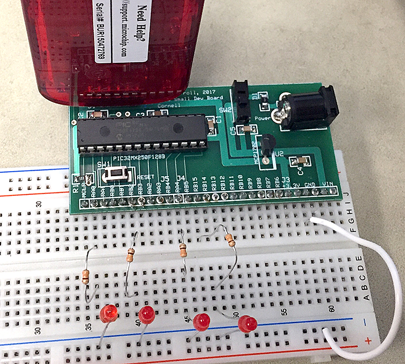
Sean Caroll's Little board (SECALB)
The small board is stripped down to just a MCU and power supply.
The intention is that this board can be built into projects easily.
-- Assembly instructions.
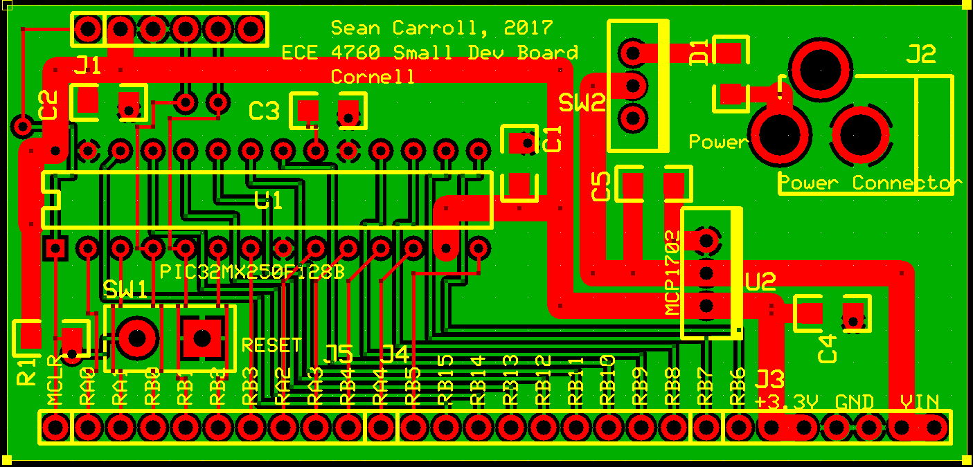
-- Small board schematic and layout (ExpressPCB format)
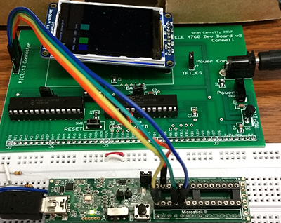
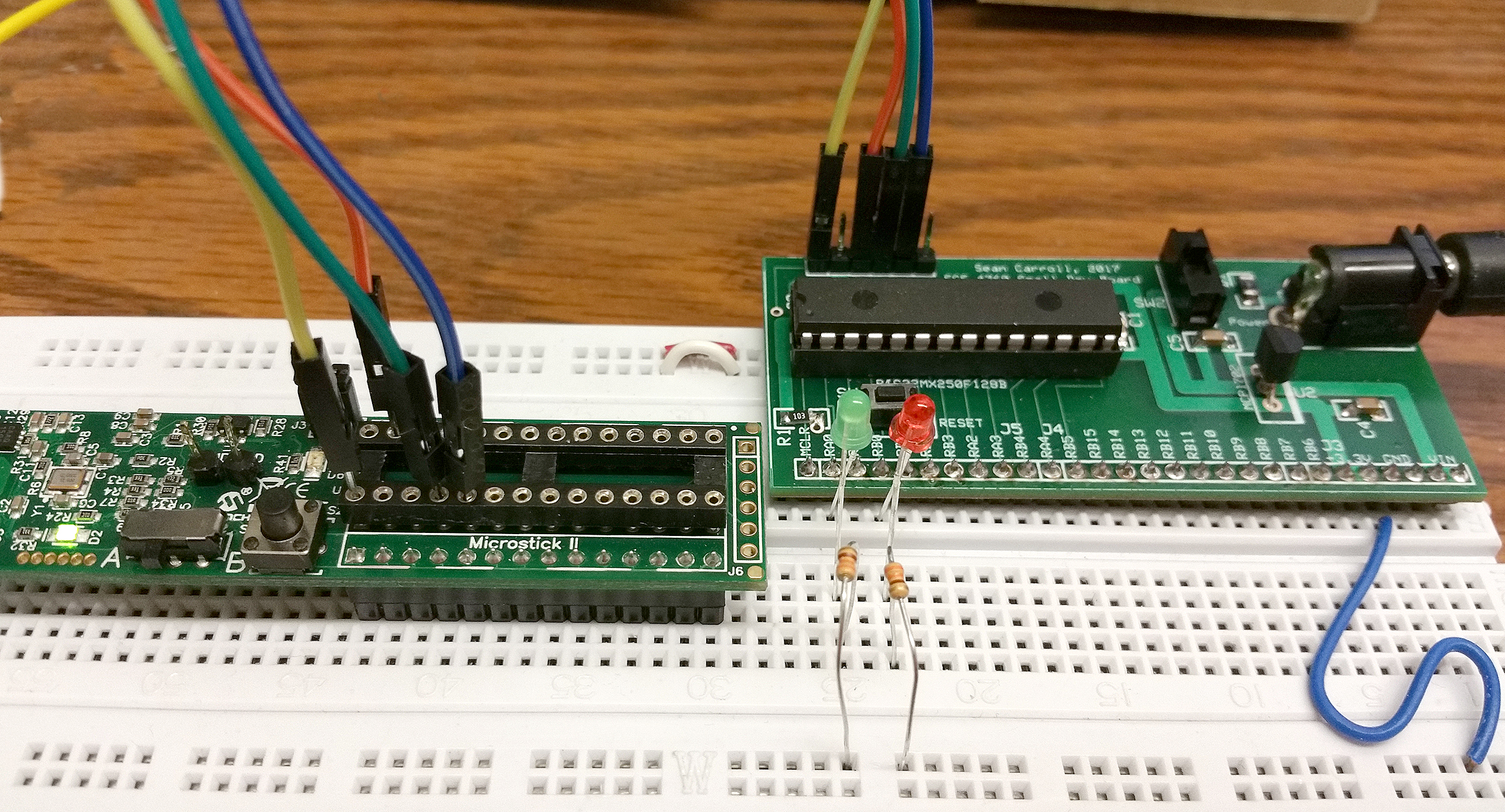
An example uses Protothreads 1.2.1 to drive two LEDs connected to RA0 and RB0, see picture in the
microstick2 programming section below.
(code, ZIP)

Silk screen errors :
RB6 !!! Does not exist on this package!!! (silk screen should read Vbus)
RB12 !!! Does not exist on this package!!! (silk screen should read Vusb3.3)
Microstick2 as a programmer
The connections to the microcontroller socket on the Microstick2 act like the
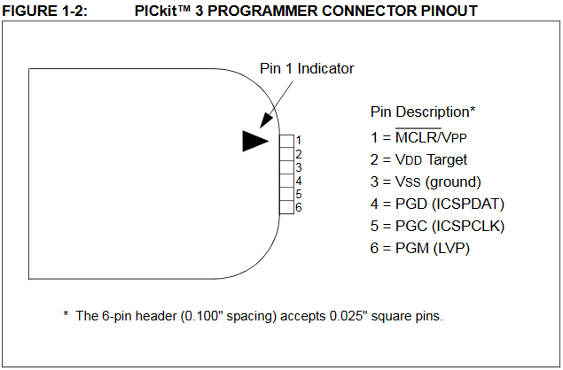
standard programming signals from the PICKIT3, which was used to develop the boards you will build.
On both boards, J1 marks pin1 of the 6-pin ICSP header-plug.
Note that for the pins shown, the programming selector switch on the Microstick2 must be set to position A.
| Signal |
PICkit3 (ICSP)
connector on board |
Microstick2
DIP Pins |
| MCLR |
1 |
1 |
| ground |
3 |
27 |
| prog data (PGD) |
4 |
4 |
| prog clock (PGC) |
5 |
5 |
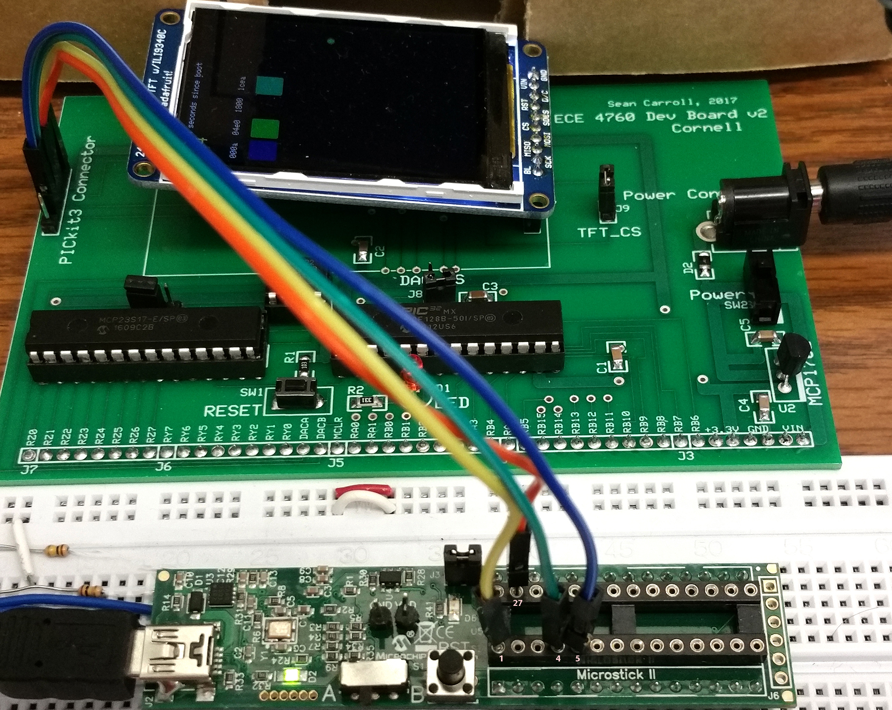
A wiring example is shown below. Note that pin 1, MCLR, is only available on the Microstick2 DIP socket as shown.
Also note that the programming selector switch on the Microstick2 must be set to position A.
When you click on the small images, you will get enlargments with the pin numbers indicated.
In general, the microstick programmer should be connected to USB power and the development board
to its own 5 volt power source. There are a couple of special cases which are noted here only because
some people have tried them and caused failures.
(1) For systems that do not draw too much power, you could attach the VDD output from the
Microstick programmer to pin 2 of the programming header to provide power to the target board,
BUT ONLY IF you do not connect any other power to the big or small board.
(2) If the microstick programmer is attached to the development board,
then the microstick must have USB power for the target PIC32 to boot.
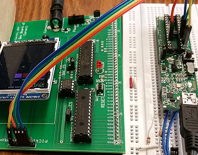
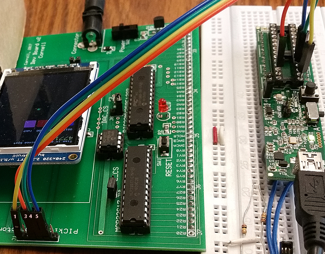
Another example with the small board.

Resources
Copyright Cornell University
March 6, 2020