You will produce a sinewave generator which is controlled by a 16-key keypad and which shows the frequency on a LCD display. The sinewave generator will be based on lab exercise 4.
Procedure:
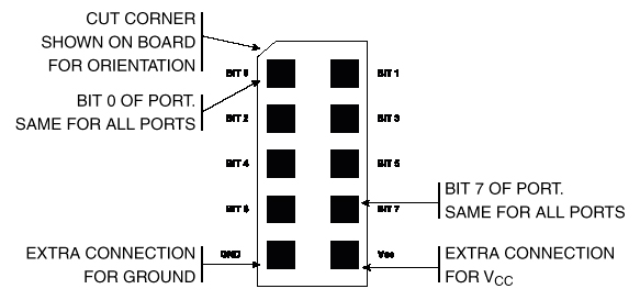
The STK-200 board has different pinouts on the header connectors. Pin 9 (see below) on the port connectors is Vcc, not ground as it was on the green boards.
This project uses the STK-200 board. Note that the cpu is an AT90S8535. The main differences from the 4414 are:
The Keypad:
You will need to get user input from a keypad with the following configuration. Demonstration keypad scanning code is here.
Pin 1  -- row 1 2 3 A
Pin 2  -- row 4 5 6 B
Pin 3  -- row 7 8 9 C
Pin 4  -- row * 0 # D

Pin 5  -- col 1 4 7 *
Pin 6  -- col 2 5 8 0
Pin 7  -- col 3 6 9 #
Pin 8  -- col A B C D

(a) Each switch shorts one row to one column.
(b) Each pin should be connected to one
    bit of an i/o port.
(c) The i/o port pins will be used both
    as inputs and outputs. When they are inputs,
    they should have the pullup resistors
    activated.
The Liquid Crystal Display (LCD):
A 16 character, one line (16x1), LCD display will be the output for your capacitance meter. The display we are using has an industry-standard interface. A data sheet for a similar display shows the connections. There are several aspects of the display you should note:
LCDpin 	Connection
------  ----------
1	gnd
2	+5 volts - From a port pin
3 	trimpot wiper (the ends of the trimpot go to gnd and +5)
4	PortD6
5	PortD5
6	PortD4
7-10	no connection
11	PortD0
12	PortD1
13	PortD2
14	PortD3
Write a program which will:
When you demonstrate the program to a staff member, you should exercise the keyboard commands and show that the frequency displayed on the LCD is correct.
Your written lab report should include: