EE 476: Laboratory 1
Introduction to the lab hardware/software.
Introduction.
This assignment introduces you to the software and hardware development tools
you will use this semester to work with the Atmel AT90-series microcontroller
chips.
Hardware
The hardware you will
be using to support the AT90-series is the Flash MCU evaluation board, a small
board providing:
- A target AT90-series microcontroller (mcu) with onboard flash program memory.
- A programmer for the target flash memory, including a parallel connection
to a PC.
- Eight general pushbuttons, eight LEDs and a RESET button.
- A serial connection for applications.
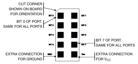
- Connectors for bringing out the microcontroller signals to user-designed
peripheral equipment. Note that there is no protection on these lines. You
are connecting directly to the mcu. Prudent design suggests you might want
to use buffers when you are uncertain of voltage levels or other conditions.
The pin definitions for the connectors are shown below. The inner squares
represent pins. The outer border is a white line surrounding the plug.
A small power supply
provides power to the development board.
Most lab exercises will involve using a prototype
board.
A separate power supply
will be used for powering the prototype board.
Software
Software you will use consists of:
- The AVR assembler which takes
assembler source code and produces an object file, a hex file and a listing
file.
- AVR Studio which simulates the
execution of an object file.
- AvrProg which downloads the
hex file to the target mcu.
- A locally written
keyboard monitor program.
- A couple of weeks from now, we will be using the CodeVisionC C complier.
Procedure:
- Make sure the evaluation board is connected to power and to the PC as specified
in the evaluation board description. Turn on the power supply with the switch
on the board. A red LED in the middle of the board should turn on. For this
first lab, there should be jumpers on the PortB to the LED header and on PortD
to the switch header. Ask your instructor for help if these are not installed.
- Make a subdirectory for your group in the
c:\users directory.
Be sure to put all your files there and to back up daily to floppy.
Random user files found outside the c:\users directory may be
erased.
- The software you will use can be found in the
Start menu under
AVR Tools.
- You can use the AVR assembler source-editor window to construct a text
file of assembler code. For now, paste this source code
into the editor window. Be sure that you have placed the
8515def.inc header information in your directory and modify the include
line in the assembler source so that the assembler can find it.
- Click on the assemble button on the assembler menu. A message window will
open to tell you if there are errors in the code. If there are errors, The
open the listing file to see where they are.
- Open AvrISP. Load the hex file you have just produced with the assembler,
then click the "Program Flash" muen item. The code should download and start
to run. This demo program should cause the LEDs to count up at 10 per second.
As a demo of the keyboard
monitor download this code and the keyboard monitor
then experiment with uncommenting the two incidated lines of code and experiment
with the keyboard commands. Try reading the count register, reading
PORTB, and single-stepping the program.
Assignment
All timing must be done with interrupt-driven hardware timers and not with
software wait-loops. Each of the following modifications should be saved separately
for demonstration. For this lab, all programs must be in assembly language.
-
Modify the program you were given to count up at one count per second
only when switch0 is pressed and held. The LED displayed count should stop
counting when the switch is not pressed.
-
Modify the program to cause the LEDs 0-6 to count up in binary from 0x00
to 0x07F and back down to 0x00 again, and repeat indefinitely. The count
rate should be 10 per second. Also, LED 7 should blink at a rate of one
per second.
Be prepared to demo the programs you wrote to your TA in lab.
Your written lab report should include:
- How accurate was the interrupt time base in the program
you were given? How could you make it
more accurate?
- Why did we make you use interrupts rather than wait-loops?
- The listings of your programs.
Copyright Cornell University Jaunuary 2001