Cornell University
ECE 5030
Using the Matlab DAQ toolbox
Introduction
The Data Aqusition (daq) Toolbox is a set of Matlab extensions
which allow almost real-time control of external instruments and recording of
electical signals. This toolbox has to handle the interface between a purely
software environment (Matlab) and the real world of wires and voltages. There
are several pieces to the interface:
- There has to be a chunk of hardware which attaches the real world to the
computer. For the daq toolbox, this hardware
can be either the Windows sound device or a variety of National
Instruments (NI) data aqusition cards. The Windows sound device is limited,
but can be used to input and output voltages in the frequency range of 50
to 5000 Hz and voltage range of about -1 to +1 volts. The NI cards are much
more flexible.
- There is a piece of software which adapts the specific hardware to Matlab.
This is referred to as a driver.
- There are the daq toolbox
functions which allow a Matlab program to gain access to the hardware.
This is the part you have to learn how to use.
The daq toolbox gives you a way to add computer control to your experiments.
Possible uses for the daq toolbox include:
- An oscilloscope (running in a window on the PC) with specific analysis capabilities
unavailable using a hardware scope, for example, optimum fitting of caridac potentials to a template.
- A stimulus generator with a waveform synthesized in Matlab, or modified
from waveforms downloaded from the Web.
- An graphical user interface which allows you to control the parameters of
an experiment.
Some more extensive virtual instruments are described on a separate web page.
Examples
- Minimum necessary program (simpleAI.m) to record
a voltage requires:
- Create an input object which couples Matlab to the hardware.
- Configure the input object by setting
- sample rate
- number of samples to obtain
- trigger method
- Start and trigger data collection
- Plot the input voltage (optional)
- Delete the object before exitting the program
- Slow continuous input
(SlowAnalogIn.m) of a voltage:
- Create an input object which couples Matlab to the hardware.
- grab one voltage data point
- Plot the input voltage (optional)
- Delete the object before exitting the program
- Minimum necessary program (simpleAO.m) to produce
a voltage output requires:
- Create an output object which couples Matlab to the hardware.
- Configure the output object by setting
- sample rate
- trigger method
- Start and trigger data output
- Plot the output voltage (optional)
- Delete the object before exitting the program
SimpleAO.m produces a computed series of waveforms. However, the program
suffers from a short time gap (a few milliseconds) between each waveform.
To obtain continuous tones, you can use the technique shown in simpleAOcontinuous.m.
Here the waveforms are computed as separate columns of an array, then reshaped
into one column for faster output. There is still a problem, however. There
is a test near the end of the program which waits for output to finish before
the output object is deleted. The code sits in this 'while loop' and does
not let any other Matlab program execute. So if you are watching the output
with a program like scope3 (described below) then scope3 freezes until simpleAOcontinuous.m
is done. One solution is shown in simpleAOcontinuous2.m.
Rather than using program code to wait for completion, the daq 'stopaction'
is set to delete. This seems to work, although I can't find documentation
to suggest that it should work. If you need to delete a bunch of analog
outputs, but leave any existing inputs intact use:
      existingAO=daqfind('name','winsound0-AO');
      for i=1:length(existingAO)
         delete(existingAO{i});
      end
- A simple oscilloscope using the Windows sound input (scope3.m).
Note that this scope can set timebase and vertical gain, but the trigger is
hardcoded. The coding is based on a GUI design scheme described in GUI
Programming. The general scheme is to write a Matlab function which defines
a bunch of GUI widgets in a window. The widgets (e.g. pushbutton) then recursively
call the function when activated (e.g. pushed). Another version
of the simple oscilloscope avoids the involuted style of scope3.m by writing
the program as a loop which polls the various GUI controls. The major advantage
is simplicity, the major disadvantage is loss of concurrency.
- A program which reads the Windows sound card as
fast as possible, filters the incoming signal, displays the filtered signal,
and then echos the filtered signal out to the speakers. This program uses
both analog input and analog output. To use it, you need to open up whatever
utility controls the input and output to your sound card. On my Gateway there
is an audio mixer control panel. The input (record input) should be set either
to the CD player or to line-input (mini phonejack). The output (playback output)
should be set to maximum amplitude on speakers and on wave output. If you
use the CD player as an input, then you can have a analog input and output
with no external wired connections. You can define a filter to be applied
to the input, but since there is no user interface, you have to modify the
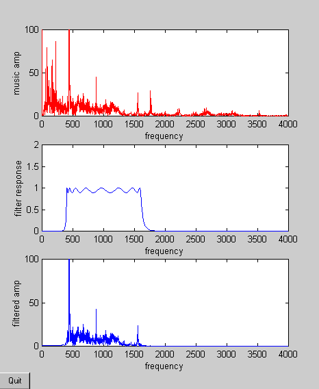
code slightly to change the filter. The program opens one window with three
subplots, shown below. The first subplot is the spectrum of the input signal.
The second subplot shows the chosen filter frequency response. The third subplot
is the spectrum of the input signal after it is filtered. The program is written
as a simple loop which executes until a quit button in the lower left corner
of the window is pressed. The loop repeats as soon as the analog output is
complete.