Digital Signal Processing
DE1-SoC
Cornell ece5760
Audio Digital Signal Processing
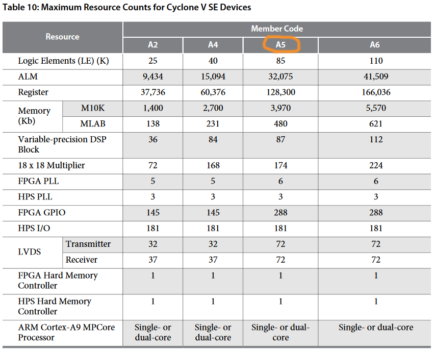
There are 87 DSP blocks on our FPGA. Each one can be used in a number of ways.
-- Audio loop-back configuration
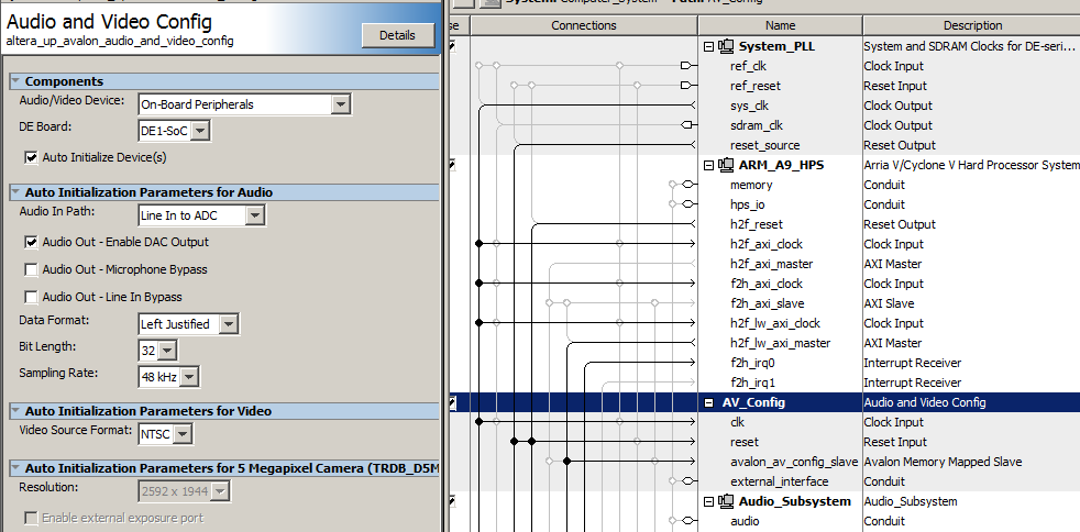
The University Audio Core supports audio input and output at various rates and resolutions, and exposes the data on the Avalon bus. The Bus Master page explains the basic connections. There is a control word, four 8-bit FIFO fields (in/out, left/right), and left/right data registers. The lef/right data registers are read/write. Properly configured, a read to the data register gives data from the audio ADC, while the write to the data register outputs to the audio DAC. The Audio Configuration module needs to be modified in Qsys for proper operation. Double-click the module name in Qsys to open a dialog box. In the dialog box, set up: (1) Audio in Path: Line In to ADC; (2) Check Audio Out-Enable DAC Output; (3) Uncheck Audio Out-Microphone Bypass; (4) Uncheck Audio Out-Line In Bypass
Generate the Qsys design, and recompile the project. This project just loops the audio input to the audio output, except that if you turn switch zero on, a tone is generated on the left channel with a frequency proportional to all the switch settings. You have to press reset (button zero) after you load the design to start the state machine. (top-level module, ZIP of project).
-- A slightly reorgnized design separates the audio waveform generation and connections from the audio interface bus-master state machine. The DDS and loopback connections are separate from the generic bus read/write. (top-level module)
-- Audio Filtering on FPGA
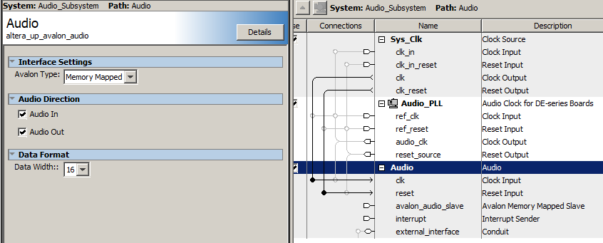
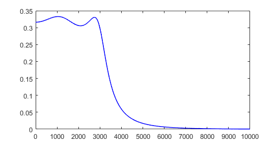
The audio codec settings were changed in Qsys to enable 16-bit, 2's complement signals, to match the filters which had already been written for the DE2. Changing the codec bit-width requires an edit (in Qsys) to both the AV_config dialog box, then open the Audio Subsystem and edit that dialog box. The test filter was a 2-pole Butterworth, bandpass filter at 3000 to 6600 Hz, with a normalized freq 0.125 to 0.275, and Peak at 0.2 which is 4800 Hz. Actual measured peak is 4740 Hz. The matlab code which writes the Verilog filter definition and converts to 2:16 fixed point format is also at the end of the top-level file. (top-level module, ZIP of project). The coefficients for a 2-pole butterworth never exceed +/-2.
-- Audio Filtering with decimated sample rate on FPGA
Low frequency filters can be unstable with limited corfficient bits. A scheme to drop the sample rate to 8KHz (for voice) low pass filters the signal so that frequencies above 4 KHz are attenuated about a factor of ten. Then the sample rate is lowered by taking every 8th sample out of the lowpass filter. This example compares two 300 Hz center frequency, Butterworth filters, with a design bandwidth of about 100 Hz. One is running at a sample rate of 48KHz, the other at 8KHz using input from the decimation filter output. (top_level module, project ZIP). The actual performance of the two seems very similar. Actual center frequency is 300+/-3 HZ. Bandwidths are similar, with half-amplitudes at about 225 Hz and 420 Hz. Filter headers were generated using a matlab script to translate filter coefficients from floating point to 2:16 fixed point. Another script was used to design the decimator filter.
-- Audio synthesis
To convert 32-bit sound to 16-bit sound convert the references to fix2audio28(a) to fix2audio16(a) where
// shift fraction to 32-bit sound
#define fix2audio28(a) (a<<4)
// shift fraction to 16-bit sound
#define fix2audio16(a) (a>>12)
-- Drum: An audio peripherial driver code for the HPS (audio code) was modified to support a finite difference drum scheme. The drum coded is a linear system with coefficients chosen so that cheap fixed-point shifts could be used to generate the 32-bit sound samples at 48Ksamples/sec. At -O3 optimization, I could just fit a 30x30 FDTD drum into the 20.8 microsecond systhesis time frame. If a more general drum tension is simulated with amplitude-dependent tension, then the size drops to about 24x24 grid points. See lab 2 (2018) for references and details. Courant stability puts limits on rho in the code (speed of sound) to 0<rho<0.5. A lower rho means lower natural frequency.
-- String (plucked): The audio code can also support a one-dimension finite difference simulation of a string to generate the 32-bit sound samples at 48Ksamples/sec.. Here the Courant stability limits 0<rho<1.0. The program asks for rho (0 to 1.0, initial amplitude (0 to 0.5), and the width of the pluck (0.5 to 30).
The string fundamental
frequency = Fs*sqrt(rho)/(2*(string_size-2)).
The factor of 2 is there becuase we want to scale with the round-trip distance of the wave on the string. Subtracting 2 from the string size accounts for the zero end points. Square root of rho is proportional to the speed of wave propagation.
-- String (plucked): A variant of the string code plays a scale using 32-bit sound samples at 48Ksamples/sec.. You choose the octave, pluck amplitude and pluck width. Octave zero starts at note C0. Octave four starts at C4. Pluck amplitude should be around 0.25, Pluck width varies from 0.1 to 100. the narrower the width, the more high frequency components are in the note. The initial condition is the product of a triangle wave and Gaussian to ensure that there are no discontinuities at the end points. Example with octave 2, width 10. Example with octave 2 width 1.
-- Improved String Audio Synthesis (using HPS to drive FPGA interface)
The actual string sample update is performed by numerical solution of the wave equation.
Study Notes on Numerical Solutions of the Wave Equation with the Finite Difference Method, equation 2.15 yields the finite difference form to step the solution forward one sample.

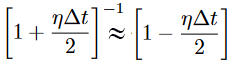
Where un+1 is the displacement at the new time step and i represents the distance along the string. ρ is the propagation speed (range 0 to 1.0 for Courant stability). η is the dissipation which is small (typically 0.001 or so). Because η is small, we can Taylor expand and show that
The code is converted to 16-bit sound, and the Verilog uses SW[9] to turn off the audio bus master to avoid conflict between samples produced by the HPS and audio bus master. Turn SW[9] ON to disable the bus master and allow the HPS exclusive control of the audio subsystem. When SW[9] is off, the bus master can control the audio interface. In this mode, SW[0] and SW[1] control filtering of audio signals fed into the line-input on the DE1-SoC, as described in Audio Filtering with decimated sample rate above.
(Verilog, ZIP of quartus project, address_map_arm_brl4.h, Qsys layout).
-- String (plucked 1D PDE on HPS): A variant of the string code plays a scale using 16-bit sound samples at 48Ksamples/sec.. You choose the octave, pluck amplitude and pluck width. Octave zero starts at note C0. Octave four starts at C4. Pluck amplitude should be around 0.25, Pluck width varies from 0.1 to 100. the narrower the width, the more high frequency components are in the note. The initial condition is the product of a triangle wave and Gaussian to ensure that there are no discontinuities at the end points. Example with octave 2, width 10. Example with octave 2 width 1.
See also Finite Difference Method in Sound Synthesis.
-- String (bowed 1D PDE on HPS): An approximation to bowing uses a periodic drive instead of a initial condition pluck. The approximation I used is an impulse train with settable frequency, often the fundamental of the string (or half the fundamental), and some added noise. A more complete approximation would model the stick/slip of the bow on the string explicitly. An example with octave=2, amp=0.0001, rise time=30000, fall time=5000, detune=1, impulse amp=1, noise amp=0.5. Octave=4 starts at middle C (C4).
A slight variant allows the bow drive function to be wider than a 1 sample impulse. An example input might be:
octave=4, amp=0.0001, rise time=30000, fall time=5000, detune=0.501, impulse amp=1, impulse width=5, noise amp=0.5.
Making the drive pulse wider, and choosing a drive frequency sligthly different than half seems to make a smoother sound.
-- String (bowed 1D with better damping on HPS): A better bowing function, along with full damping support makes a model string which can be plucked (with a fast rise time bow) or bowed. Input parameters are now: damping=(.99-.99999), octave=(1-4), drive amp=(.00001-.001), drive rise time=(1-40000), drive sustain time=(1-40000), drive fall time=(1-40000), drive tune=(0.5-2.0), drive impulse amp=(0-1), dirve impulse width=(1-100), drive noise amp=(0-1). Drive times are in synthesis samples (48000 samples =1 second). Drive rise time is short for pluck, long for bow. Drive tune is relative to string fundamental and works better for values around 0.5, 1.0, 2.0. The drive waveform is currently an impulse+noise at the drive tune frequency, with settalbe impulse width. After the impulse, for the rest of the cycle, is white noise. A table of some input parameters is here. (Code) If you drive the string too hard, it overflows and makes broadband noise.
-- String (bowed and plucked 1D with full damping on HPS): A better combination of plucking and bowing results from adding an initial condtion to represent a pluck and a controlled rise, sustain, fall impulse train to simulate bowing. There are eleven parameters to set: damping eta, frequency octave, bow (overall amp, rise, sustain, fall, tune, impulse amp, width, noise), and pluck amp. Typical values might be 0.9999 2 0.001 1 1 2000 2.00 0 1 .1 0.1. (Code)
-- Drum (linear 2D PDE): A wave equation simulator on the HPS (drum code) supports a finite difference, second order scheme. The drum coded is a linear system with coefficients chosen so that cheap fixed-point shifts could be used to generate the 16-bit sound samples at 48Ksamples/sec. At -O3 optimization, I could just fit a 30x30 FDTD drum into the 20.8 microsecond systhesis time frame. If a more general drum tension is simulated with amplitude-dependent tension, then the size drops to about 24x24 grid points. See lab 2 (2019) for references and details. Courant stability puts limits on rho in the code (speed of sound) to 0<rho<0.5. A lower rho means lower natural frequency.
-- Audio Synthesis on FPGA with control from HPS
Basic wave solver with simple pluck. The 1D wave equation solver with setable initial condition (pluck) was converted to a state-machine running on the FPGA, with HPS communication via shared memory block. The HPS controls the note to be played (frequency, damping, intensity) then reads back the samples to send to the audio interface. The intention is that the HPS is the sequencer which plays the FPGA.
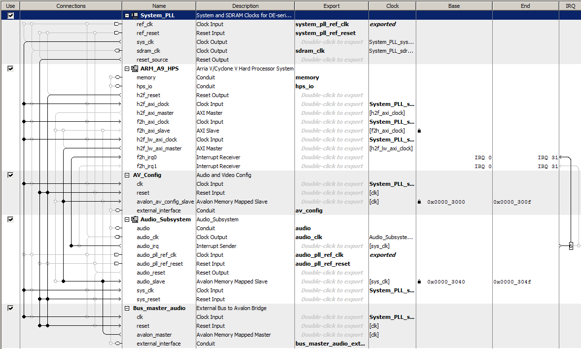
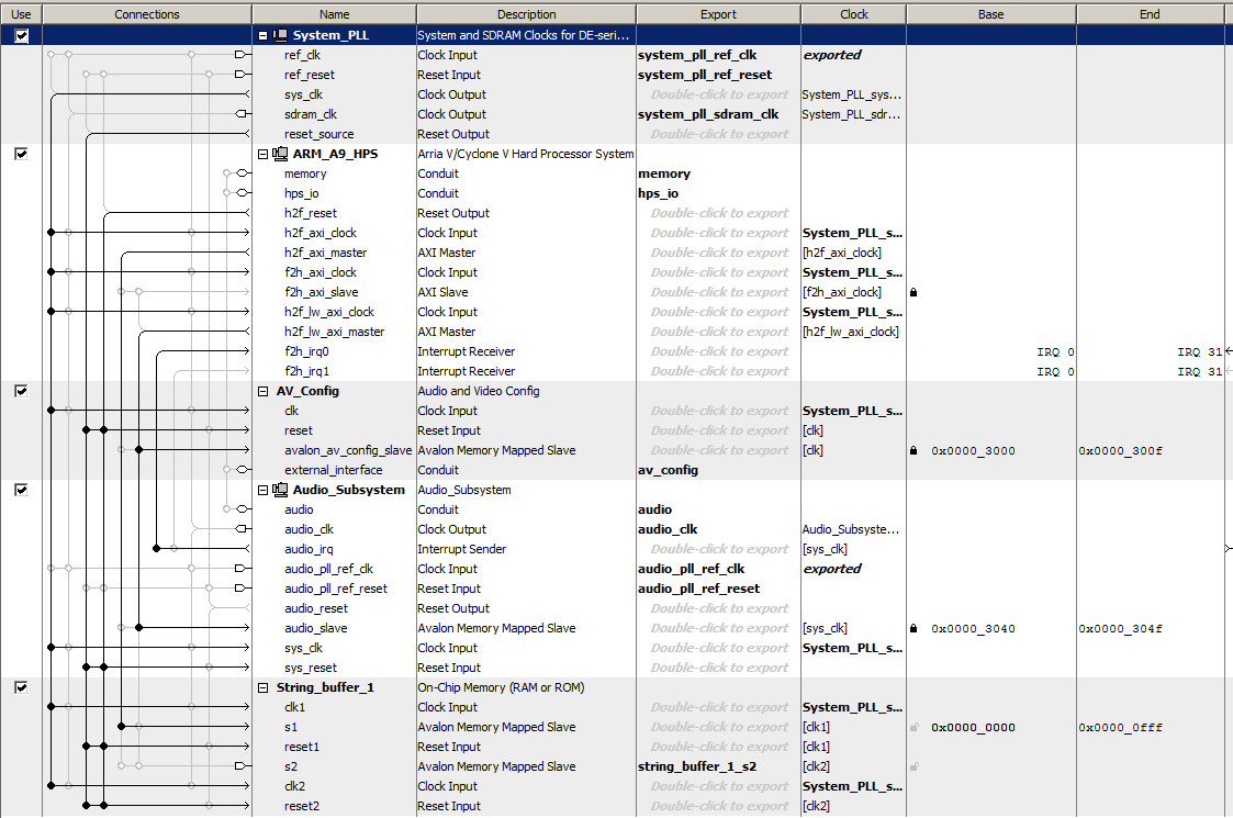
The Qsys layout shows the audio interfaces connected to the h2f_lw_axi_master light-weight bus and the string-control memory block connected to the h2f_axi_master at address 0x0000 to 0x0fff. Both the HPS and the FPGA can read/write the memory block. The memory map is in the table below. All addresses in the table are relative to the base address of the memory block. When the HPS wants to play a new note, it loads string length, rho, and damping, then sets the initial condition for the string array and and zeros the synthesis time counter. The HPS then checks the audio output FIFO to see if a sample is needed, and if so, sets the trigger variable, waits for the trigger variable to be cleared, then copies the string output to the audio interface. The FPGA state-machine waits for the trigger variable to be set, reads the parameters, updates the entire string, then clears the trigger variable, to signal the HPS. One string uses four M10K blocks and three DSP blocks, so about 30 strings can be implemented on the FPGA we are using.
(HPS code, Verilog, Quartus ZIP)
| Address |
Contents |
| 0x000-0x0c7 (0-d199) |
The finite difference elements of the string U(i) |
| 0x0c8 (d200) |
The length of the string (number of elements on the string,
including the ends held at zero) |
| 0x0c9 (d201) |
Rho, the normalized speed of sound on the string. Range 0<rho<=1.0 |
| 0x0ca (d202) |
Damping expressed as (1-eta*dt/2). Typically 0.99 to 0.99999 |
| 0x0ff (d255) |
Trigger. Write 1 to this location to start a new sample. Read a 0 when complete |
| 0x100-0x1c7 (d256-d455) |
The finite difference elements of the previous time step Uold(i) |
| |
|
Approximating a bow and pluck input. A time-dependent input can be generated by the HPS controller code to simulate moving a bow across the string, or other input. On every synthesis cycle the HPS has to do a few operations to evaulate a driving function and send it to the FPGA. The FPGA solver and Qsys remain unchanged. The driving function chosen is a rough approximation of what a physical bow produces, which is a low duty-cycle square wave at some frequency related to the string fundamental. Direct Digital Synthesis was used to generate a drive waveform of the correct frequency, from a square wave table. The drive waveform is shaped by a simple attack-sustain-decay envelope (figure 1.18). The shaped drive waveform is added (for each audio sample) to one node of the string solver running on the FPGA. The HPS demo program plays a scale. A command line input lets you set:
- The octave 1 to 5 (start at C1 to C5 and play 8 notes)
- Damping as a number in the range of 0.99 to 0.999999.
This number is the energy surviving from one sample to the next,
so a damping value of 0.99 makes a sound which is quite short, on the order of 100 cycles.
- pluck_amplitude, typically 0.01 (quiet) to 0.25 (loud).
Setting amplitude too high overflows the solver and makes unpleasant, loud noises!
- bow_amplitude, typically .00001 to .001
Setting amplitude too high overflows the solver and makes unpleasant, loud noises!
- bow rise time, measured in number of samples.
Minimum value is 1, max is determined by the desired effect.
- bow sustain time, measured in number of samples.
Minimum value is 1, max is determined by the desired effect.
- bow fall time, measured in number of samples.
Minimum value is 1, max is determined by the desired effect.
- bow tuning, specified as a ratio of the drive waveform frequency to the fundamental of the string.
Typical value might be 0.5 or 1.0, but could be other ratios.
- bow impulse width, the number of nonzero values in the drive waveform impulse train.
This parameter does not change the sound quality very much,
but making the duty-cycle bigger increases the amplitude of the output.
- pluck/bow position, as a fraction of the length of the string.
Typical value might be 0.05 to 0.95.
Positions near the ends of the strings
emphasize higher harmonics.
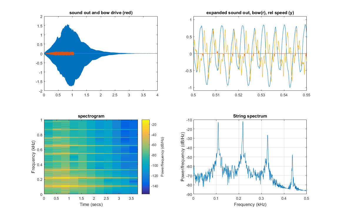
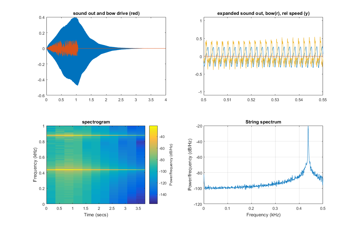
Physical bow model. A better time-dependent input can be generated by the HPS controller code to simulate moving a bow across the string, using a reasonable physical model for the string-bow interaction. The model used is a simplified version of the model in Two-Polarisation Physical Model of Bowed Strings with Nonlinear Contact and Friction Forces, and Application to Gesture-Based Sound Synthesis by Charlotte Desvages and Stefan Bilbao.
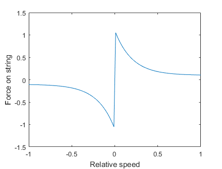
If (dui)/dt is the string velocity at some point on the string, i, and vbow is the bow speed set by the user, then define
Vrel = (dui)/dt - vbow
and the input force added to the PDE solution at point i is
Fbow = Abow * sign(Vrel) * (eps + exp(-abs(Vrel)/v_width))
Where Abow is a drive force, v_width is a speed scale, and eps is a small constant, all set by the user.
(matlab plot)
The input force Fbow*0.5 is assigned to points i-1 and i+1 and Fbow*0.25 is assigned to points i-2 and i+2 to reduce spatial aliasing.
You can control the bow speed, vbow, the applied bow pressure, Abow, and
two parameters related to how sticky the bow is at low speed, v_width, and eps,
which set the level of speed-independent stickyness.
The first step is to get matlab running the algorithm to check for correctness and sensitivity to parameters. The system is sensitive to bow speed parameters and bow amplitude, so it takes some adjustment of parameters to make a good sound. See Playability Evaluation of a Virtual Bowed String Instrument. Also see Playability of the wolf note of bowed string instruments. See The bowed string insruments for time domain instrument response.
(Matlab code, output image, sound(bowed A2))
Multiplying rho by 16 (times 4 in frequency) tunes the string to A4, but the pluck amplitude needed to be dropped to 0.0002 to avoid spurious dispersion on the model string, which sounds like an annoying high-pitched ringing.
(sound(bowed A4), sound(plucked A4), output image)
-- Audio Goal (no verilog yet)
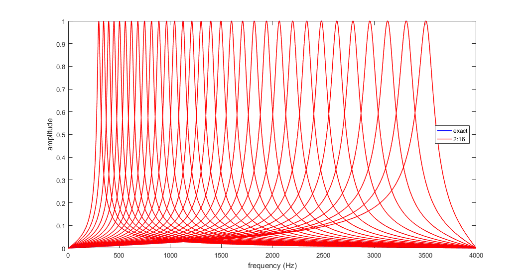
Build speech vocoder based on a mel-spectrum analyser. Output of the mel-spectrum is feed to a envelope filter with a time constant of about 16 mSec, then re-synthesized from sine waves. (matlab code).
HRTF/HRIR
Copyright Cornell University
June 14, 2019
![SW[9] to turn off the audio bus master](../DSP/Audio/Synthesis/Improved_string/disable_bus_master.PNG)