Power Estimation/Measurement
in Quartus Prime
Cornell ece5760
Power Estimation
Power analysis in Quartus Prime is described in Quartus Prime Handbook Vol 3, chapter 9. We will be concerned with the Quartus PowerPlay Power Analyzer, but not the Early Power Estimator. A separate application note discusses Cyclone V SoC Power Optimization.
The dependability of the power analysis depends on the amount of detail that you give the analyser. At the very least, you need to compile, place and fit the design for the specific FPGA model and you need to estimate the time-density of signal transitions. The following example uses the project ZIP GPU with FAST display from SRAM from the bus-master page.
Steps:
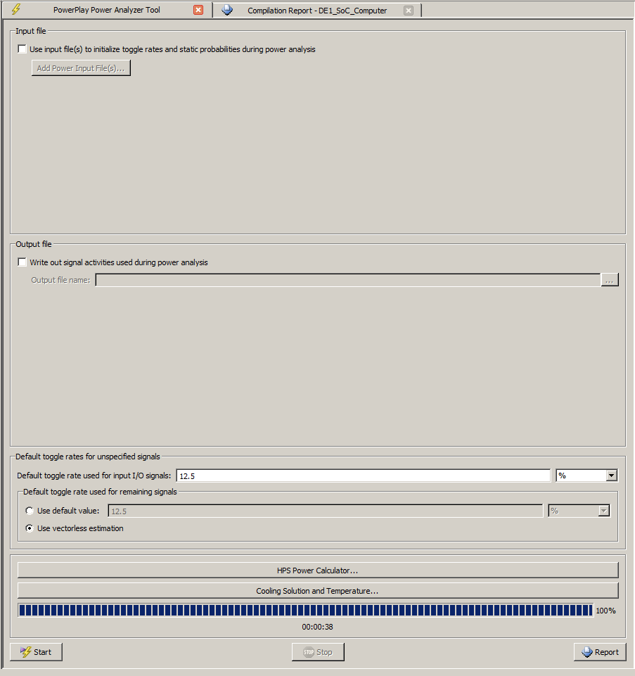
- In the Assignments menu, choose settings...PowerPlay
- In the Processing menu choose PowerPlay tool and set the time-density of signal transitions.
For a quick estimate set Use vectorless estimation. The defaults for the analysis are shown.
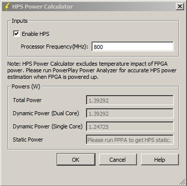
If you are using HPS, then open the HPS tab, enable the HPS, and set the clock frequency.
It appears that 800 MHz is the highest you can set, which seems to match with the Qsys ARM9 dialog box.
Open the Cooling tab and (for DE1-SoC) choose to no heat sink, low air flow.
- Back in the main PowerPlay window, press Start, wait for the analysis to finish, and press Report.
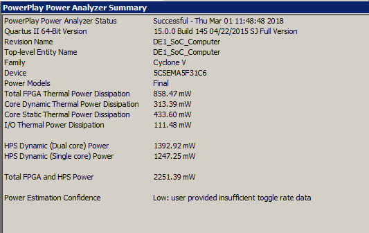
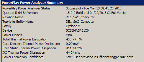
This report is generated by the defaults above.
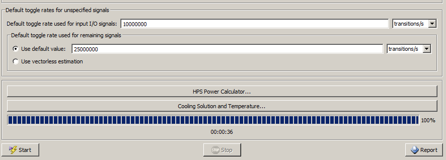
- With the HPS disabled in the HPS dialog, and explicit FPGA toggle frequencies chosen,
the PowerPlay tool generates this report.
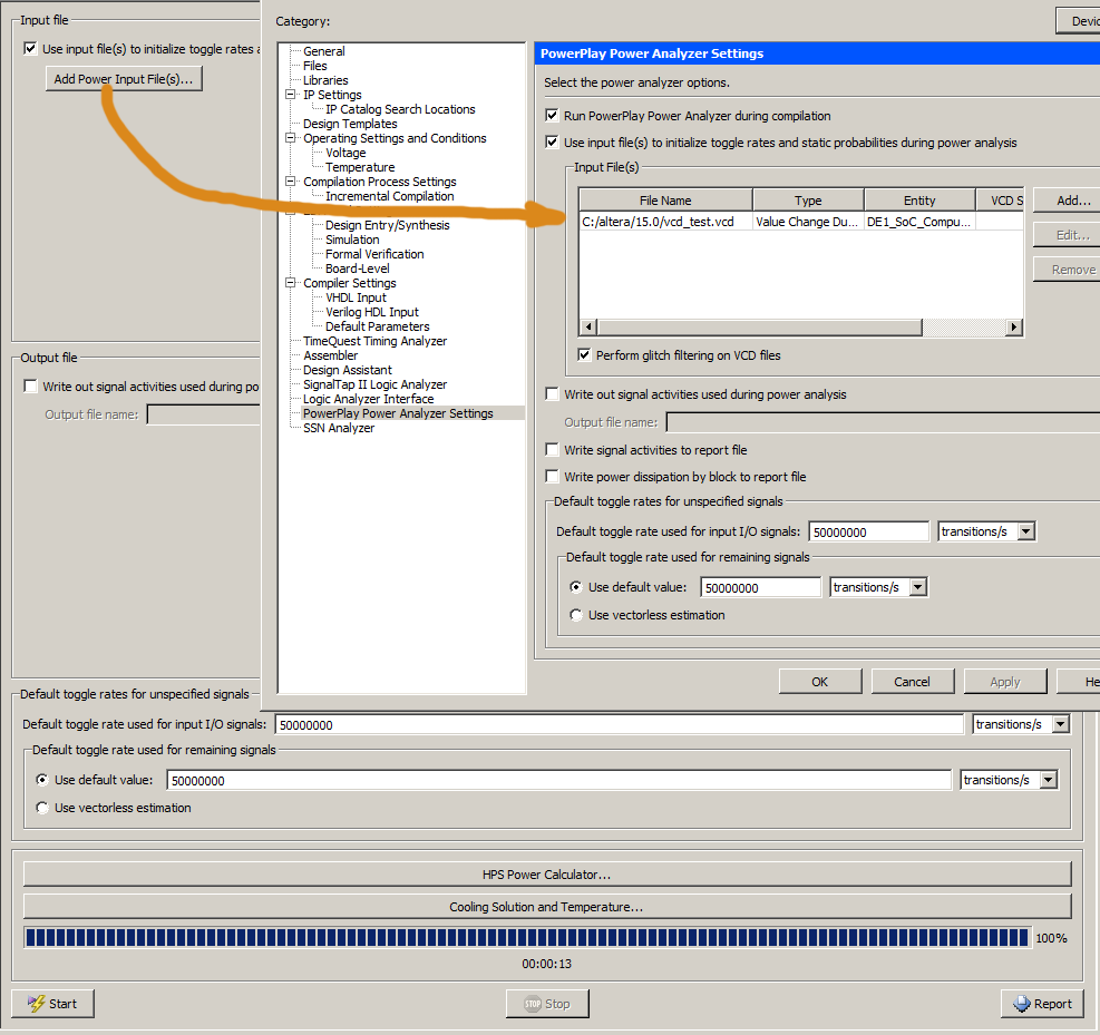
For a more accurate power estimate, you need to supply a Modelsim simulation result. Section 2.2.7 Generating Power Analysis Files in Quartus Prime Handbook Vol 3 shows how to generate a value_change_dump file (vcd file) to feed into the power analysis tool. Further information is in section 9.5.2 Using .vcd for Power Estimation, and particularly section 9.5.2.1.1 Generating a .vcd from ModelSim Software.
Generating an example vcd file in Modelsim:
- Compile using
Compile...Compile All. You should see message # Compile of testbench.v was successful.
(assumes that you are using the example from the Using Modelsim page)
- Chose
Simulate...Start Simulation and in the dialog box navigate to work...testbench.v
- At the Modelsim> command line choose the signals that should be in the vcd file.
To add all the signals from the DDS unit:
vcd add testbench/DUT/*
- Choose
Simulate...Run...Run 100.
- At the Modelsim> command line, type quit -sim (or use the End Simulation menu item) to close the vcd file.
- The resulting data is written into the file dump.vcd, in the project directory.
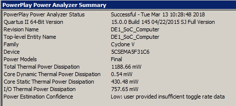
A small example (no HPS, no Qsys) was compiled in Quartus, and also simulated in Modelsim to produce a vcd file.
Using just the default settings for the PowerPlay software (no vcd file, use vectorless estimate) yields a dynamic core power of 0.29 milliwatts, with 44 mW i/o. Using the vcd file, and realistic transition rates (GUI) gives a power of 0.54 milliwatts, with 757 mW i/o.
Power Measurement
The DE1-SoC board does not ship with current measurement capability. The schematic and users manual suggests several ways of measuring power:
- The whole board could be monitored by plugging the power adaptor into a current sensor. The current sensor output would then be applied to the onboard ADC and read by the FPGA. An example might be the Adafruit 1164, using the TI INA169 current sensor. The sensor board has a bandwidth of 100 KHz, gain of of one volt out per amp input, and with an output noise of about 7x10⁻⁵ volts. Because the current is measured for the whole board, separating out the FPGA contribution will require careful calibration, but see below.
- From the Altera Forum. flz47655 writes:
I measured power consumption from 12v AC/DC adapter, here are the results:
fpga configured from EPCS with default demo 0.3A
fpga configured from EPCS with default demo + sd inserted 0.42A
fpga configured from HPS with no SD 0.25A
fpga configured from HPS with SD with Linux Console 0.37A
fpga configured from HPS with SD with Linux Console with ethernet cable connected 0.51A
fpga configured from HPS with SD with Linux Console with ethernet cable connected + cpu1 100% 0.52A
fpga configured from HPS with SD with Linux Console with ethernet cable connected + cpu1 100% + cpu2 100% 0.53A
With fpga only are 12*0.3=3.6W, a lot of power. Someone can confirm this is normal and my board is not wrong? Where go all of this power?
Power consumption seem a lot of independent from cpu load... this seem hard to be right!
Anyway with 12*0.5A=6W an heatsink is indinspensable when using ARM cores!
---and---
component description -- voltage -- current -- power
AD7928 adc -- 3.3 -- 0.0027 -- 0.00891
WM8731 audio codec -- 3.3 -- 0.0002 -- 0.00066
Si5350C-B clock -- 3.3 -- 0.085 -- 0.2805
43TR16256A-85120AL ddr3 sdram -- 1.5 -- current is quite variable 0.08-0.800 -- power 0.1-1.0
EPCS128 flash -- 3.3 -- 0.0003 -- 0.00099
ksz9021rl ethernet -- 3.3 -- 0.045 -- 0.1485
ADXL345 accelerometer -- 3.3 -- 0.00014 -- 0.000462
IS42R16320D fpga sdram -- 3.3 -- 0.05 -- 0.165
FT232R uart to usb -- 3.3 -- 0.015 -- 0.0495
USB2512B -- 3.3 -- 0.05 -- 0.165
USB3300 -- 3.3 -- 0.025 -- 0.0825
ADV7123 video dac -- 3.3 -- 0.08 -- 0.264
ADV7180 video decoder -- 1.5 -- 0.044 -- 0.06
USB Blaster -- 3.3 -- 0.1 -- 0.33
-----------------------------------------------------
Total nonFPGA power = 1.7 watt, but the uncertainty is large at least .5 watt
References:
DE1-SOC literature list
http://wwwhome.cs.utwente.nl/~molenkam/ods/low_power_exercise/dds-power.pdf
https://www.youtube.com/watch?v=F7t4WsuieIE
http://www.eecg.toronto.edu/~vaughn/papers/power_optimization_2005.pdf
http://citeseerx.ist.psu.edu/viewdoc/download?doi=10.1.1.698.4334&rep=rep1&type=pdf
Copyright Cornell University
March 14, 2018