Design
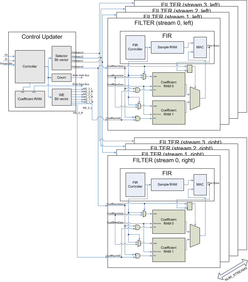
The following diagram shows the organization of our filter setup for multiple audio streams. Note the inputs of this system are the input azimuth, elevation, and a stream selector, sent from the GUI through the UART. The output of this system is the audio sent to the user.
Also note that there are two FILTER blocks (which interally are identical). The top FILTER block is for the left channel of the audio stream (and its filter will perform the HRTF for the left ear), while the bottom FILTER block is for the right channel of the audio stream. The lines labeled Filter Select, Write Addr and Coeff Data attach to the inputs to both FILTER blocks (not shown in the diagram to reduce clutter). The write enable lines (WE_L and WE_R) are the only different between the FILTER blocks.
We will discuss each of these in detail in the following sections, and put it all together as we go.
Note that in order to minimize complexity in debugging and developing our code, we did all of our FPGA logic in hardware and opted not to use a NIOS II processor.
FIR
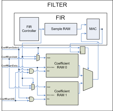
The FIR module (implemented in fir.v) is a multicycle 200-tap FIR filter. A functional diagram of the FIR filter is provided.
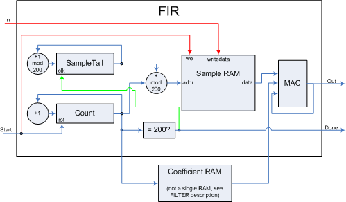
The inputs and outputs of the module are:
| Name | I/O | Description |
| Start | I | One-cycle pulse indicating when the filter should latch In |
| In [15:0] | I | Input sample to filter |
| Done | O | 200 cycles after Start is asserted, Done will pulse for one cycle indicating that Out is the output of the filter |
| Out [15:0] | O | Output of filter |
| CoeffRAM_Data | I | Coefficient needed to perform calculation |
| CoeffRAM_Addr | O | Address of coefficient needed to perform calculation |
| Name | I/O | Description |
| CoeffRamAddr | I | Coefficient address to write new coefficients, and read coefficients for FIR operations |
| CoeffRamData | I | Coefficient data to write |
| CoeffRamWE | I | Are we writing coefficients to the writable coefficient RAM? |
| CoeffRamSelect | I | Which RAM is writable. Also ~CoeffRamSelect is which RAM is being read by the FIR |
| Name | I/O | Description |
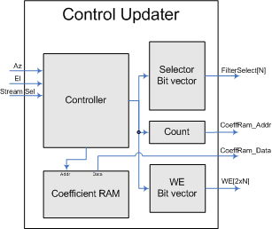
| Azimuth | I | New azimuth for the specified stream |
| Elevation | I | New elevation for the specified stream |
| Stream Sel | I | Which stream we are updating |
| Start | I | Pulse indicating a new azimuth & elevation are available |
| ExSRAMAddr | O | External SRAM read address |
| ExSRAMData | I | External SRAM data port |
| CoeffRam_Addr | O | Coefficient address to write to FILTER module |
| CoeffRam_Data | O | Coefficient data to write to FILTER module |
| FilterSelect N vector | O | Select line for each FILTER module (0 = coeff RAM 0, 1 = coeff RAM 1) |
| WE 2xN vector | O | WE lines to each FILTER module controlling the writable coefficient RAM |
| Command | Value | Payload & Description |
| Fill SRAM | 0x0000 | 250,000 2-byte coefficients, in the order specified in the Coefficients section of this report. |
| Change az/el | 0x0001 | The first 16-bit word of payload is a combination of stream number (in the high-byte) and azimuth (in the low-byte). The second 16-bit word is the elevation. Note that azimuths and elevations are specified as an integer between 0 and 24 inclusive. |
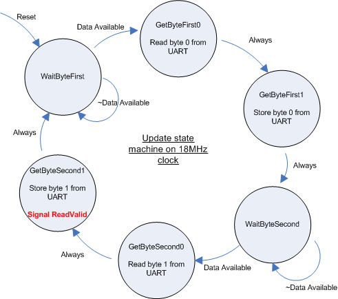
The commanding code is implemented in DE2_TOP.v and impements the following state machine:
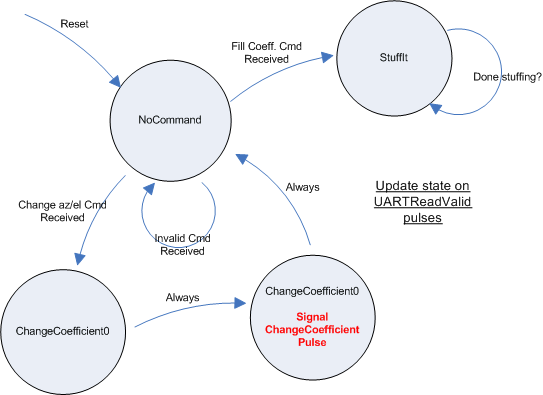
Here we begin in NoCommand until we receive a valid command (0x0000 or 0x0001). If we receive 0x0000 we move into the StuffIt state, where we load 250,000 coefficients into the external SRAM. We loop in this state until we have loaded all the coefficients, and then return to NoCommand. Running at 115kbps, this takes approximately one minute to complete.
If we receive 0x0001 we move into ChangeCoefficient0 where we load the azimuth, then into ChangeCoefficient1 where we load the elevation. Upon leaving ChangeCoefficient1 we signal ChangeCoefficientPulse which triggers the control logic, changing the coefficients in the RAM as described in the control updater section of this report.
Ethernet & Multiple Streams
DE2 Hardware
We use the audio line in for stream 0 (left & right channels of stereo sound). For more audio streams, we transfer packets from a PC to our system over ethernet (100Mbit). Using the DM9000A datasheet, we wrote a hardware driver for the chip such that we could receive raw ethernet frames.
The DM9000A interface is suprisingly complicated. It contains 50+ registers which can be manipulated by using the following sequence:
-
- Set ENET_DATA to the address of the register we wish to write to
- Set ENET_CMD to 0, indicating ENET_DATA contains an address of a register
- Set ENET_WE_N to 0, indicating that we are issuing a write to the chip
-
- Set ENET_DATA to the data we are writing
- Set ENET_CMD to 1, indicating ENET_DATA contains data
- Set ENET_WE_N to 0 if we are writing to the register
- Set ENET_RE_N to 0 if we are reading from the register
This looks simple, but there are restrictions to the above. You must wait for some time between steps 1 and 2. The wait time is at least 1 cycle, but can be 2 cycles, 4 cycles or even 10us if we are reading/writing from/to certain registers. See pages 46-47 for the necessary timing.
To keep things simple in our ethernet driver, whenever we are writing to DM9000A registers, we wait 300 cycles between writes (more than 10us worth). And, whenever we are reading DM9000A registers, we wait 4 cycles (the max number of waits any read can have).
Further, there are setup and hold time restrictions for the ENET_DATA and ENET_CMD lines. We have a setup time of one full cycle, and a hold time of two full cycles (running at 18MHz) to prevent errors in communicating with the DM9000A. Any less and we were not able to write to the chip.
We implement the above steps using a state machine (which we call the RawEthernet state machine) in Enet_IF.v. The state machine is given as follows:
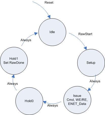
We begin in the idle state. When some part of our system wishes to communicate with the DM9000A, they:
- Set RawRW to 0 if you are performing a register read, 1 if you are performing a register write
- Set RawAD to 0 if you are issuing an address to the DM9000A, 1 if you are writing data to the DM9000A
- Set RawWriteData to the data to be written (either data or an address)
- Pulse RawStart for one cycle.
When the Raw state machine sees a RawStart pulse, it enters the Setup state, where it puts ENET_DATA and ENET_CMD on the bus. In the Issue state, it drops ENET_WE_N or ENET_RE_N low (according to RawRW). Then we raise the enable lines but keep ENET_DATA and ENET_CMD on the bus for two more cycles of hold time.
So for example, if we wanted to write the data 0x3F to the register 0xFE (which clears interrupt flags), we perform the following operations:
-
- Set RawRW to 1
- Set RawAD to 0
- Set RawWriteData to 0xFE (the address)
- Pulse RawStart
-
- Wait until RawDone is asserted
-
- Set RawRW to 1
- Set RawAD to 1
- Set RawWriteData to 0x3F (the data)
- Pulse RawStart
-
- Wait until RawDone is asserted
The chip must be initialized using a certain procedure:
- Write 0x00 to register 0x1F to power up the chip
- Write 0x01 to register 0x00 to reset the chip
- Write 0x00 to register 0x00 to reset the chip reset flag, 10us after the previous step
- Write 0x81 to register 0xFF to reset the interrupt flags
- Write 0x3F to register 0xFE to reset the status flags
- Write 0x2C to register 0x01 to clear status bits
- Write 0x03 to register 0x05 to enable receiving & promiscuous
We perform this procedure through an initialization ROM, for which each 16-bit entry contains the RW and AD bits, and the 8-bits of data to write. The state machine initialization is given as follows:
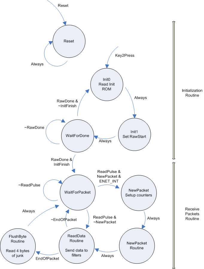
The top half of the state machine contains our initialization state. We remain in the Reset state until Key2 is pressed. Key2 sends the state machine to Init0, where we begin reading the ROM. The ROM data is interpreted in Init1, where we set RawStart high for one cycle, and one initialization command is underway. We enter the WaitForDone state and remain there until the command has been executed successfully. If there are more commands to process (checked by a static value) we go back to state Init0. If we are done with initialization we enter the WaitForPacket, where we wait for audio packets to be sent to our system.
When we are in WaitForPacket, we wait until we should read an audio sample (signalled by ReadPulse) and then process that audio sample. If we are reading a new packet, we must strip & process the header off the next packet (explained later). If we are in the middle of reading a packet we just read the next data frame.
We used the audio_in_ready signal from the audio DAC in order to sample data from the DM9000A at 48kHz.
There is also an interrupt line (called ENET_INT) that we have configured to go high when a packet is received. We use this signal to start reading data from the ethernet port for the first packet only. After this, we rely on the buffer being kept filled with useful sample data. Therefore, we ignore audio_in_ready until the very first packet is received, and from then on we use the audio_in_ready signal to sample the DM9000A.
The PC sends the DE2 board raw ethernet frames. For example, in our tests, we used the following C# code to send 480 bytes of data to the DE2 board:
            byte[] packet = new byte[480];
            for (int i = 0; i < 480; i++) {
                packet[i] = (byte)i;
            }
            rawether.DoWrite(packet);  // write packet
However, when we read the data (2-byte words at a time, little-endian) from the DM9000A (done by reading the DM9000A's 0xF2 register), we get the following data from the DM9000A:
| Read # | Bytes Read | Description |
| 1 | 0x01 0x04 | 0x01 => Status byte indicating that the packet is received 0x04 => Status byte indicating that the packet is a broadcast packet |
| 2 | 0x01 0xE4 | 0x01E4 => Total packet size (480 bytes plus 4 bytes of junk added to the end) |
| 3 | 0x00 0x01 | Our data |
| 4 | 0x02 0x03 | Our data |
| 5 | 0x04 0x05 | Our data |
| etc ... | ||
| 241 | 0xDC 0xDD | Our data |
| 242 | 0xDE 0xDF | Our data |
| 243 | junk junk | Checksum bytes |
| 244 | junk junk | Checksum bytes |
So, at the start of every packet we must strip off the first word read (the two-bytes of status), and we process the second word read (the length of the packet) to know how many bytes to read from the packet. We also need to throw away the last four bytes we read (checksum).
Further, in order for reads to work, before reading the first status word we must perform a read from 0xF0. This read apparently pre-loads the word for a read from 0xF2. So, the procedure at the beginning of each packet is then:
- Read from 0xF0 (necessary to pre-load the receive register)
- Read from 0xF2 to strip the first header word
- Read from 0xF2 to strip the second header word
- Read from 0xF2 to get the first byte of data in this packet
And, if we are in the middle of processing a packet, we just issue a read to 0xF2 to get the next byte of data in the packet.
If we are at the end of a packet we need to read 4 bytes of checksum. The procedure at the end of each packet is then:
- Read from 0xF2 to eat the first word of junk
- Read from 0xF2 to eat the first word of junk
This is all shown in the bottom half of the above state machine, and is implemented in Eth_IF.v
Host PC
Sending raw ethernet packets from a PC running Windows is not trivial as Windows drivers provide high-level socket interfaces for UDP and TCP (not usually raw ethernet packets). We found a neat C++ driver package and accompanying C# interfacing code to use raw ethernet.
The driver we use is available here, along with installation instructions and C# interfacing code. This lets you write raw ethernet frames to our DE2 interfacing code.
Data Flow
We tried to keep data flow as simple as possible. Basically, the PC will transfer data to the DE2 at 48kHz, and the DE2 will read data from the DM9000A at 48kHz. To make this work, we need to:
- Ensure that our Verilog code reads data from the DM9000A at 48kHz. This is done by performing ethernet reads when the audio ADC reads in samples. We know that the audio codec operates at precisely 48kHz, and so we can perform our ethernet reads when the audio DAC performs conversions.
- Ensure that our C# code sends 16-bit samples to the DE2 at 48kHz. This is done through a timer mechanism in C#. The code needs to send 48000 samples every second, and we do this by sending 480 samples every 10ms.
We take a stereo mp3 audio track, use freely available software on the web to convert the mp3's to 16-bit, 48kHz mono audio samples. We then use the C# ethernet driver to send 13 packets (each paket=960bytes) every 20ms using an OS timer. This ensures that the buffer in the DM9000A always remains full, and always has audio samples ready to filter.
The wav file format is very simple. There are 44 bytes of header, followed by raw data. Since our wav file is mono, 16-bit, after 44 bytes of header we read 16-bit words as samples.
GUI
Our GUI contains three components, as shown in the picture below.
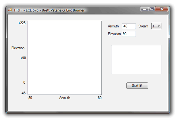
The first component is the 2-D input panel of Elevation and Azimuth. As the user clicks and holds the left-mouse button and drags the cursor around the plot, the sound source moves. In the picture, the user has clicked the mouse such that the azimuth/elevation are -40/90 degrees. The second component is the stream selector. In the picture, the user is setting the azimuth and elevation for stream 1, such that the HRTF coefficient RAMs are only updated for the specified stream.
The third component to the GUI is the 'StuffIt' button which sends all 250,000 coefficients to the DE2 board over a serial port.
