Hardware Design
BALL-EVideo and Display Code
Video Camera Decoding
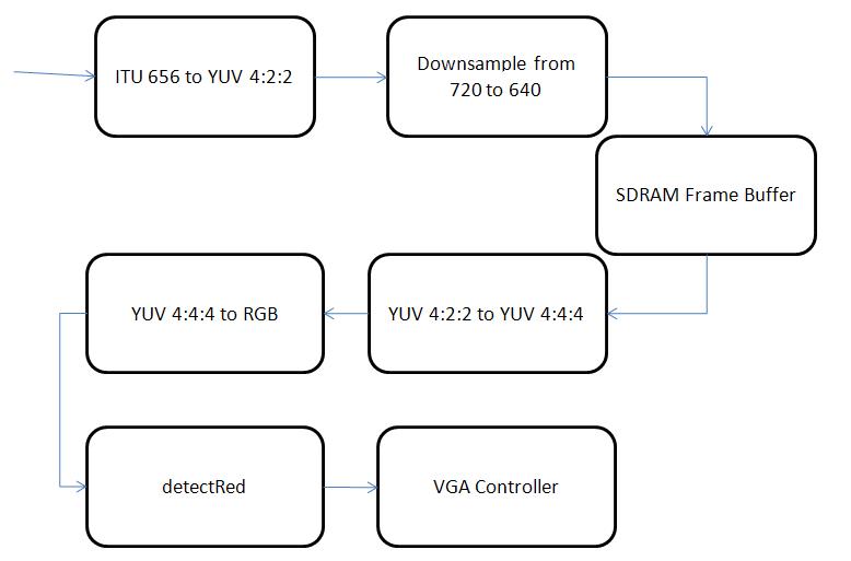
We used a Sony Handycam with a standard NTSC video output as our video camera input. The data is read in from the Video-In plug on the DE2 board and goes through a set of hardware modules that convert the input data to a standard RGB format for display on a VGA monitor. The data that is read in directly from the camera is in the ITU656 format, and must first be converted to a more standard YUV 4:2:2 format, more commonly referred to as YCbCr. The YCbCr format is a color display format in which the different components are Y, Cb, and Cr, which represent the luma component, blue-difference and red-difference chroma components respectively. This format is not an actual color space of its own, but a way of encrypting RGB data. As the data input is converted to this format, the system simultaneously down-samples the signal from 720 to 640 horizontal pixels. After being converted, the data is then fed into an SDRAM FIFO which acts as a frame buffer. The output of the FIFO is then taken through another conversion process, transforming the data from the YUV 4:2:2 format to the YUV 4:4:4 format. Finally, the new YCbCr formatted data is converted once more to the standard 10-bit RGB format. All of the modules which do these various data conversions were provided for us through the DE2_TV example code that comes with the DE2 board provided by Terasic. In the standard example, the RGB data is fed directly into a VGA controller so as to be displayed on a standard VGA monitor. For our purposes, however, we wanted to actually examine the image that is to be displayed, and this is the place in the data flow where we were able to read the data in a format we are familiar with. As such, instead of going directly to the VGA controller, the RGB data goes through one more module, detectRed, which scans the data as it passes through pixel by pixel and highlights those that are red. The image below shows the flow diagram of the video decoder hardware:
detectRed.v
The red detection algorithm works by examining each pixel as it passes through the module and determines whether it is orange or not. If the pixel is determined to be red, it is highlighted in red, and the coordinates of the bounding box are updated so as to include this pixel if it does not already. If the pixel is determined to not be red, then there are a few cases which can occur. The first case if not red is whether the current pixel lies on the border of our bounding box. We keep track of the current and previous three bounding boxes, and if the current pixel lies on any of these, the pixel is displayed as green, blue, cyan, and purple respectively. If the current pixel is not on any of the bounding boxes, but within the area of the current bounding box, the pixel is displayed in its original color. Finally, the default and most common case is that the pixel is converted to grayscale. This occurs for any pixels that are completely outside the area of the bounding box. Determining whether the current pixel is red or not is based on the distance formula with a threshold given to determine whether the pixel color is close enough to a constant reference color. Every pixel has a red, green, and blue component associated with it, and these values can essentially be treated as coordinates on a three valued vector. These values were compared to a constant value found to be very close to the color of the ball we were trying to follow. Typically, the distance between two different vectors is computed by finding the square root of the sum of the squares of the differences between the coordinates of the two vectors in the same direction. However, finding the square root of a value is a hard and resource costly function, so we decided to avoid this step and just compare the sum of the squares to a predetermined threshold value. If the value determined to be the distance between the current pixels color and the reference color was below the threshold, the pixel is considered red and is highlighted. Otherwise it is not considered part of the object we want to find and sent to the other cases mentioned earlier. Every time a pixel is determined to be red, we then determine whether its position is within the area of the current bounding box. If not, then the relevant coordinate of the bounding box is updated so that it will now include the present pixel. This causes the bounding box to essentially be grown outwards from the first red pixel it sees until it surrounds every red pixel. After all the color checking, there is a conditional case that occurs once per frame and essentially shifts the bounding box coordinates into the new current coordinates, as well as shifting the current into the previous, and so forth, with the most previous being shifted out. This module outputs the coordinates of the four bounding boxes, which are then used to determine the input to the control scheme. We also keep track of and output the area being tracked by counting the pixels inside of the bounding box. Finally, the module also outputs the modified color value of the current pixel which is then fed into the VGA controller to be displayed on a monitor.
Robot Control
The purpose of the red detection and bounding box is to act as an input to a controller that dictates the motion of the robot. The original idea was to do some simple motion detection based on the coordinates of the current and previous bounding boxes to determine how to move the robot, but in the end we used only the x-center of the current bounding box. This value is determined by finding the difference between the left and right x-coordinates of the bounding box, halving it by shifting down one bit, and then adding this value back to the left x-coordinate. This value then becomes the input to our neural net, which is used as the basis of our control scheme.
neuralNet.v
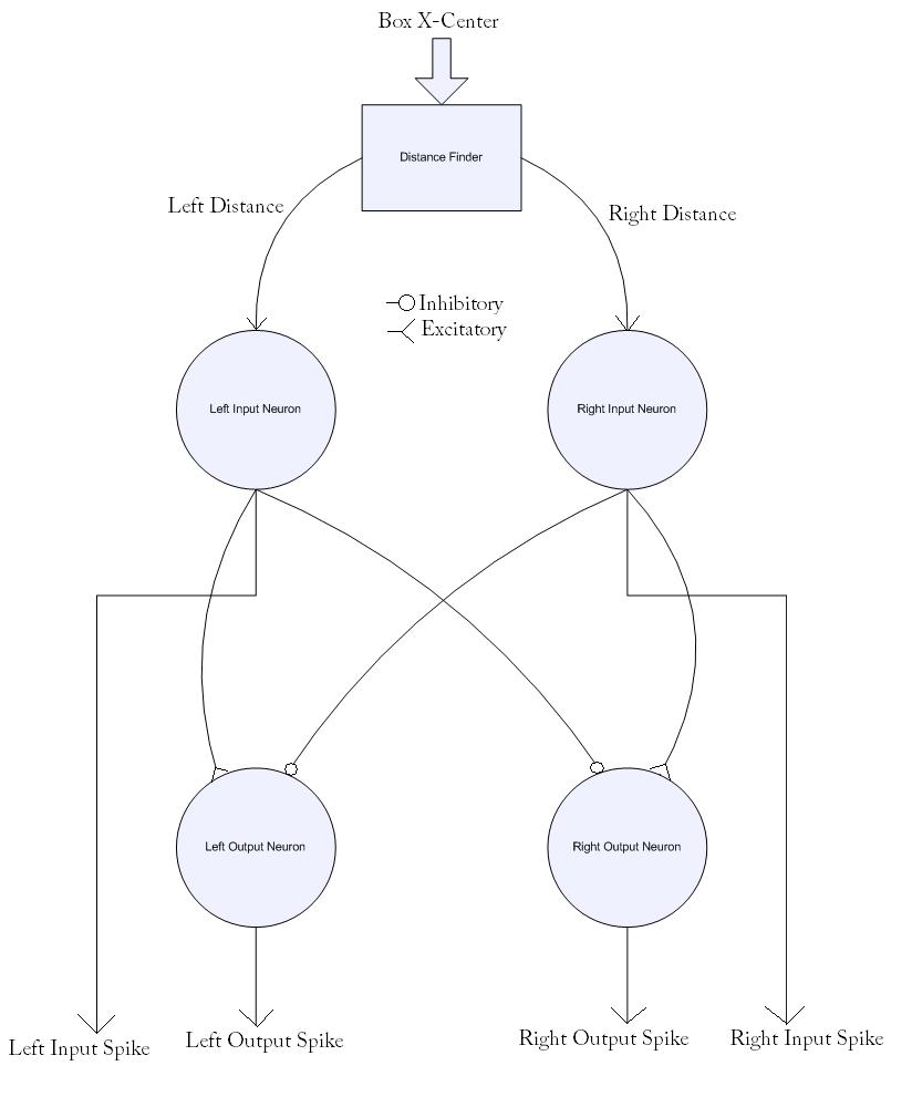
A neural net is a collection of neurons connected together through synapses, meant to simulate the way in which the human brain works. While this is a concept that can very quickly become complex, it is possible to use small neural nets as simple controllers. The net is created by connecting the various neurons together in different arrangements with varying weights on how much each neuron affects the next. A positive weight between two neurons is generally referred to as an excitatory synapse, whereas a negative weight is called inhibitory. Excitatory connections can be used to have the output one neuron greatly increase the chances the next one will react, whereas an inhibitory connection has the opposite effect. There are different models of how neurons should work, and we created spiking neurons based on the Izhikevich Neural Model. We based our code off the example provided by Professor Bruce Land. Our code creates four Chattering neurons, two for input and two for output. There is one left input neuron, one right input neuron, one left output neuron, and one right output neuron. The left input neuron is connected to the left output neuron through an excitatory synapse, while also being connected to the right output neuron through an inhibitory synapse. The right input neuron is connected in the same but opposite way. The input neurons take the left and right distance between the input x-coordinate input and the center of the screen as their inputs respectively. These inputs cause the neurons to spike at a frequency based on how strong the input is, and these spike are then transmitted to the output neurons through the synapses. The excitatory and inhibitory synapse outputs are added together and used as inputs to the output neurons, which then spike accordingly. The diagram below shows the structure of our neural net:
motorControl.v
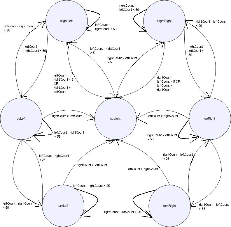
The motor control module takes the output neuron spikes as inputs and monitors them through a stacked set of two counters. The first set of counters is simple and essentially counts the number of spikes on the left and right separately over 100 neuron clock cycles. Then, every hundred cycles, another set of counters increments based on which of the two spike counts is larger (both are incremented if they are equal). These counters go for 64 of their cycles, and then the state machine controlling the output control register is checked. This structure evolved over time after after other methods revealed that the spike counts were too small over the given time window to be significantly different. The state machine has seven different states corresponding to the different motions we want the robot to take turnLeft, goLeft, slightLeft, straight, slightRight, goRight, turnRight. The diagram below shows the structure of the state machine:
Motor Controller
The motor controller consists of the control unit, which had a 3 bit control input, 2 motor enables, and 2 threshold values. These
control bits varied from 0 to 6. Figure 4 shows the control logic for the motor controller.
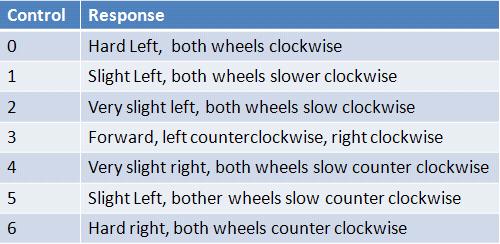
This control logic was implemented in a module, controlmotor.v, using a simple case statement and assignments of enables and thereshold values.
PWM
In order to control the speed and direction (Clockwise or Counter Clockwise) of the motors we had to build a pulse width modulator (PWM). A PWM is used to control the amount of electric power the motor recieves and therefore controls the speed and direction of the motor. A digital PWM is simply a counter that resets after a certain amount of time. A value, called the threshold, is a variable input to the PWM module. For every clock tick that the counter is below the value, the PWM outputs a 0. For ever clock tick that the counter is above the threshold value, the PWM outputs a 1. Varying the threshold value changes the pulsing of the PWM and we discovered that certain threshold values controlled the motor speeds and direction. Figure 5 shows the values we used to abtain certain desired functionality.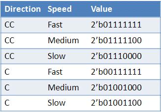
Motors
The motors are connected to an optoisolator to prevent backcurrent spikes from damaging the board. In addition, more circuitry was added
to create a more stable single from the PWM. The schematic for the motor controller can be seen in Figure 6 below.
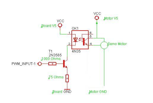
The diode was connected to the 5 volt supply of the DE2 board, and the PWM signal from the GPIO pins on the DE2 Board were fed through stabalization circuitry. The first resistor of 1000 ohms into the base was choosen. Additionally, we decided on the value for the 75 ohm resistor bases on the voltages of the base and emitter on the 2N3964 BJT NPN transistor. The 4N35 diode-BJT optoisolator provides protection for the board from the inductive spikes that the motor puts out when turned off. The motors are Pparallax servos, and thus capable of going both clockwise and counterclockwise based on the input from the diode, which was dependent on the output of the PWM (to be explained later). A seperate 4-6 volt supply was used for the motors, with their own ground. It was imperative that the two grounds and voltage supplies be seperated, and thuse two seperate supplies were used. The board supplied the 5 volts for diode and associated BJT circuitry. We originally used an external 5 volt supply, and the power chord for the DE2 board, but later moved onto batter power. It is necessary that the board either be powered completely by battery power or by external supply. Additionally, if BALL-E was powered by external power, the USB connection to the computer also served as a ground reference, and needed to be connected.
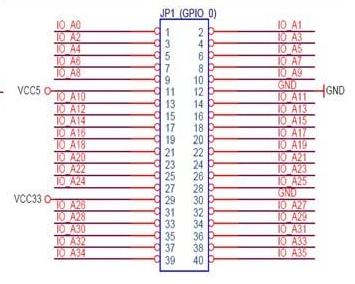
To control the motors, we used the GPIO_0 pins on the Altera DE2 Board. The schematic(shown in Figure 7), shows that there are gnd and 5 volt references built into the pins. We used GPIO_0 1,GPIO_0 5,GPIO_0 21, and GPIO_0 25 pins to control each motor individually.