Introduction top
The final project of our group is the Fruit Ninja Game. This project is primarily based on the HTC 231x CCD camera and a VGA monitor. To player the game, the player mainly needs to move his or her hand, which a cursor will be followed to show that hand is properly tracked, and cut the fruits such as apple and orange to gain scores. If the player hit the bomb by mistake or missed too many fruits, game will be over. The camera will capture player’s motion and send information to FPAG for analysis. The Altera DE2 FPAG will handle all required algorithms to perform necessary calculation to display proper message on the VGA screen. The hand tracking is based on skin colour detection and averages every 8 clock cycles to achieve more stable output. All gaming images are also stored in customized M4K blocks. In addition, we have also added different sound effects when player cuts fruit and bomb. More detailed hardware setup is shown in the RTL level block diagram below.
To implement all required functionalities, we applied all knowledge about DE2 FPGA learned in this semester and also learned camera hardware setup for FPGA and how hand tracking works. We learned hand tracking schemes from previous year designs of ECE 5760 and are properly cited in the reference section. The final goal of this project is to allow the image capture by camera, hand tracking, and the game state machine to run spontaneously. Thus, even though NIOS II based video design can be much easier, we decided to implement everything on hardware purely. The biggest bottle neck comes from the limited resource of hardware due to extensive functionalities required for this project. And our primary works for this final project is to allow all blocks needed for this game to run in parallel, ensure the correct timing and make it synthesisable.
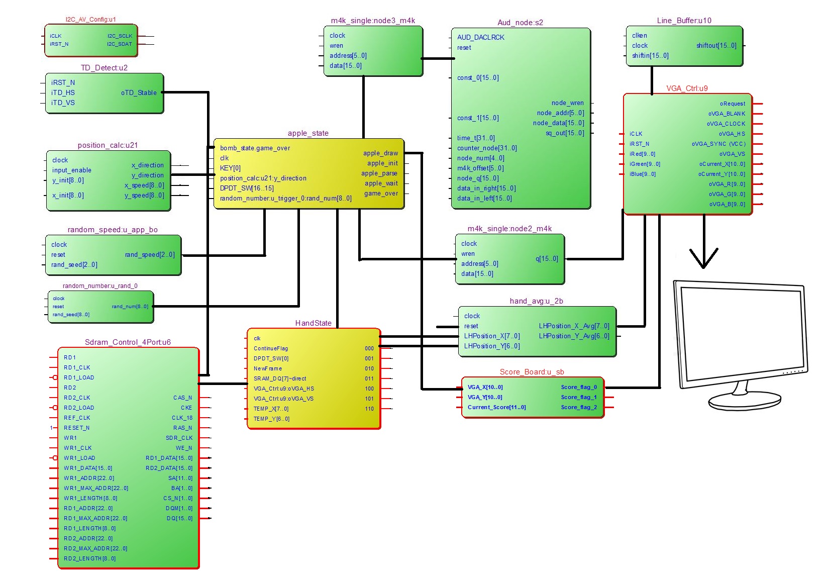
Figure 1. RTL block combined with high level block diagram
FPGA Hardware Design top
The implementation for this lab is entirely dependent to the hardware. We first learned from Altera DE2_TV example to get familiar with the connection between camera and FPGA. Then we moved onto learning all possible methods of hand tracking and decided to use colour detection scheme. The RTL block diagram in previous section also helps explaining the connections between all functions or modules that necessary for this gaming project design. The hardware setup basically involves audio setup and video and camera setup. We display our image primarily by pre-defined M4K blocks and there are a lot of parallel computations required such has hand position calculation, fruit display calculation, random number related functions to simulate non-periodic fruit generation and flying-path, and gaming state machine to determine the current process of the game. And, the following sections will explain that information in details.
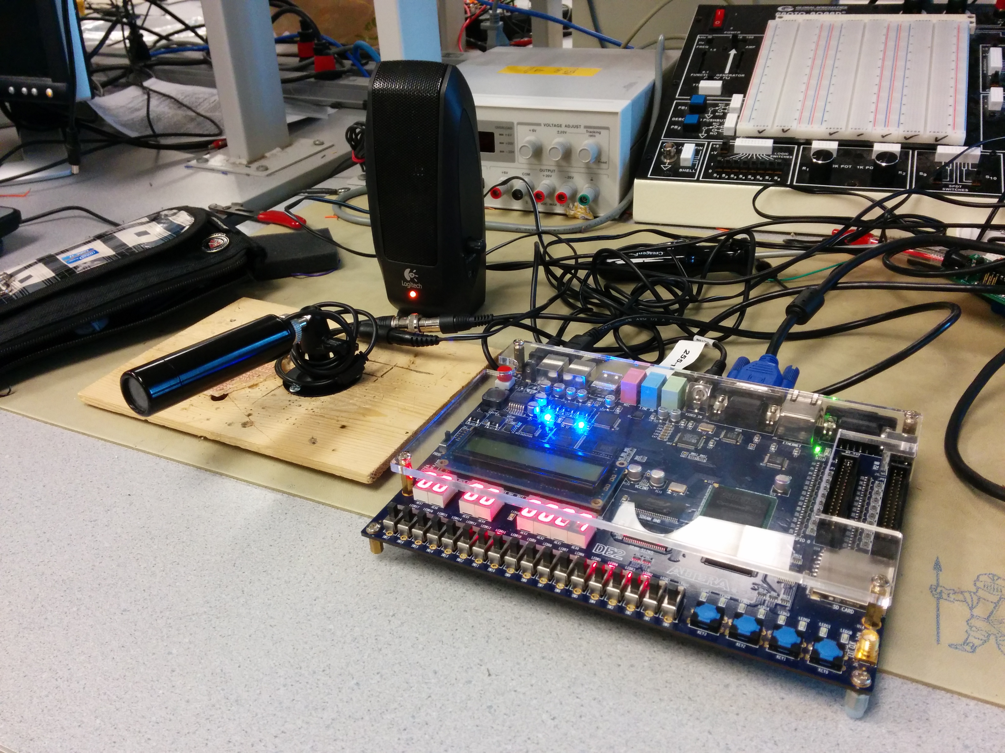
Figure 2. Overall Hardware Setup
Audio Setup
The hardware audio interface used in this lab is Wolfson WM8731. This audio codec is stereo with integrated headphone driver. The digital audio input supports from 16 to 32 bits and the sampling rates from 8 kHz and 96 kHz are supported. In this lab, we use 16 bit input and 44 kHz sampling rate that ensure the input can be successfully taken by the audio codec. The audio block is AUDIO_DAC_ADC with necessary data, clock rest, input and output pins. The most important output pins are oAUD_inL, oAUD_inR, which corresponds to the left and right channel for the audio codec. And these output ports are wired to the output from our own developed drum simulation module. And our simulation module will output only the center point of the drum. Detailed connections can be illustrated as: .oAUD_inL(audio_inL), .oAUD_inR(audio_inR), assign audio_outR = sq_out_s0;assign audio_outL = sq_out_s0; .sq_out (sq_out_s0),. Then, the AUX output port of the FPGA can generate sound properly.
Video and Camera Setup
We used standard VGA_Ctrl module provided by Altera for display purpose. In this module, parameters are defined by host side, VGA side and control side. The host side take input from FPGA and output to VGA side. The oCoord_X and oCoord_Y define a pixel regarding the X/Y axis position. It has I/O for RGB as colour display but is not used in this lab. H_SYNC will start a new line and V_SYNC will start a new page. Several always@(posedge iCLK) blocks are used to correlate input wires with output registers. For example, the sync output is based on incrementing a counter in the always statement. Clock and reset are also implemented for synchronization and control purpose. Moreover, the version history of this VGA controller Verilog file can also be found on ECE 5760 website.
To use the VGA controller properly, we will also need memory to buffer the data and from the DE2_TV example, we learned to use the SDRAM as part of output buffer. That is because different from a pure VGA display that we accomplished previously in this semester, we have also added more camera related modules such as ITU_656_Decoder, TD_Detect, YUV422_to_444, and YCbCr2RGB. All these modules will convert the input from camera to RGB scale and buffer them in SDRAM. Another advantage of SDRAM is that is has built-in PLL so that we no longer need audio video PLL for audio output module. In addition to all there camera related modules, we have also added mirror effect to the left and right of the VGA display to make the final result look better. In addition to the SDRAM, we have also used M4K for pre-defined images to achieve better user interface and all these will be explained in details at the memory section.
Random Number Related Modules
Random number generation will be responsible for providing different starting location, starting speed and fruit type. Thus, three different random modules are used for this purpose and they are “random_number”, “random_speed”, and “random_trigger”.
Random_number/random_speed uses linear feedback shift register method to generate pseudo random numbers that repeats over many iterations so that it will provide a result that seems to be totally non-periodical to players. This scheme basically takes the XOR of some bits and feed it to the last bit of the number and shift the front bits. The random_speed is basically used for generate various X direction speed of fruit and the output random number is only 3 bit long. However, the random_number is responsible for starting location that can be over the 0-640 range, which is basically the X direction resolution of a VGA screen. The speed takes the XOR or 3rd and 2nd bit and shift it to the last bit. However, the position requires 10 bits and we sued 10th bit and 7th bit to generate the last bit so that the period of this random number is maximized to be 1023 times, which is enough to provide a pseudo random result. On the other hand, to generate various sequence of random number, we need different seed as the starting point. For this project, we have individual random number and speed module for each types of fruit.
Random_trigger is an extension design of random_number generator. The trigger is primarily based on the random_number module that when the output of random_number achieves certain value, it will trigger the game to generate certain types of fruit including bombs. To make this trigger happens at acceptable rate, we used slower clock that is manually designed to run about ten times per second so that the fruits do not get generated rapidly. Moreover, it is currently used as wire assignment due to FPGA resource overhead to be explained in the following paragraph.
In addition, due to massive requirement of different random number in this project, we will encounter bottle neck on hardware limitation that if the random_number module is embedded to the random_trigger module, the output from random_number will be constant. However, this changes if we moved out this random_number module to top module. Thus, a lot of fruit trigger shares same random_number module even with same seed. But they triggers at different but overlapping trigger ranges so that the result is still satisfactory.
Hand Tracking
The hand tracking is mainly consisting of skin detection in YCbCr scale and position averaging. The main idea is that we place a tentative cursor in the middle of screen waiting for player’s skin to arrive. Once we detect the hand within the desired are, the cursor will start following the hand’s motion. And now the cursor will behave as a ninja knife so smash the fruits. Thus, first of all, we need a scheme to detect player’s hand. To do so, we ponder between various ideas such as differential motion detection. However, we decide to use colour detection in the end, as it is more challenging and interesting for implementation and there are also previous year design as debugging reference to assist our coding work.
First of all, as a well-known fact, the skin colour range for Asian is usually in the range of 120 to 80 for Cb value and 133 to 173 for Cr value. The YCbCr colour encoding output from the camera module gave us the easiness to find the areas of skin without huge difficulty. The YCbCr encoding makes the detection easier as the brightness component Y does not needs to be checked and this algorithm is expected to function in various lightning conditions. We down-sample the current 640 by 480 screen to 80 by 60 so that each block only contains 8x8 pixels. Each block will be compared to a threshold to find out whether such block is skin or not. And those decision values will be stored in SRAM and the only bit of stored value will be a justification for skin detection. Moreover, the fall 2009 ECE 5760 project: Real-time Face Tracking – Perspective Projection on FPGA by Chuck Yang and Jasper Schneider provides the knowledge fundamental for such a down-sampling based detection scheme. And the following works in the 2012 ECE 5760 projects also helped us a lot to debug our skin detection functionalities.
Secondly, a finite state machine that checks the hand’s position every three frames mainly determines the position of hand. For this state machine, it is initialized with a cursor waiting in the middle of screen to detect a block of skin. Once it is detected within a certain range, the cursor will try to find the center of skin blocks that are potentially to be a hand and relocate itself to the center of these skin blocks. In this method, we are able to constantly keep track of where hand (several small blocks of skin). To prevent possible errors, we have also limit the position of the cursor to be within the range of VGA screen exclusive of mirror effect. Moreover, the make the detection more stable, we have also implemented a mean filter that take eight samples of cursors’ positions and then compute for the average value to achieve more stable cursor presentation on VGA screen.
In addition, future possible works may include skin colour calibration functionalities that people with various skin colours or even using other coloured assisting tools can be recognized as hand. On the other hand, our current will recognize any large chunk of image that with the range of human’s skin as hand. Thus, if you place your face in the middle of screen, you can still move the cursor by moving you head. Moreover, the position can also be changed by arm because it is very similar to and adjacent to human’s hand so that the cursor sometimes is confused which motion should follow. Thus, players are recommended to wear long shirts to play this game.
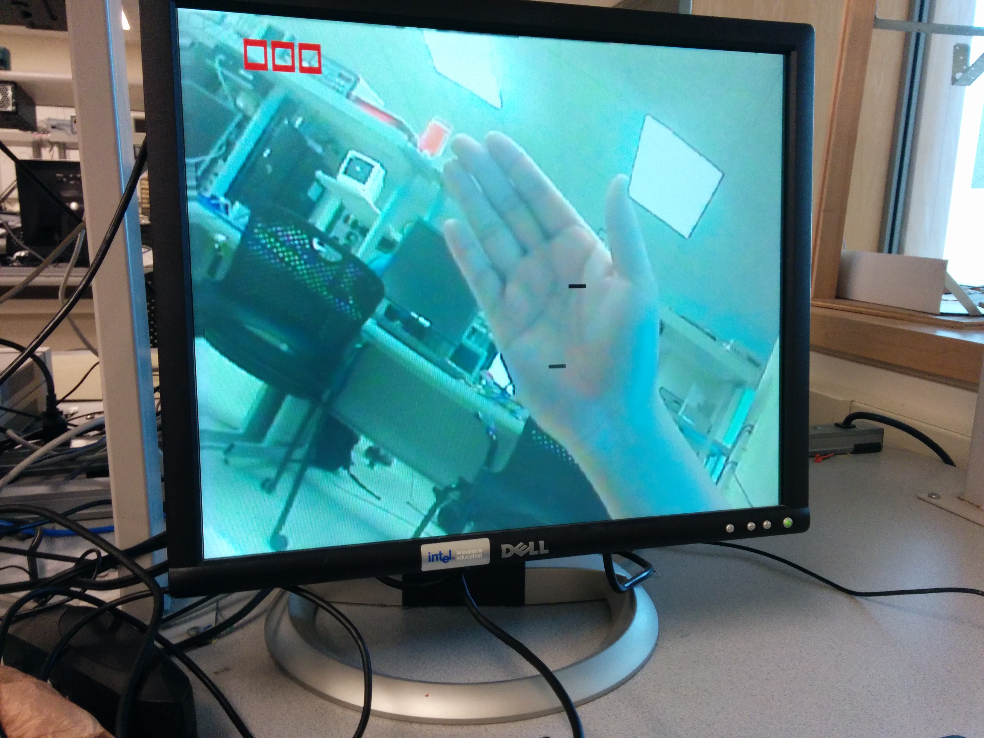
Figure 3. Screenshot of Hand-Tracking
Memory and Addressing
In this project, we decided to use M4K for fruit display as it can be easily created by the mega wizard from Altera Quartus. All M4K blocks have 16 bit for each data line that contains 5 bits for red, 6 bits for green and 5 bits for blue colour information. The number of total data lines depends on the resolution of the desired fruit image. For example, an apple has 40×40 resolution. Thus, the corresponding M4K, called apple_m4k, will need 1600 lines of data in total and the address will be 11 bits wide. All other fruit and bomb M4K block follows same scheme.
On the other hand, as mentioned previously, SRAM is also used for skin detection. Only 1 bit information presenting whether is skin or not is stored in this SRAM module. The address corresponds to down sampled camera capture so that it will help with the hand tracking module. Moreover, by the DE2_TV tutorial provided by Altera, another block of SDRAM is also used to store image information from camera. More information of the SDRAM usage can be found in Altera’s tutorial manual.
Parallelization Scheme
As explained in previous section, there will be several types of logical function modules that need to be run in parallel. Thus the synchronization between various modules is essential to make this final project to be successful. The major issue come from reading M4K and SDRAM at the same time and feed them to VGA at the same time. If the timing or flag judgement fails, the output image will look like snow that nothing will be captured from the camera. This happened several times in our Verilog code design and is mainly due to the bomb generation state machine.
As mentioned previously, we performed some tricks on M4K block readings. If the if/else statements change the current state in the wrong level, the screen will output nothing. For example, we have to check the bomb_cut_flag at the very beginning and make modification to current state in this if statement. Otherwise, there will be timing hazard to cause the whole VGA display to fail. In addition to the bomb modules, other small factors such as signed cast can also cause errors because those logics that seem to be combinational does not perform as expected in real world. Justifications have to be made to ensure the logical functions compute the correct value at desired timing.
Game Finite State Machine Design
There are mainly two finite state machine required for this gaming project design. They are the graphic FSM and the hand tracking FSM. As explained previously, the hand FSM will be responsible for detection then track. And the graphic state machine will be the core of image display. Normally, there will be 5 states for each gaming graphic state machine. The following paragraphs will explain them in details.
Init_state: At this state, we initialize all registers that will be involved in future graphic requirements. We disable all apple flags so that there is not output image. However, at the same time, we keep assigning the starting position and speed with random numbers so that we can achieve random fruit or bomb generation. On the other hand, we wait for debugging switch and random trigger to happen. Then the state will be transferred to the parse state.
Parse_state: In the parse state, we give enable signal to the position calculation module so that it will start calculation for next position of desired fruit or bomb. And state will be automatically transferred to the wait state.
Wait_state: This state is only to disable the input to the calculation module to let the position_calc module to run correctly. Although this causes delay in real position of the image, as the state machine is running at 27MHz clock, such an error in image starting position is truly negligible.
Draw_state: The draw state is responsible for finding the correct location of desired image and check whether the player’s hand has cut the fruit or bomb or not. This state starts with check of completion of fruit motion by y_direction. Then, it will check whether hand has cut the fruit or not and increase the scoreboard number and trigger the sound output if needed. If the fruit is cut, the display will change from fruit image to fruit cut image. In the end, if no actions mentioned before happens, the fruit or bomb will simply follow regular movement based on pre-random x_direction value. And the default state will simply disable all image output to provide safety of this code design.
Game_over: Game over happens when user cut an unexpected bomb. In this module, all flags will be set to zero and nothing can be changed. The rest of operation modules will be put in idle. The only method to get out of this state is by switch[15]. Further improvements could involve building a customized user interface to ask for continue or not.
Moreover, beside the graphic state machine, the M4K read address also changes with the draw state as position of image is also modified. Based on the direction judgement, we have different addressing scheme and sample code can be: if(x_direction==1'b1) apple_addr<=((VGA_X-x_speed-apple_x_rand)+(11'd38*(VGA_Y+y_speed-11'd400))); else if(x_direction==1'b0) apple_addr<=((VGA_X+x_speed-apple_x_rand)+ (11'd38*(VGA_Y+y_speed-11'd400))); else apple_addr<=11'd0; As mentioned previously, VGA_X/Y represents current VGA cursor point and the x/y_rand and x/y_speed shows the overall displacement.
Hardware vs NIOS II implementation
In addition to the hardware implementation mentioned previously, there is still potential for NIOS II to perform the graphing related functions. The software implementation also holds high potential to simulate many points if we are able to instantiate several NIOS II processor and connect them in parallel. Since the processors are run in max system clock frequency, there will be no disadvantage in parallelism for various image displays.
However, the hardware setup for several NIOS II processor is far more complex than instantiate the modules in Verilog since SOPC builder will be used. On the other hand, the synchronization will be much harder than hardware implementation due to the nature of high level programming language. Different cores will need to share resources such as SRAM. The lock or semaphore in C is not as convenient as using Verilog to hard code the on/off of certain blocks. Since time is limited, we only tried implementing this lab using hardware only.
Testing top
Testing of the code will mainly involve three parts. They are test for hand tracking, test for pipelining M4K read and write, and test for gaming state machine. Those tests are crucial to the success of this final design project because they covers nearly all customized designed modules and there are also synchronization issues involved for all three major aspects of design as mention previously.
First of all, the test of hand tracking state machines is also a learning process of previous projects. We mainly breakdown the previous project’s code work into pieces to test the individual functionality of each state to learn what is done and why this happens. We assign outputs to the LED, slow down the system clock to find out what are changed, how colour of hand is found, and how to locate its position. Through this process, we learned what registers and memory address are modified and checked by LED and 7 segments number display feedback. Then we start our integration for various states, modify the specification to meet our sensitivity and test whether the cursor will follow our hand/skin motion.
Secondly, instead of reading the M4K block of pre-defined image and writing state machine to wait for response similarly to previous lab-works of this course, we keep reading the M4K block in pipeline and move the address based on our own addressing schemes. This will create offset of current display center and actual desired image center. This offset could be an issue for high frequency decision makings. However, since the human’s response time is limited and the image refresh time is only 50 frames per second, such an error could be negligible. After various test about image display and cursor cut verification, we proved that this “cheating” function’s performance is acceptable.
In the end, we test our game by setting up debug switches and buttons. We assigned switch for all types of display image trigger and let the LED to perform state tracking. By this method, we do not only verify the correctness of the VGA screen result but also the success of running finite state machine. For example, the generation of fruit can be individually tested by different switches (for more details, please see comments of Verilog code) and the sound can be triggered by KEY[1].
Results top
The result of this lab design is successful that proper sounds and images can be generated according to different users’ actions. The FPGA output desired sound from the AUX port and the VGA display is also satisfactory. A screenshot of game is shown as follow.

Figure 4. Screenshot of Game
From the figure above, we can see that the score board shows how many fruits are cut. The demo video also shows that game will stop when a bomb is hit. Recorded sound can also prove that the sound module we inserted has been well integrated to this overall design project.
For detailed results, as mentioned in test section, we have also shown that the hand tracking performs well and the debugging switches and LEDs will be useful tools to verify individual functionalities or modules involved in this project design. In addition, the success of display has also proved our knowledge and understanding toward RGB and YCbCr colour schemes as we display our customized designed image with correct colour and can display spontaneously with the hand cursor.
Another interesting result about hand tracking is cursor continuity. To make the game more playable increase the continuity behaviour of the hand tracking, we design the cursor to be able to drop-off and pick-up. If the hand’s motion is too rapid, it may cause errors in detecting the center location of hand. Other than making errors, we prefer remain the current position of cursor and the cursor state machine goes back to idle mode. If the skin colour appears again at the cursor’s location, we can pick-up the cursor and begin cutting fruit again. On the other hand, we have also added a cursor initialization switch to enforce the cursor to restart from the center of VGA screen for user’s convenience.
Conclusions top
Our demo completely matches the initial goal of this final project design. The VGA screen display matches with our expectation that hand is correctly tracked, fruit is properly thrown to the air and scoreboard will keep track of how man fruits are cut. We have also successfully integrated previous lab work into this final project design that the audio module can produce desired sound effects. From this project design, the project group has enhanced understanding about FPGA hardware design using various types of memory blocks and get familiar to camera embedded FPGA design. We improved our skills and knowledge on image processing through the hand tracking design and debugging experience. On the other hand, we have also gained practical experience taking the advantage of parallel computation nature of FPGA. In addition, the complex finite state machine we build is another precious experience.
Appendices top
Previous design projects that used as reference:
- http://people.ece.cornell.edu/land/courses/ece5760/FinalProjects/f2009/ty244_jgs33/ty244_jgs33/index.html
- http://people.ece.cornell.edu/land/courses/ece5760/FinalProjects/s2013/hl855_kre27/hl855_kre27/index.html
- http://people.ece.cornell.edu/land/courses/ece5760/FinalProjects/s2013/tg293/tg293/index.html
Other Online Resources:
Code
Acknowledgements top
We would like to sincerely thank professor Bruce Land for his continued help and insightful advices throughout projects. His detailed lectures and practical lab sections offer us strong foundation to tackle our project. We also would like to thank the TAs that are in the lab in the extended lab periods that provide us with lab access to refine our work.