Introduction top
A stereo camera is a camera that, through the use of two or more lenses, can capture three-dimensional images. Our project turns the FPGA into a device that is able to reduce the time it takes to generate stereo images from rectified image sources. We then integrated our system into a ROS node, which allows our hardware to be easily used by any ROS system.
Our node subscribes to rectified images and publishes stereo images. We process the input images by passing them through a convolution filter followed by a sparse census transform. We then pass the output of the census transform to a census windowing module. This procedure preprocesses the image which is then passed into the correspondence module to finally generate the stereo images.
We were successful in our project and implementing the stereo image computation algorithms. We were able to accelerate this process from a 1 minute and 30 second generation time to a few milliseconds on our hardware.
High Level Design top
Rationale and Inspiration:
Stereo Cameras are expensive and an integral part of modern day robotics systems. Since processing these images for generating disparity maps is computationally intensive, we felt that by using an FPGA to implement the image processing algorithms, we could achieve a much higher processing rate than conventional systems.
The inspiration for this project comes from our group’s real world experiences. Our group has experience working with stereo and other camera technologies through research and internships and the high cost of these systems inspired us to make a computationally and cost efficient stereo image accelerator. Since ROS is one of the most popular modelling software for robotics and automation, it made sense for us to extend our project into a ROS node.
Background Math
Concept
The rationale behind stereo vision relies on having an image of the same scene from different perspectives and by comparing those images, generating a disparity map.
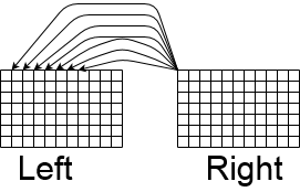
In our case, we used rectified images from two cameras, where one of the cameras was horizontally shifted. As shown below, the process of stereo correspondance relies on comparing a pixel in one image and finding out that pixel's location in the other image.
In order to succesfully correspond the pixels, the images go through a series of non-linear transformations in order to reduce noise and improve the output of the correspondance portion of the algorithm. In this section, we will discuss how a rectified image pair is processed.
The stereo algorithm works by combining the filtering and processing algorithms listed below into a single pipeline.
Convolutional Filter -
The input images first go through a convolutional filter. While our convolution module can use any kernel of any size, we chose to implement a 3x3 Gaussian blur filter due to its simplicity and good results. This helped to reduce any random noise in the images while preserving the edge structures which is needed for a reliable census transform (discussed in ii). We also tested an averaging filter and bilateral filter in MATLAB. In comparison, the simple averaging filter gave worse results due to poor noise filtering and the bilateral filter gave slightly better results due to its ability to preserve sharper edges. The time we would have to spend on developing the bilateral filter did not justify its minor benefits for our project, so we chose to use the Gaussian blur filter. In our Verilog design, the convolutional filter expects an 8-bit unsigned number for the image pixel input and a 4.4 signed fixed point decimal for the kernel input (this gave a range of -8 to 7.9375 for the kernel values with a precision of 0.0625). The output of the filter is strictly an 8-bit unsigned value. If the convolution at a certain location produces a negative value, that value is clipped to 0. The Gaussian blur filter uses the following kernel weights:

Sparse Census Transform -
After the images are prefiltered, they are processed by a sparse census transform. The census transform works by comparing a pixel’s surrounding neighbor pixels to itself in intensity. If a neighbor pixel is less in intensity, then a 1 is outputted, otherwise, a 0 is outputted. The sparse census transform works by using a larger window size so that the comparisons are done on further away pixels instead of immediately adjacent pixels. This boosts the robustness of the algorithm to noise. The algorithm is proposed by the paper here [http://ieeexplore.ieee.org/document/6213095/]. The following diagram represents the flow of the census transform. The transform is performed on a 5x5 window of pixels and the output is represented as a bit vector. The * represents pixels that we do not care about because we only perform the comparisons on the outer pixels. The center pixel is discarded because the output is always 0.

Census Windowing -
As a method to improve the output quality and also be more robust to noise, we perform a 3x3 windowing the on the census output. The module simply concatenates the nine 8-bit vectors inside the window into a single 72-bit vector. The following diagram shows the process on a 2x2 window.

Correlation -
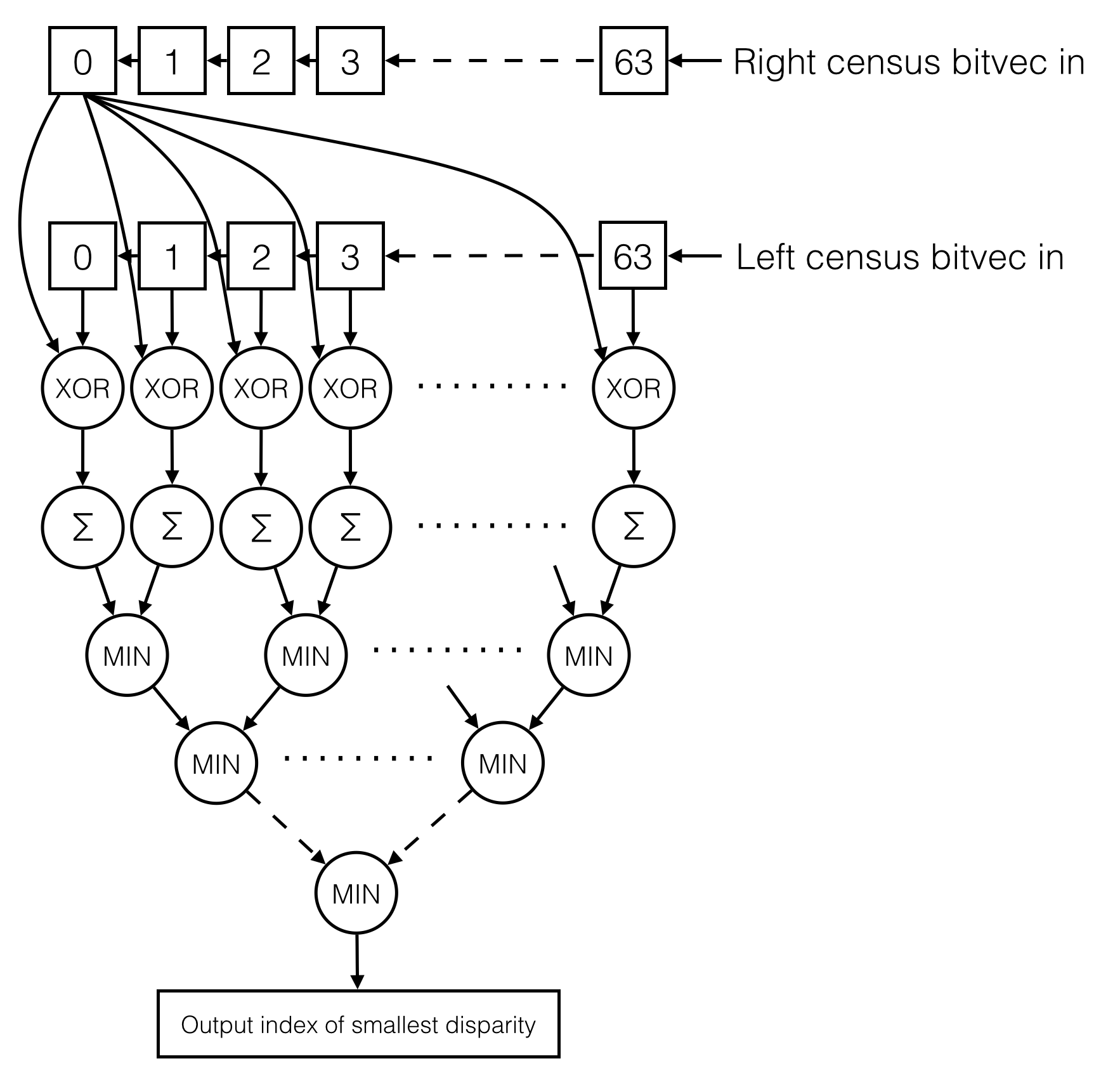
The correlation step take the windows census bit vectors from the left and right images and compares them to generate a disparity map. Our design can generate a depth map with 64 levels, so for each census vector in the right image, we compare it with 64 census vectors in the left image to find the level with the lowest difference between the two bit vectors. For each comparison, we XOR the two bit vectors and sum up the bits of the output vector (this is formally called the Hamming distance). If the XOR output for a certain bit is 1, then that means the bits are different between the left and right image, therefore the sum represents the amount of disparity between the two bit vectors. We then perform a tree comparison of the 64 disparity values to find the lowest disparity value. The index of of that value is the corresponding depth of that pixel in the original image. An index of 0 means that the object is infinitely far away and an index of 1 means that the object is very close. The following diagram shows the correlation process:

Post Filtering (not implemented) -
Our system also supports a post filter, but it was not implemented due to time limitations and hardware limitations. In our MATLAB model, we tested a median filter that gave good results in cleaning up the salt and pepper noise spikes from the correlation output. After we added in the VGA module for demoing purposes, our full design utilized 94% of the logic units on the FPGA. We will not have been able to fit a median filter module onto the FPGA. Without the VGA module, the FPGA can accommodate a post filter that connects to the correlation module output.

Logical Flow
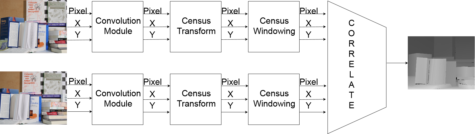
All of the verilog modules for generating the stereo depth map are connected together using a streaming interface. As part of the interface, each module will take as inputs the X and Y coordinates of the incoming data, the incoming data (whether it be pixel values or census bit vectors), and a input data valid signal. Therefore as outputs, to follow the same standard, the modules will give X and Y coordinates of the output data, the output data, and an output valid signal. This design allows us to easily test each modules individually and then connect them up without having to worry about any cycle level synchronization issues. As shown in the diagram below, the implemented algorithm on the FPGA involves a convolve module, sparse census transform module, and census windowing module for each of the left and right images. Finally a correlation module take the census data from left and right image to give a single depth map data as the output. One caveat to this design is that the left and right images must be fed to the system in sync with each other in terms of pixel locations. This is ultimately because of the correlation module requiring the pixels to be aligned for the algorithm to work.
In order to communicate with the HPS, this streaming interface is connected to the read and write FIFOs of the Xillybus interface. The write FIFO (relative to the HPS) receives image data from the HPS, deserializes the data, and passes on the data into the stereo vision streaming interface. The output of the streaming interface is then connected to the read FIFO (because it is read by the HPS) which connects back to the Xillybus. For demoeing purposes, we also multiplex the outputs from each stage of processing into a VGA buffer so we can display how the stereo vision algorithm works.
Relationship to IEEE, ISO, ANSI, DIN, or other standards
Our project relied on using the VGA standard as well as the ROS standard for publishing and subscribing between modules.
Software Design top
Robot Operating System (ROS)
To get ROS running on the DE1-SoC, we first installed Xillinux on the HPS. Xillinux is a custom linux distribution based on Ubuntu 12.04 LTS for ARM. It is provided for free by Xillybus, and works out of the box on the Altera SoCKit board. To get this running on our board (DE1-SoC), we had to make a few modifications in the Quartus project, generate a .rbf (Raw Binary File) in Quartus, and add this to the SD card image. Mohammad, who had worked with Xillybus before, helped us with this process. The template project he provided enabled us to get the system up and running quickly, so we could focus on integrating our system with the Xillybus.
Once we had Xillinux running, the first step was to install ROS on the board. This was relatively straightforward, as the ROS wiki already had a guide for installing ROS on Ubuntu for ARM. However, as this was an old version of Ubuntu (12.04), we had to install an old version of ROS that was compatiable with this (ROS Groovy). To facilitate development, I created a catkin workspace on the drive, and created a ROS package to contain our code. This package contains our source code as well as .launch files to get our code running.
The ROS node was fairly simple. It subscribed to messages published under the '/camera/image' topic, and published messages to the 'stereo/image' topic. In the message receive callback, our node would write the input image to the Xillybus device driver file ('/dev/xillbus_write_32') and read back the stereo image from the other device driver file ('/dev/xillbus_read_32'). The Xillybus IP handled internal DMA transfers required to communicate from the device driver files to the FIFOs on the FPGA.
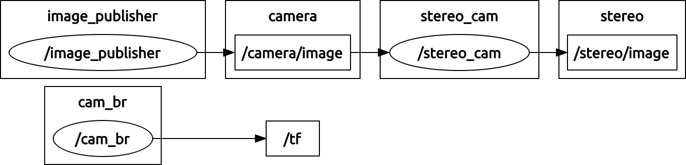
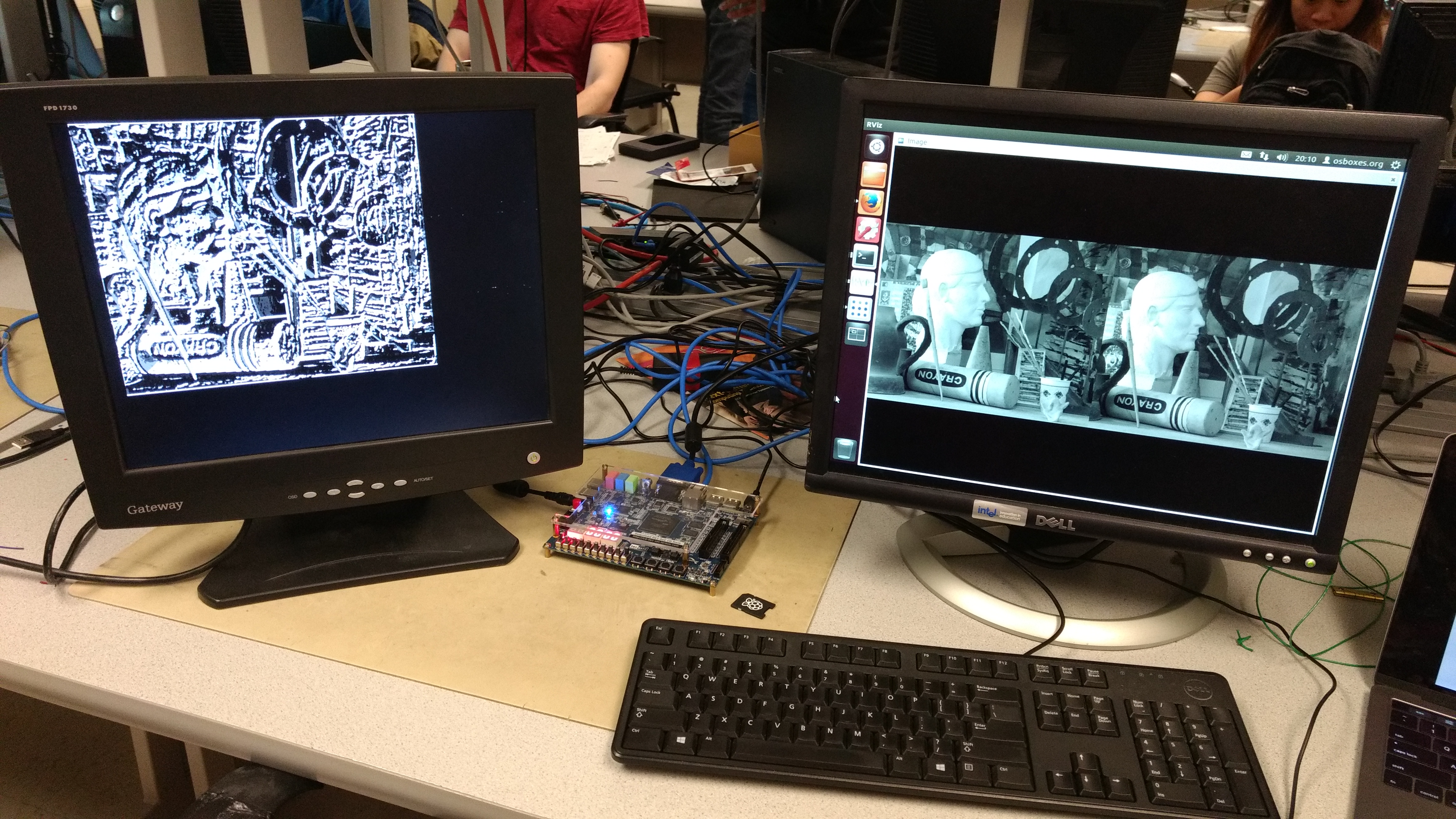
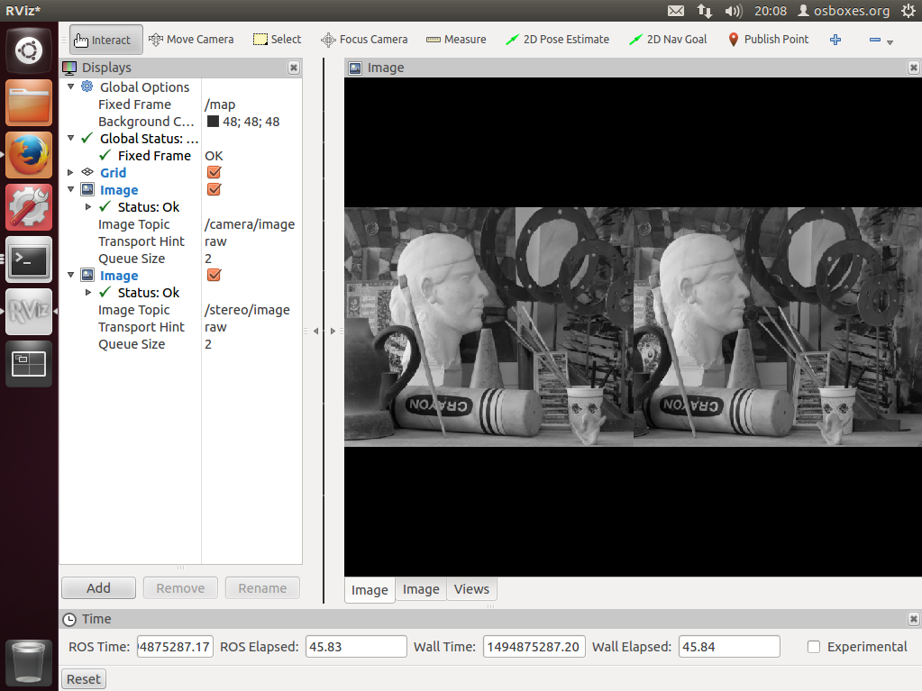
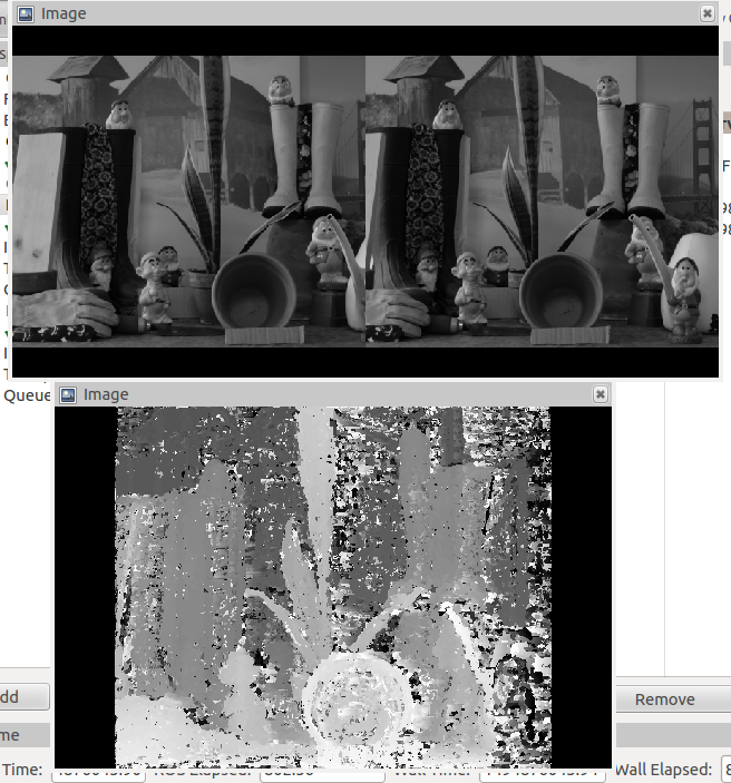
To test our node and visualize everything that was going on in the system, we installed an Ubuntu virtual machine on one of the lab computers, and got ROS running on that as well. Then, we connected the DE1-SoC to this computer's network, so that ROS nodes running on either machine can communicate between each other. We created a simple image publisher node that reads from a file and publishes rectified images at a steady rate, and launched the node running on our board. These images were taken from the 2005 Middlebury Vision dataset. Lastly, we launched RViz to visualize both the input and output images. The following screenshots show this.
Hardware Design top
Convolution and Census Modules
The basis of our FPGA design relied on the streaming of pixels through our extensively pipelined hardware. In order to handle this streaming interface, a shift register architecture was developed and on each clock cycle, a pixel would be shifted in and a pixel would be shifted out. Below is a visualization of how this interface worked with the convolution module. For simplicity sake, we assume that each row of a "frame" is only 5 pixels wide. In reality, this is actually hundreds of pixels wide.
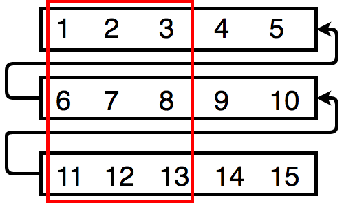
The shift registers gives us an NxN window of pixels to operate on (in this case a 3x3 window highlighted in red above). This design allowed us to perform the convolution, census transform, and census windowing. As shown in the diagram, after the 0th pixel is at position 0, each new pixel that is shifted in essentially moves the window rightward through the image (and wrapping around to a new row of the image once the window falls of the rightside of the image). This gives us the sliding window of data that we can use to do all of the preprocessing that our algorithm needs. The actual implementation of the shift register involved using a shift register IP from Altera and a few registers. The data in the red box uses registers so that we can directly access the data. The rest of the data in each row uses the Altera shift register IP module, which is based on M10K blocks.
Correlation Module
The correlation module worked by using 2 rows of shift registers to compare a bit vector from the right image with 64 other bit vectors in the left image. As discussed in the math section, the correlation module does the comparison by first XORing the bit vectors, then summing up the the bits from the XOR output to compute the disparity values, and finally extracting the index of the lowest disparity value. As shown in the diagram below, as new bit vectors are shifted in, a new depth value is computed at the output. This is directly connected to the streaming outputs of the left and right census window modules, and the outputs are fed to the HPS and VGA buffer. A comparator tree is used to find the lowest disparity value. To speed up the design, the comparator tree is pipelined at every depth of the tree, starting at the outputs of the summations. As a result, this module is capable of running at just over 100 MHz and will generate 1 depth pixel per cycle at full throughput.
Xillybus and HPS Communication
To communicate with the HPS, we use the Xillybus. The bus acts as a FIFO streaming interface between the HPS and the FPGA. On the FPGA side, we simply instantiate the Xillybus IP and connect its inputs and outputs to two FIFOS. The write FIFO receives data from the HPS (termed as such because the HPS writes to it) and the read FIFO sends data to the HPS. Because the bus width is 32 bits wide and each packet of data from the HPS to the FPGA needs 36 bits (10 bits for X, 10 bits for Y, 8 bits for left image pixel, and 8 bits for right image pixel), we had to serialize the data on the HPS and deserialize it on the FPGA. Therefore, the read port of the write FIFO is connected to a deserialize module that connects to the stereo vision pipeline with our standard streaming interface. The data output from the stereo pipeline can fit into 32 bits (10 bits for X, 10 bits for Y, and 8 bits for depth data) and does not need to be serialized before sent back.
Things that did not work
We initially tried to stream stereo images from a camera module. This was met with several obstacles, ranging from noisy images to rectification and alignment.
We decided to use an Arducam camera due to its theoretical simplicity ability to output raw RGB. Our initial camera selection, OV7670 (TODO: link and image here), had to much static noise to be off any use. This noise presented itself by having noticeable flickering screen no matter the lighting conditions. This kind of noise would have required a much more complicated memory interface to fix. We did a quick test with another Arducam, the MT9D111 module and noticed that there was much less flicker and decided to purchase a set of those.
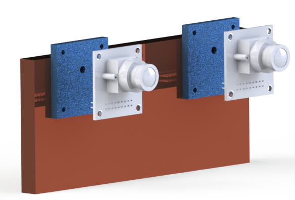
The mounting system was already designed and manufactured for the OV7670 and needed to be redone for the MT9D111 since the mounting was non-compatible with the previous modules.
Another issue with the MT9D111 was the difficulty of interpreting the datasheet and configuring the camera. The camera was configured over i2c, which we used via smbus module on the Linux side of the FPGA. We were able to debug the smbus module and eventually figured out how to configure the camera to the correct size. However, the difficulty of alignment and more advanced configuration, made these cameras undesirable. Additionally, the nature of our streaming algorithm requires the left and right pixels of the same coordinate to be received at the same time. There cannot be any offsets in the coordinates of the left and right pixels. Because we were unable to force the MT9D111 to lock to a fixed frame rate and be synchronized to each other (at least close enough such that we can use SRAM buffers on the FPGA to correct for minor out of sync issues), we decided not to use these cameras. The solution to fix this will be either to use a FPGA with a large enough SRAM to store the full frames for both cameras, or use the SDRAM as a frame buffer for both cameras.
In parallel to Arducam development, a camera with a stereo lens was lent to us by Bruce. This camera outputted a combined image from both lenses. This was not the ideal output since we wanted to have two distinct images, so after some experimenting, we determined how we could configure the camera to taking regular pictures with the stereo lense. This resulted in an single image which was split down the middle with the image through one lense on either side. We purchased a usb-ntsc cable and were able to get the camera to stream those images to the FPGA over ntsc. We then applied cropping functions on the input and separated the single image stream into two distinct streams. We then ran those images through our algorithms. We had hoped that this would result in a rectified image input to our modules, but the output of this was extremely noisy.
We decided that due to our time constraints, to move to a system that accepted rectified images and expand on the ROS portion of the project.
Results:
Our system was very successful as a stereo image accelerator. We were able to achieve a 1 pixel per FPGA clock cycle processing rate which equates to 100 million pixels per seconds for the possible 100 MHz clock rate of our design. The bottleneck of the system existed in the 200MBps Xillybus bandwidth for transmitting images over the HPS. In our demo, we tested with image sizes of 447 x 370.
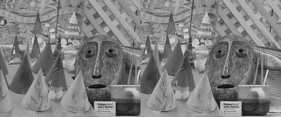
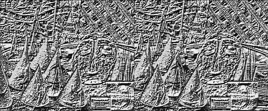
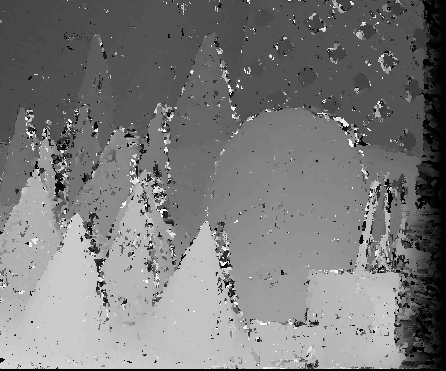
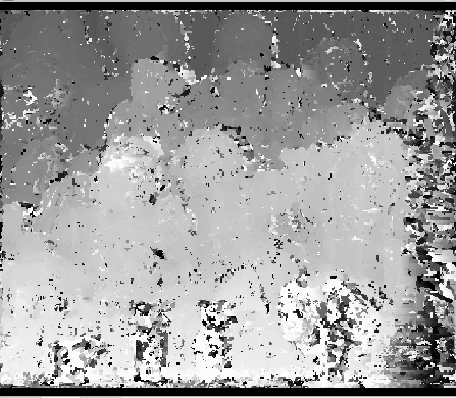
As for accuracy, our system was able to achieve ~85% accuracy compared to ideal images. Below shows the input images and the output of our system.
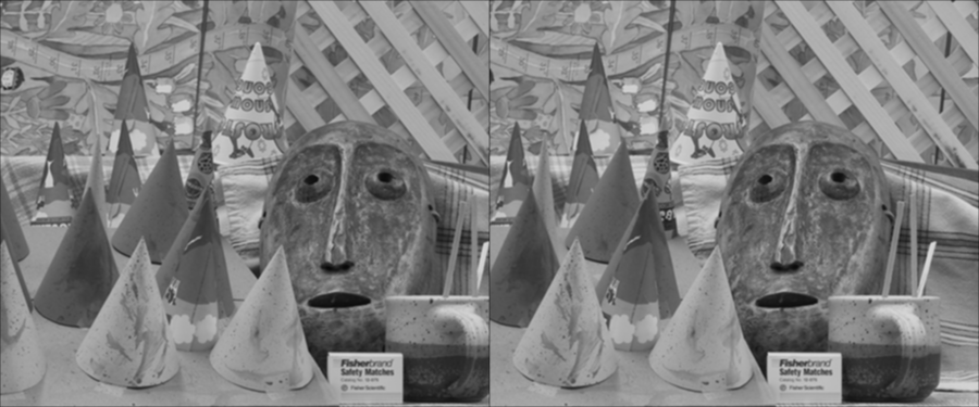
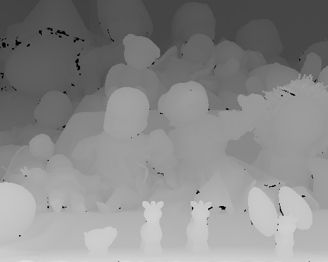
Here is the output of our system compared to the ideal output. It is clear that while our output is not ideal, we are able to identify the major elements of the ideal output.
Safety
We made sure our project was safe by careful layout and testing. We made sure that we took breaks every couple of hours to avoid muscle fatigue. We also followed strict ESD protocols to avoid frying an FPGA.
Usability
This project is developed to be a plug in ROS node so it is easily usable by any ROS system. This makes our project extremely easy to integrate into any ROS system that already has a module outputting rectified images.
Conclusions top
We were very pleased with the results of our project. Our accelerator is capable of streaming ~30-40fps at 1080p if given a stream of rectified images. We were able to meet our goal of generating stereo images
at high speed while retaining a high accuracy. To improve on our accuracy, we could implement a median filter, LR consistency check, and increasing the census window size. We would also have liked to have been able to use
our own camera's, but as discussed above, the time constraints forced our hand.
If we were to do this project again, we would abandon the idea of using our own cameras and work on what ended up being our final result sooner. This would have given us more time to implement some of the improvements talked about above.
Ethical Considerations
We believe our project followed the ethical standards of Cornell University and general engineering practices.
IP Considerations
We used the Altera IP for shift registers, FIFO, and dual clock RAM. We used the Xillybus IP as an evaluation basis. Additionally, the MATLAB code used to initially design, test, and verify our stereo vision algorithms were based the code here
Appendices top
The group approves this report for inclusion on the course website.
The group approves the video for inclusion on the course youtube channel.
A. Code Listing
Our source verilog, MATLAB, and python scripts used to develop the FPGA architecture are available on Github here.
Our source C++ and .launch files for ROS are available on Github here.
Simply clone both repos into the same directory and run the Xilly Project.
B. Distribution of work:
- Jay worked on designing and manufacturing the camera mounting systems as well as interfacing with the cameras. When that was unsuccessful, he pivoted to assisting with the ROS implementation.
- Raghava worked on the ROS implementation, the convolution module as well as the overall FPGA architecture design.
- Tian worked on the algorithm design, evaluation, and verification, FPGA architecture design, and the correlation module.
C. References:
General resources:- OV7670 Tutorial
- OV7670 Datasheet
- Xillybus
- OV7670 Description
- MT9D111 Description
- MATLAB Script Inspiration
- Mohammad Saifee Dohadwala, for helping with Xillibus and Xillinux installations.
- Census on Virtex-4
- Modified Census on Spartan
- Census on Cyclone II
- Sparse and Generalized Census
- Median Filtering Comparison
Acknowledgements top
We would like to thank everyone who supported us in this project. The course staff, Tahmid, Manish, and Mohammad for their constant presense in lab and help. We would also like to thank Bruce for his support and encouragement throughout the project and the semester.