Four Camera Pyramid Display
Demonstration Video
Introduction
With the growth and popularity of holography, 3-D imagery and augmented reality, it goes without saying that a 3-D holographic display of a real time recording would be well received. The motivation for this project stemmed from an idea, which hit us when we were pondering over how cool would it be if Professor Bruce could give lectures as a hologram. As a result, over the course of 5 weeks, we built a setup that records and displays objects in 3-d in real time. We made a simple studio for recording and leveraged a 3-d holographic pyramid for display. Most of the work in this regard has been done on recorded videos. Our final product is able to display a hologram of real time recording. Though our implementation is on a small scale, one of the future improvements could be to implement changes to record and display larger objects.
High Level Design
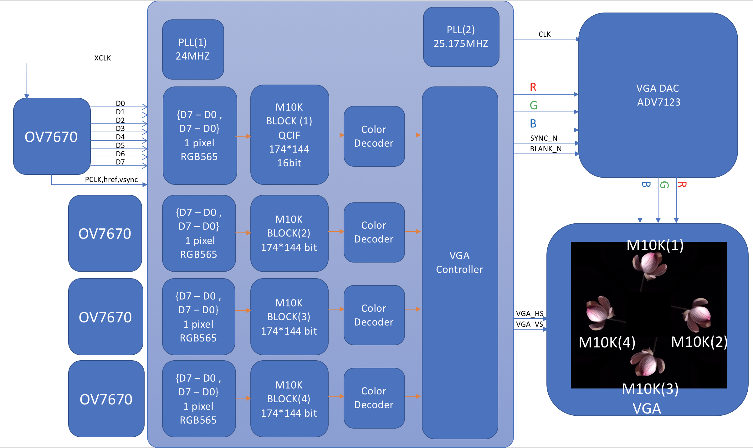
Figure 1: Hign Level Design
We use four cameras to record an object of interest from four sides. These cameras are placed inside a studio, which makes the environment around the object suitable for recording. The studio mostly provides for a fixed position for the cameras and a black background behind the object. The four cameras send the image data to the FPGA on the DE1-SOC board. This is stored in M10k blocks, which is then fed to the VGA DAC. From there it is sent to the VGA display.
The image stream from each of these four cameras is displayed on a VGA monitor. The positions of these video outputs on the monitor is such, that when a four-sided transparent pyramid is kept below a tipped over monitor, each side of the pyramid reflects an image stream. The four sides of the pyramid reflect/display the four sides of the object, thus giving a 3-d effect.
Software Design
The whole system can be divided into two subsystems: The Verilog and Arduino SCCB.
camera introduction
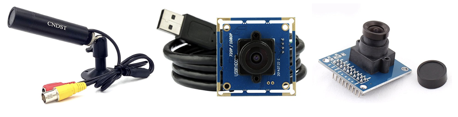
Figure 2: Cameras: NTSC, USB, OV7670 (from left to right)
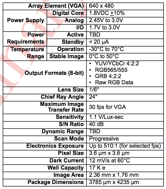
Figure 3: data sheet ov7670
We have three choices for the DE1-Soc board: NTSC camera, USB camera and OV7670 which uses GPIO pins to transmit data. There is only one port for NTSC camera and only two ports for USB camera, but we need to drive 4 cameras at the same time so that we cannot use these cameras. For Ov7670, we need to use 18 GPIOs to drive one camera. DE1-SOC board has two GPIO ports and each of them has 40 GPIOs. So the port number is enough to drive 4 cameras at the same time.
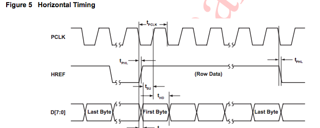
Figure 4: Horizental Time Diagram OV7670
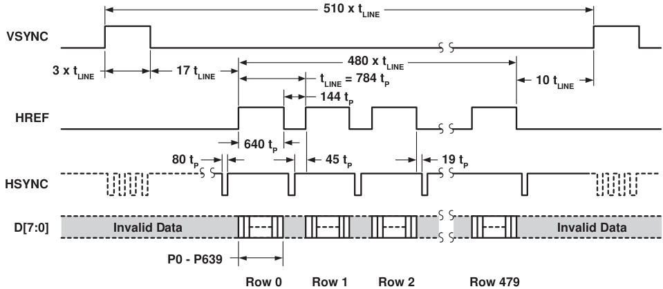
Figure 5: Vertical Time Diagram OV7670
According to the data sheet, Ov7670 needs an outer clock source. According to the scale setting of OV7670, it will output a PCLK to DE1-SOC to read the data. As we want to capture QCIF format video in 30 FPS, we use IP from Altera to generate a 24MHZ clock signal as the XCLK.
OV7670 will output PCLK, VSYNC, HREF and D[7:0] to DE1-SOC. We set the color scheme to RGB565 so that it takes us two cycles to read a pixel. After reading in the data according to the time diagram, we store the data into M10-Block from Altera. The M10-Block has 174*144 units and each unit can contain 16bit (one pixel color information).
Arduino SCCB
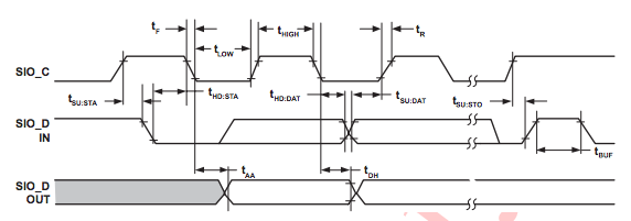
Figure 6: Arduino SCCB Time Diagram
Each time we power OV7670, the camera will reset. So we need to configure OV7670. The main settings are scale setting, color scheme setting and color matrix setting. The color matrix is a matrix to adjust the color of the image, if we don’t set this color matrix, the color will be wrong. We use RedBear Duo(like Arduino) to configure OV7670s according to SCCB protocol which is like IIC.
Verilog
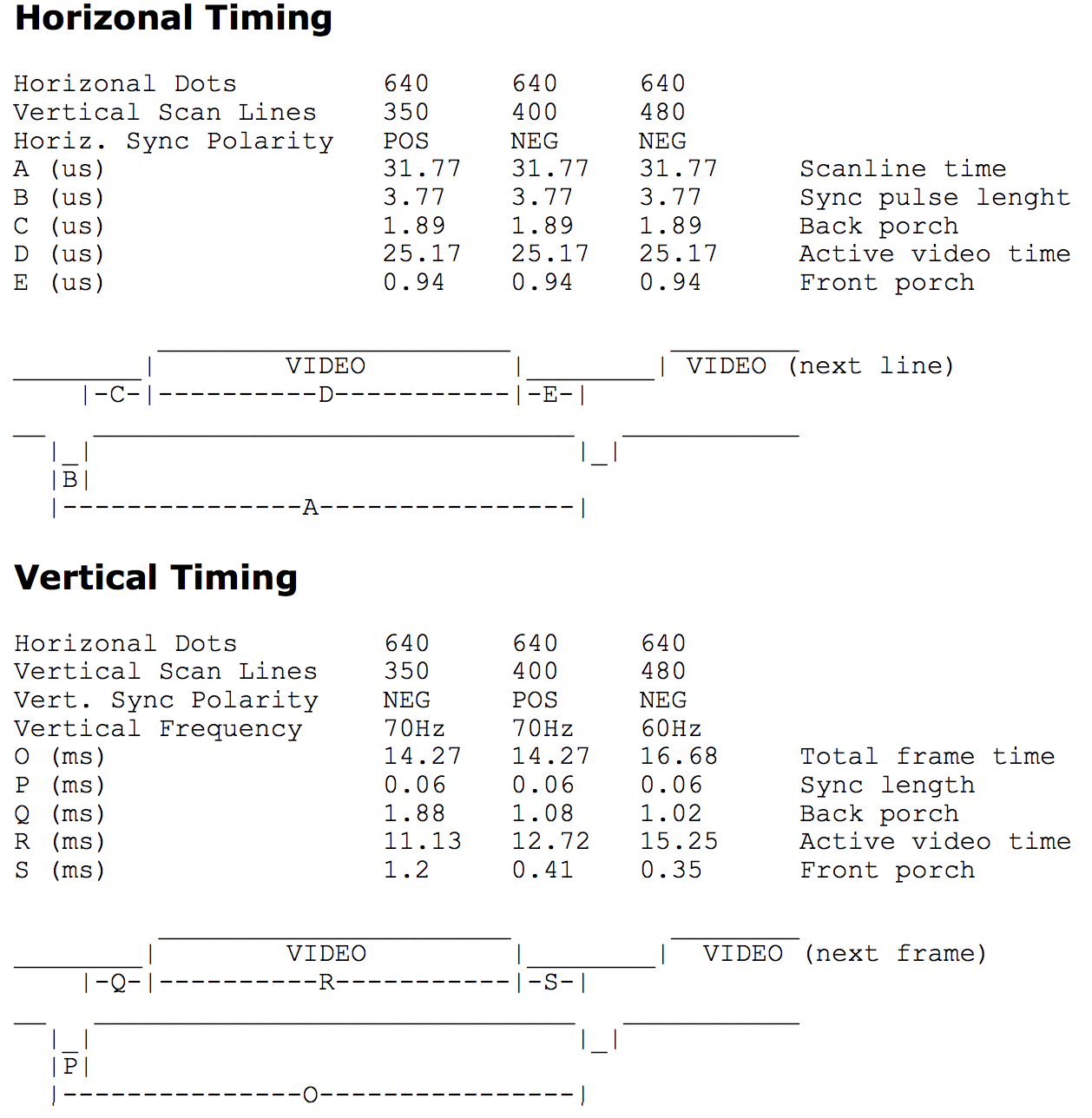
Figure 7: vga time diagram
According to the VGA data sheet, we use the PLL from Altera to generate 25.175MHZ as the clock input for the VGA DAC. We cannot generate exactly 25.175MHZ but it didn’t affect the final result.
We use the module written by a previous TA. This module is written for 640 * 480 60FPS VGA monitor. In this module, the output port is x and y coordinates which will update from [0,0] to [640,480] according to the VGA time diagram.
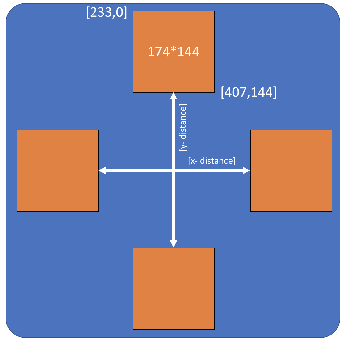
Figure 8: VGA Coordinates Strategy
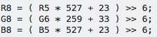
Figure 9: Color convert equation
When we are updating the coordinates, we will check if the coordinates belong to one of the M10K Block. For example, in figure x, the upper frame has a coordinate range from [233,0] to [407,144]. If the coordinates are in this range, we know we need to read out the pixel information from the first M10K-Block. As the address in M10K-Block is from [0,0] to [174,144], we need to subtract a bias from the required address to get the right address in M10K-Block. After getting the right address, we will read out the right pixel color. As we use RGB565 to represent the color while in VGA we use RGB 888, hence we use a linear equation group to expand RGB565 to RGB888. After that, we will send the R,G and B channel data to VGA.
We also use two buttons on the FPGA to adjust the x distance and y distance as shown in figure 8. It helps us adjust the distance between each blocks so that we can easily optimize the final effect.
Hardware Design
The whole system can be divided into three subsystems: The camera system, Studio and VGA display system.
Camera System -
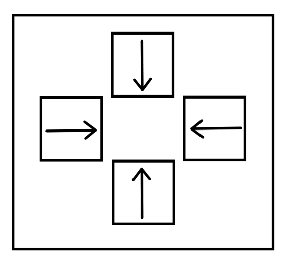
Figure 10: camera positions
Once we confirmed that all the 4 cameras were working, we started planning the placement of the cameras for our studio. Parameters such as distance between the object and the camera, and the height at which we’ll be keeping the cameras had to be considered. We needed the 4 cameras to display their output to the VGA monitor in the following manner as in figure 10
Where the direction of the arrow points to “up” with respect to the recorded video. To have this kind of setting, we could do two things- 1) rotate the videos streamed by the cameras and display them on the VGA 2) Rotate the cameras to obtain pre-rotated video streams that would save the post processing required for displaying the videos. We went with option 2, as we were confident that we could affix the four cameras rotated differently while keeping the opposite cameras on the same optical axis.
Next, we had to decide the height at which we’ll be keeping our cameras and the distance between these cameras. After experimentation, we observed that a distance of 25 cm between the camera and the object was ideal. Now we had to decide the height at which we’ll be positioning our cameras. The height had to be such that object at that particular distance should be covered by the camera viewing angle. From the data sheets of ov7670, we found out that the camera angle is 50 degrees about the optical axis. Therefore, using basic trigonometry, we calculated that the minimum height of the cameras has to be:
25 cm x tan(25 degrees) = 11.66 cm
This is to cover the entirety of an object if it’s kept on the ground and the camera height is also calculated from the ground. Once we decided on the studio, which is explained in detail in the studio section, we preferred keeping the cameras at a height of 15 cms so that the ground is not covered while recording. Hence, we had to keep the objects little elevated from the ground as well to view them in entirety.
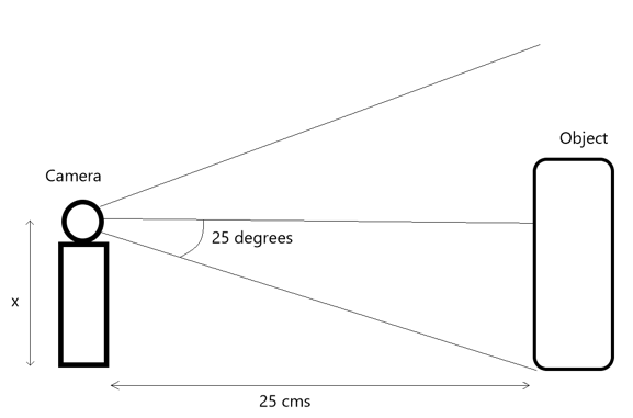
Figure 11: Camera Angle
Studio -
Initially we had thought that we’ll be building a green studio, which will have green walls and Cameras will be inside that studio. We speculated ideas like painting the cameras green and so on. Then as we saw that the cameras were mostly black, we realized that instead of a green screen we could use black background and paint the rest of the cameras black. Black being an absorber of light, would’ve helped us in making the image processing easier. We wouldn’t have to do background subtraction or anything like that.
At this point, we had a rough idea of our constraints and conditions:
1) We had to have black walls behind the object-
Example for a single camera –
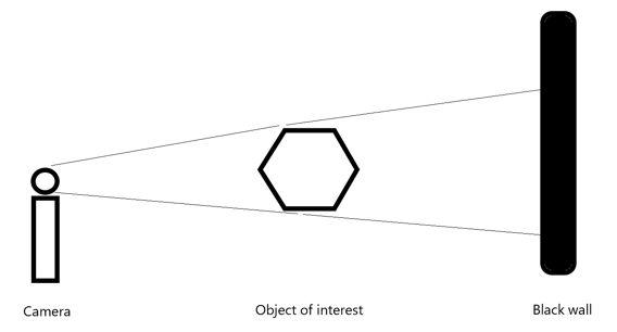
Figure 12: side view
2) We needed to place 4 cameras in the following fashion -
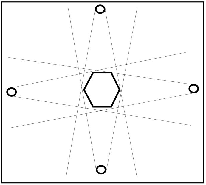
Figure 13: Top view : circle = camera , hexagon = object of interest
3) As all of the cameras are connected to the DE-1 SOC board we had a limitation of wire length as well
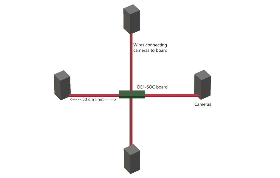
Figure 14: connection between FPGA and four cameras
4) Therefore, the maximum size of the studio was limited. As the wires also had to reach the camera. As clearly visible from the infographic diagram below, x+y+z had to be < 50 cm.
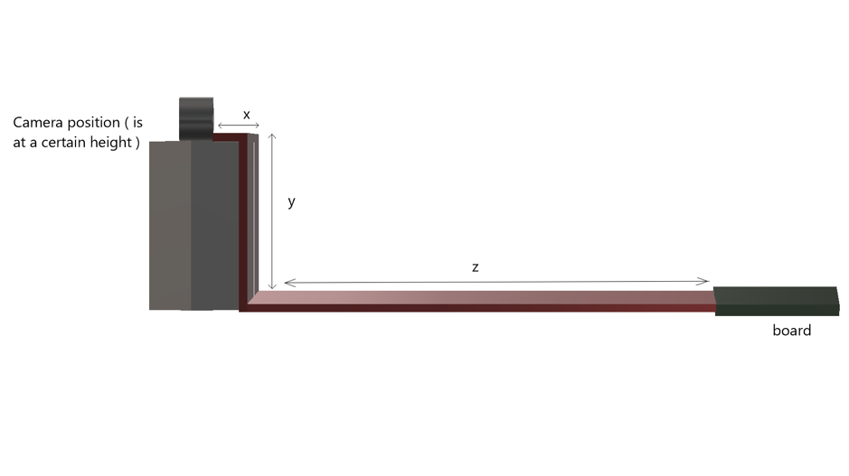
Figure 15: Line connection details
While searching for black Styrofoam for our studio, we stumbled upon a cheaper and a more sturdy alternative. We found a cardboard box of length and breadth 20” x 20” and height 22”. We also found black chart papers. We instantly decided that we could use the cardboard box to make our studio and use the black chart paper to cover the insides of the box.
We also observed that we could drill holes onto the cardboard with a drilling machine, sizing it exactly fit in only the lens of the camera rather than keeping the entire camera and the camera stand inside.
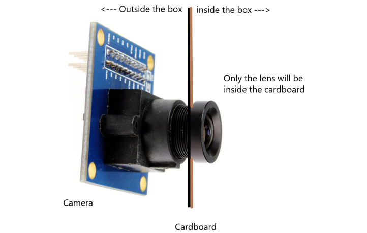
Figure 16: Method to fix the camera
This enabled us to not worry about positioning the cameras on stands. We were able to use tape to make affix their position. Moreover, we didn’t have to bother with painting the rest of the camera as only the black portion of the camera i.e the lens and the lens enclosure would be inside the studio.
Display-
The video from each of the four cameras was displayed on the monitor at the following positions marked in red-
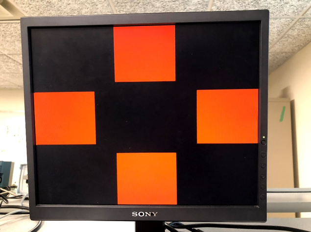
Figure 17: red cross test
Corresponding side of the 3-d holographic pyramid would then reflect the four cameras’ live streamed video displayed on the monitor.
We initially set out to make our own pyramids. As you can see from the figure 18 below. The one on the right is the one we made and the one below the monitor is the one that we bought.
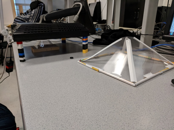
Figure 18: big pyramid
We made the 3d holographic pyramid using transparent binding sheets, which we cut into a particular trapezoidal shape. The measurements for the trapezoid were done in a way to almost have a 45 degree viewing angle.
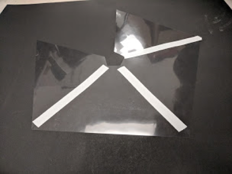
Figure 19: small pyramid
Then we used tape to join these trapezoids to make a pyramid. One problem we faced was that the binding sheets were too thin and did not retain the pyramid shape. So we made a frame using pencils to make the pyramid sturdy. Even then, the size of the pyramid and the thinness of the sheets compromised the shape and we were getting distorted display on the pyramid. Therefore, we went ahead with a premade pyramid bought from a custom holographic pyramid builder.
Initially the idea was to have the pyramid inverted on top of the monitor. However, after experimenting with our previous self-made pyramid we started to use a setup in which the monitor is tipped over and the pyramid is kept straight below the monitor.
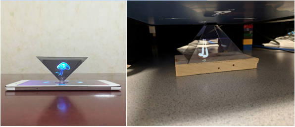
Figure 20: Compare our result with the result from the Internet
This setup blocked most of the environmental light falling on the pyramid, thus delivering better quality of display.
We also played a little with the brightness and contrast settings of the monitor to obtain a satisfying display. We had to trade-off between the intensity and the sharpness of the image to finalize these settings.
Testing and Result
Result of the Design
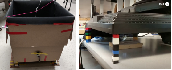
Figure 21: on the left: the studio; on the right: the display
This is what the whole system looks like. The left picture is the studio and the right one is the hologram(currently displaying earphones).
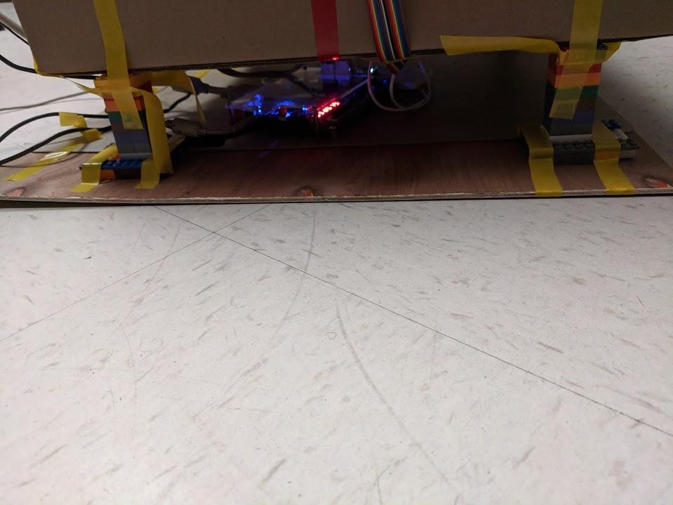
Figure 22: FPGA under the studio
As mentioned earlier, we had to place the board blow the studio becasue of the wire length constraints.
We achieved very good 3D effect on the hologram pyramid as shown in figure 21. Because of different clocks of camera and VGA update, some of images in the video might overlapped. This situation doesn’t happen when objects move slow and things change position slowly in front of the camera.
We ensured that we kept the anti-static mat below the board to comply with preventive meatures.
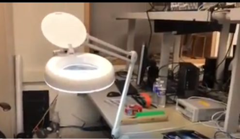
Figure 23: light
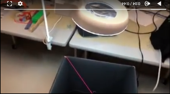
Figure 24: light beyond the studio
To obtain clearer images we had to ensure that the backgrouds were dark and the object was well lit. The room lighting didn't seem good enough, so we went with external lighting source. But, The external lighting caused an imbalance in the dark background of the 4 walls of the studio. We kept experimenting with the light source position until we obtained satisfactory results.
Our system is large but easy to use. The studio can be moved together since there is a wood board on the bottom and everything is fixed on it. As long as you plug on the FPGA and upload the verilog, the video will show on the VGA, and then you can see the 3D effect on the pyramid. The only thing that might need to be adjusted is the light. What angle to put the light in, depends on the environment.
Conclusions
The 3-d effect works very well. We are very contented with our results as this was a result of several brainstorming sessions. First of all, we were able to run four cameras on FPGA at same time. Then we used buttons to adjust the distance of two images in one direction which would be convenient for testing. The dynamic adjustment allowed us to change the size of pyramid.
The result is even better when we change the way place the VGA and the pyramid. At the beginning, we actually planned to place the VGA and pyramid like figure 25, and made a big pyramid by ourselves.
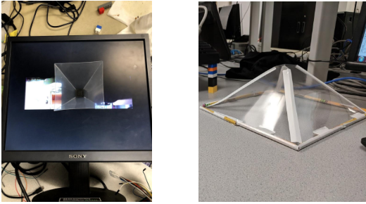
Figure 25: pyramid with different sizes
The big pyramid was too soft which compromised the shape of the pyramid. Since iot was more stable when kept like a pyramid rather than an inverted pyramid, we tried to put VGA on the top of pyramid like the picture below.
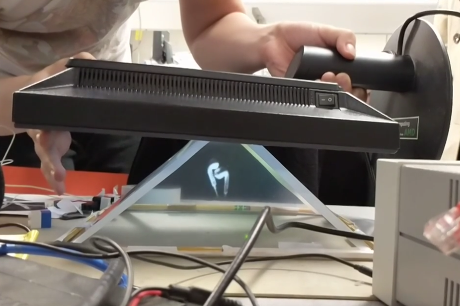
Figure 26: new position of VGA
Keeping the display on top, blocked a lot of the environmental light onto the pyramid, which resulted in a clearer reflection by the pyramid.
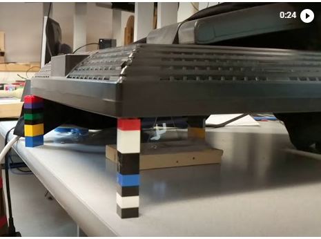
Figure 27: use LEGO to hold the VGA
An improvement could be that we can use larger, more stable pyramid to show the 3D image and make the environment darker. And adjusting the lighting in the studio to get more clear images of dark color objects.
Other applications can be decorative holograms, holographic photo display, long distance holographic calling. Our studio can be used standalone to generate videos for holographic display as well.
We have followed all the standards in our design, wherever necessary. For the intellectual property consideration, we used the code of camera from a previous project. We used the Altera IP for shift registers, FIFO, and dual clock RAM. We used the Xillybus IP as an evaluation basis. There is a possibility of having design patent in the future as most work in this regard is on recorded videos rather than real time displays.
Future Work
1. Image processing
At the beginning, we were planning to use green background as it is usually used for background subtraction. But then we shifted to a black background as it makes the processing easier. But this comes at a cost as darker colors are much more difficult to display. Future work can include compenstating for this. We contemplated using median filter and mean filter. And after testing on Matlab, we decided to use mean filter. But with the current setup the image seemed clear enough which didn’t need to be filtered. So we felt it wasn't necessary to implement the filter. A future possibility could be to implement the filter as well.
2. Larger setup
Because of the restrain of length of lines that connect camera and FPGA and the size of pyramid, we couldn’t display large objects. In the future, we can consider making the studio and pyramid bigger to display larger objects.
3. Lighting
Lighting was an issue for us. We adjusted the light for a long time to get a good effect. So in the future, if we can make a closed studio and set light inside with fixed positions, it would be better.
Appendices
Appendix A: Website and Video Approval
The group approves this report for inclusion on the course website.
The group approves the video for inclusion on the course youtube channel.
Appendix B: Code
Camera Buffer M10K-Block cam_buffer.v
Red Bear Duo SCCB configure module
Appendix C: Work Distribution
Beitong Tian
Code and debug the Verilog and arduino program to drive the 4 cameras on VGA.
Help to build the studio and adjust the camera position.
Yiting Wang
Research on the image processing.
Examine different kinds of image filters on Matlab and choose mean filter to use for our project. Then wrote the verilog code for mean filter.
Construct the studio and pyramid.
Arvind Puthige
Mostly focused on conceptualizing, designing and constructing the external hardware setup.
Also concentrated on mathematical calculations and geometrical considerations for camera setup, and pyramid angles.
Appendix D: Materials and Costs
| Parts | Cost/Dollar | Source |
|---|---|---|
| 3 * OV7670 | 32.97 | Amazon |
| 1 * OV7670 | free | Prof. Land |
| 80 * Jumper Wires 50 cm | 19.48 | Amazon |
| Studio Material | 32.48 | Staple |
| LEGO | 29.95 | Ebay |
| Pyramid | 22.49 | Offical Website |
| Total | 137.37 |