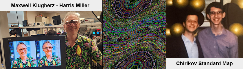
Introduction
For our final project in ECE 5760, we implement a solver of the Standard Map (also known as Chirikov's Standard Map) on the DE1-SoC. First introduced by Boris Chirikov in 1969 [1], the Standard Map is a discrete-time Hamiltonian dynamical system described by the following set of equations:
pn+1 = pn + K sin(xn)
xn+1 = xn + pn+1
where the equations are taken modulo 2𝜋, such that all inputs on the 2𝜋 by 2𝜋 square are mapped onto the same area. The variables x and p represent the system's angular position and momentum, respectively (and as such sometimes x is replaced by θ).
The standard map can be used to model the physical system of a kicked rotor; the equations describe a free-rotating pendulum (not experiencing gravity) that periodically receives an instantaneous impulse K. The phase space for this system is cylindrical, such that our modulus over x corresponds to the pendulum "wrapping" over the top. This phase space is also periodic in momentum, which allows us to only need to view p from [0,2𝜋) –and as such, we view the phase space of the map as a torus!
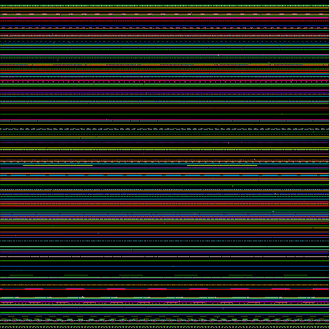
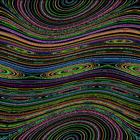
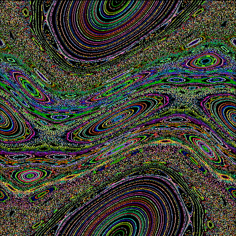
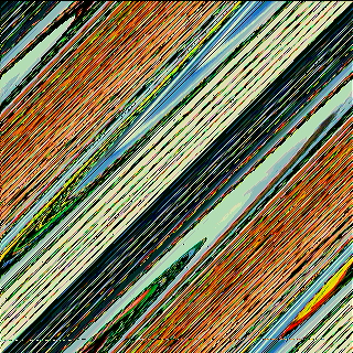
As K increases, orbits begin to fall apart and "chaotically" fill out entire regions of space. For our project, we create an iterator for the standard map in synthesizable verilog. Then, we render the standard map with an interactive point-and-click HPS applet, akin to James Meiss' StdMap application [3]. We also write a C program to sweep over K and export each phase portrait. Pictured below is our collated rendering of the standard map for K in increments of 0.025 over [0,5]:
Figure 1: The Standard Map (hover to activate)
Although chaotic, the area-preserving nature (i.e., every unique (xn, pn) pair has a unique (xn+1, pn+1) output) of the map makes it invertable. Solving for the previous timestep results in the inverse map (note how this does not require any division):
xn-1 = xn - pn
pn-1 = pn - K sin(xn-1)
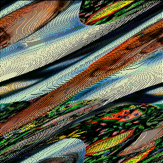
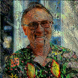
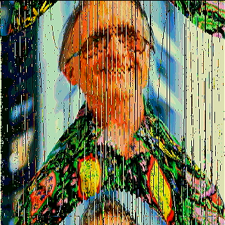
This invertability allows us to leverage the standard map for use in an encryption/decryption scheme. For any value of K, we can encrypt an image by mapping every pixel to a new location [4]. The map's dependency on K (and its chaotic nature for a large K) gives us a two-valued key: K and the number of iterations n. For the third and final part of our project, we implement encryption and decryption mechanisms for 320x320px images in 8-bit color, and use this to encrypt and subsequently decrypt an image of Bruce Land (here, K = 5 and n = 1):
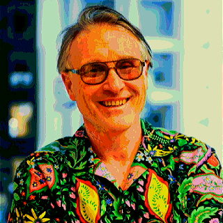
Figure 2: Original Bruce
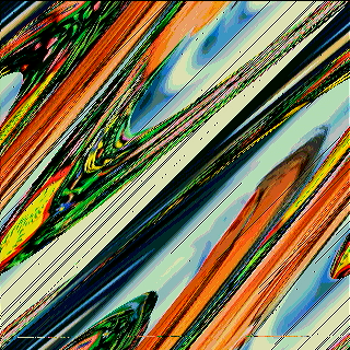
Figure 3: Encrypted Bruce
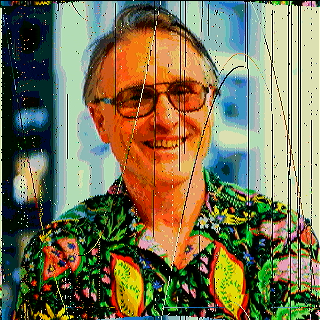
Figure 4: Decrypted Bruce
[top]
High Level Design
Our iterator resides on the FGPA, as this computation can be easily mapped to a state machine. We set initial conditions for the iterator by providing xn and pn, plug in a K, and allow it to run for n iterations. A second state machine in the top-level is attached to a 640x480-element long 8-bit wide M10k block for VGA memory. This one controls the iterator and writes to memory as directed. For our cryptographic demo, we implement an iterator for the inverse of the standard map, divide our memory into 3 individual 320x320 M10k blocks for left, right, and scratch frame buffers, and change our state machine to allow the copying of some buffers to others. Our VGA screen driver is provided by V. Hunter Adams [5].
We use the HPS (ARM Cortex-A9 hard IP) to tug on our top-level state machines through PIO channels. For each of our three demos, we wrote dedicated C programs. Our first two programs give us the freedom to select an input coordinate in real time, select our write data (8-bit color) for our VGA memory blocks, and trigger the iterator. The first contains a thread to poll for mouse inputs, allowing the user to select orbits for a given K. The second automates this process by selecting 100 random points and writing data from a dump PIO channel to CSVs before starting again for another value of K. Our third program copies over a bitmap image to our left and right frame buffers (for use with our cryptographic FPGA program) and sets K and n for the iterator and inverse iterator.
[top]
FPGA Design
Fixed Point
For our project, we settled on using a 10.17 fixed format for the values we would be using in all of our arithmetic and multiplication. In this twos-compliment format, we have a sign bit, 9 bits to represent integers, 17 bits of decimal precision. While we are not blocked from using larger fixed-point formats, we selected it to be forward-looking as it effectively uses DSP cores and promotes future expandability. We selected 9 integer bits since that allows representation up to the integer 511 (29-1), a chaos factor we hoped to use in our cryptography schema that aligned with literature. The remaining 17 bits for the decimal provides enough precision to accurately match against a simulation that uses floating point types, not diverging for an acceptable number of iterations.
Iterator
The basis of our project was our iterator module. This module takes in a clock, reset, trigger, initial conditions, and chaos factor, and outputs the new point and a cycle complete signal. On reset, the iterator loads in the initial conditions and begins to compute the next time step of the standard map (while a clock is provided). When the next iteration has been calculated, it remains in a halted state until the next iteration is trigger. This call-and-response is necessary since our iterator is NOT single cycle and the module that instantiates the iterator shall control the number of requested cycles, and also gives time for the instantiator to save these values.
For the mapping, we perform our calculations in a certain order to reduce the number of cycles taken per iteration in comparison to a naive approach that may calculate the xn+1 and pn+1 independently. Although we presented the condensed form above, the explicit form of the standard map as a causal system is:
pn+1(pn, xn) = pn + K sin(xn)
xn+1(pn, xn) = xn + pn + K sin(xn)
Notice the unnecessary repetition that is eliminated by re-using the newly calculated pn+1 term in the calculation of xn+1. This reduces the number of multiplications and the number of sine table lookups from 2 to 1 per iteration.
Sine Implementation
Since the sine function is not directly synthesizable and performing a Taylor approximation would be a big undertaking for this project, we opted for sine look-up table (LUT). Using all 17 bits of decimal precision would required 217 entries so we opted to use only 12 decimal bits (plus the 3 bits for the integer portion of 2𝜋);
For any xn value that is between 0 and 2𝜋, this LUT takes in the fixed-point values, extract bits 19 to 5 (corresponding to what is described in the previous section), and perform a lookup of that value. This results in an approximation of sin(xn). This enormous table was generated in a Python notebook which will be linked below.
Modulo Operator
We also must recall that these terms are being taken modulo 2𝜋. Our modulo implementation, admittedly, is not the best but does suffice. We implement a repeated addition or subtraction on the initial resultant pn+1 to get it into the appropriate [0, 2𝜋) range. Since pn and xn are always in this range, the number of cycles is dependent on the chaos factor, K.
For K up to 2𝜋, only a single cycle is required. For larger K, additional cycles will be required to subtract it into the appropriate range. This could be solved with additional logic that checks which range the value of pn+1 is within and then subtract the appropriate amount, we did not have critical timing requirements to implement this. Since pn+1 is modulo'd first, the calculation of pn+1 is guaranteed to take a single cycle as it will always be within (-2𝜋, 4𝜋) and it is trivial to perform a single addition or subtraction from here.
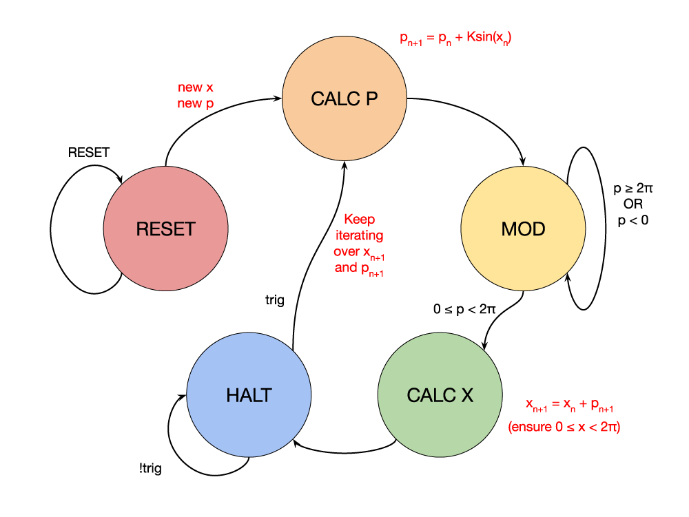
Figure 5: Iterator FSM
All of the same information can be applied to the inverse map, but with an inverted order of operations. Here, we calculate the xn-1 with a single cycle modulo, then calculate pn-1 with a multicycle modulo.
Scalers
Since the standard map operations on the 2𝜋 square, we need to scale these values up to the 480x480 integer grid (or 320x320 grid for the cryptographic demo) for properly displaying on our VGA monitor. For this, we developed 4 additional modules for scaling from 2𝜋→480, 2𝜋→320, 480→2𝜋, and 320→2𝜋. These each contain the hardcoded value of OUT/IN as a parameter in 10.17 format and pass it in as one input to a multiplier. This leaves it up to the compiler as to whether or not to encode the operation as a massive shift-and-add or as a true multiplication.
Interactive Demo
For our interactive demonstration that we hoped to pay homage to the aforementioned StdMap program, we started by instantiating a 307,200 address by 8-bit wide M10k block to serve as our video memory, and also instantiated Hunter Adams' VGA driver. This demo will only utilize the center 480x480 grid but it was easiest to create a "full size" VRAM buffer per the provided driver. We have a master state machine that first drops into a clear screen routine on reset, writing zeros to the entire VRAM buffer as to provide a clean slate for drawing orbits. Once this routine finishes, we drop into a condition where the data being written to the VRAM comes from the output of an iterator.
The drawing of orbits proceeds as follows: a bit in a PIO line signifies when an initial point has been selected and the PIO line that contains the selected 480x480 pixel is valid. These 480-base values are then scaled down to 2𝜋 by the appropriate scaler module and clocked into the iterator. Another bit in a PIO line provides the desired amount of trigger pulses equal to the number of points we wish to plot on a given orbit. On each trigger, we also save out the value from the iterator, scale it back up to the appropriate VRAM buffer, and then cast it to an integer by only grabbing out the integer bits. The color passed in over PIO is used as the write value and the coordinates are used to calculate the appropriate index to the VRAM.
The last hardware supported feature for the demo is frame-saving, where when an appropriate "dump" signal is provided (again over PIO), bypass the VGA driver that typically provides read-addresses into the VRAM. Instead, we are provided addresses over PIO and the resultant read data is sent back to the HPS. When a frame is being dumped, there is a noticeable artifact as we are bypassing the VGA read-address and such the read-data that is still being read by the VGA driver outputs garbled data to the display.
The same HDL is used for the automatic plotter and frame saver, but the controls are all provided for in software and passed as relevant PIO signals.
Cryptographic Demo
For the cryptography section, we define three 320x320 frame buffers to store a base image, and encrypted/decrypted image, and a scratch buffer. We moved from 480x480 to 320x320 due to memory limitations. Instead of using PIO to address into the M10k for frame dumping, we now use it for writing image data to the base frame. This is then copied over to become to the default image for the encryption/decryption frame. This aids in both debugging and demo use as the crypto frame could be reset without intervention of the HPS.
On hardware reset, all the buffers are cleared and we are dropped into the STEADY state. From here, we can move into the WRITE state, where the image is copied in as described earlier, or move into the ENCRYPT or DECRYPT state. The xCRYPT states perform as follows: for each pixel alongside the determined chaos parameter and iteration count, convert the the pixel coordinate from 320-space to 2𝜋-space, run it through the iterator (or inverse iterator) for all N cycles, convert the resultant coordinate from 2𝜋-space back to 320-space, and save the pixel color to the new address in the scratch buffer. After all the pixels have been iterated over and saved into the scratch memory, we then move into the SAVE_SCRATCH state which performs a copy back to the xcrypt buffer.
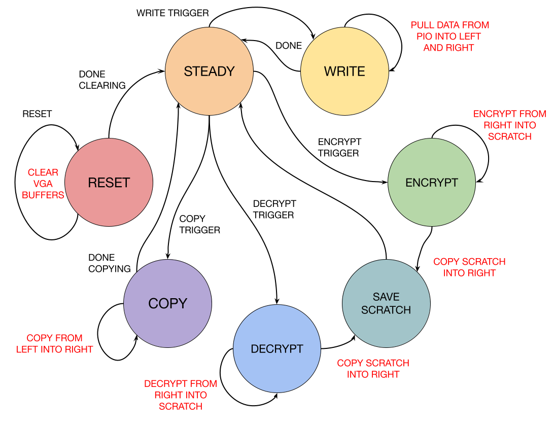
Figure 6: Cryptography FSM
[top]
HPS Design
On the HPS, we primarily use the ARM to control inputs and outputs to our iterator. For our interactive demo, we use a threaded program to poll for mouse inputs and trigger the iterator. For the automated demo, we get rid of the mouse event polling and replace it with an automated nested set of loops to iterate over K and select 100 pseudo-random points. Here, we also add a thread to receive pixel information over PIO and save this data to a csv. For our cryptographic demo, our C program is gutted to only send pixel data to the FPGA for writing images. This program uses command line arguments to set K and n.
Interactive Demo
User Mode
The C program starts by initializing the memory maps associated with the PIO lines, opening the path /dev/input/event0 to allow for reading mouse events, and starting a pthread called trigger_thread. The while loop in main processes data read from the event0 stream and accumulates the mouse's coordinate value since the stream only provides relative updates. The trigger_routine thread only triggers 1000 iterations. It also keeps the mouse coordinates within the confines of a 480x480 grid (offset by 80 to the left to keep coordinates in the center square of the display), and transmits new FPGA control data via PIO. Our following four PIO channels and their used bits are pictured below:

Figure 7: Bitwise PIO Breakdown
Automated Mode
For automated mode, we replace our mouse event input stream with nested loops. An outer while loop increments K and updates its associated PIO channel. An inner for loop selects n starting x and y points and lets the trigger_thread trigger the iterator for 1000 iterations. Note that even though the select x and y input points are determined through the use of rand(), we always reset our random seed for each new K, making these n orbits the same every time. Our color is also deterministic with respect to a given x and y. These choices allow for a really smooth depiction of the evolution of orbits over K in a GIF.
float k = 0.0;
while(1) {
//Begin generating random points
*k_fix_addr = fl2fix(k_float);
for(int i = 0; i < n; i++) {
// Set rand x and y
X_pos = rand() % 480 + 79;
Y_pos = rand() % 480 - 1;
// Deterministic (pseudorandom) color = f(x,y)
color = (48199 * X_track + 12417 * Y_track) % 256;
[RESET ITERATOR HERE]
}
[DUMP VGA BUFFER HERE]
k += 0.025;
}
Given that our HPS-side control mechanism and FPGA-side iterator are NOT synchronized, we must slow the ARM down by calling usleep() frequently. In particular, we sleep for 20μs before selecting a new x,y coordinate and sleep for 2s each time we dump the VGA buffer (though this could be optimized). When flagged, our dump_routine pthread iterates through the 640x480 address space, assigns this address over our P2H_CTRL PIO channel, and receives pixel data over a new DUMP PIO channel. As such, we make the following modifications/additions:

Figure 8: Bitwise PIO Modifications for Demo 2
Cryptographic Demo
Our C program for our cryptographic demo is significantly more simple because all computation lies on the FPGA. This program reads K and n from command line arguments (defaulted to K = 0.5 and n = 1). We use a Python script to turn a .bmp image into a const array of integers corresponding to pixel data. This array is held in a header file and is included at compile time. The C program loops over this array and writes pixel data to a PIO channel. Our P2H_CTRL channel now looks as follows:

Figure 9: Bitwise PIO Modifications for Demo 3
[top]
Testing
Getting the iterator to a complete and working state was more of a challenge that we initially anticipated. We faced several issues from the precision of our sine table to Verilog assuming the signedness of wires that were not explicitly declared. As such, we had to explicitly indicate wires that we needed to be signed.
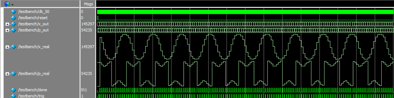
Figure 10: ModelSim testbench of iterator
We first used ModelSim to visually evaluate orbits. Pictured above is an orbit that oscillates without wrapping for x and wraps around for p. Once we validated these orbits visually, we extracted them in tabular format and placed them on a scatter plot:
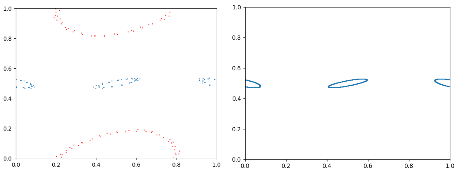
Figure 11: 5-bit vs. 12-bit precision
At this point, the "cloudy" orbits indicated that our sine LUT was not deep enough. We arbitrarily chose a 12-bit precision LUT and wrote a Python script to print a series of assign statements for our case. We had no problem fitting a LUT of this size on the FPGA.
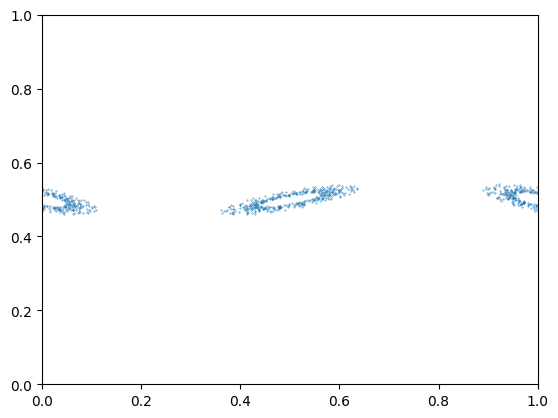
Figure 12: 5-bit sine LUT, wide orbits
After confirming a successful forwarding mapping, we were able to invert the operations as discussed in the FPGA Design section. In ModelSim, we picked arbitrary points, performed N forward mappings, then performed N inverse mappings. We were able to verify our inverse map's properties as the resultant coordinate after both operations was equivalent to the initial coordinate.
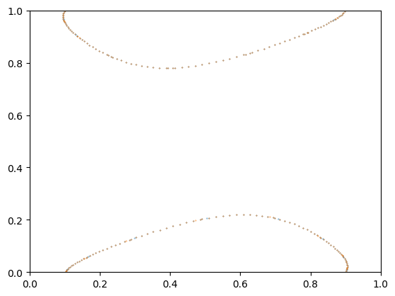
Figure 13: Normal and inverse mapping overlap
In order to verify that our encryption algorithm worked as intended, we wrote the same algorithm in Python with floating point arithmetic. This validated the transforms that we saw on the VGA display and gave us confidence in our state machine design. Pictured below are 320x320 images of Bruce Land in 24-bit color. Here, we set k = 0.5 and N = 1.

Figure 14: 24bit Bruce

Figure 15: FP Encr. Bruce
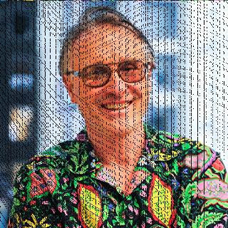
Figure 16: FP Decr. Bruce
[top]
Results
Interactive Demo
Click and drag the pictures to move!
k = 0.0
k = 0.5
k = 1.0

k = 2.0

k = 5.0

k = 15.0
Figure 17: Interactive demo carousel
Note that the dotted lines are not errors, but a result of plotting only a limited number of points across each iteration. For enough iterations, they would become closed and the spottedness is due to only a small increment in the x-direction for each iteration. For low chaos factors, they should form closed loops across the space.
Cryptographic Demo
Click and drag the pictures to move!

k = 0.5, N = 1, encrypted
k = 0.5, N = 2, encrypted
k = 5.0, N = 1, encrypted
k = 50.0, N = 1, encrypted

k = 0.5, N = 1, decrypted
k = 0.5, N = 2, decrypted
k = 5.0, N = 1, decrypted
k = 50.0, N = 1, decrypted
Figure 18: Cryptography carousel
You will notice that there are many black pixels and strange artifacts that occur in the encrypted and decrypted pictures. This is due to the loss of precision when moving in and out of 2𝜋-space, causing rounding issues. If the full fixed-point data was saved, a lossless decryption would be possible but when scaling up to 320-space, not all resultant points align with pixel space. Many pixels do end up overlapping with other drawn pixels, causing color-based artifacts and then black spaces where things did not perfectly map. Some of this is still evident in our floating point computations, as shown in the Testing section.
If time allowed, we would investigate the warping that occurs in images processed with extremely large chaos factors, as this was not something we saw occur in floating point simulation or in our literature review. This could also be solved by adapting the mapping to the 320-space rather than converting back and forth between the spaces.
[top]
Conclusions
Ultimately, we were able to succesfully implement an iterator for Chirikov's Standard Map in synthesizable Verilog on the DE1-SoC and apply this iterator towards a proof of concept for encrypting and decrypting images. We succesfully compared our work against Python scripts and performed a qualitative analysis of our cryptography. Our first project component allows for point-and-click interaction, and this serves as a good introduction to chaos theory for students. Our second project component automates the orbit-projection process and extracts pixel data. Our third and final project component leverages the standard map for use in a cryptography program.
There are many ways that this project could be extended given more time. In our implementation, we only instantiate two iterators at most (one for each of encryption and decryption). One could attempt to maximize hardware usage by leveraging many iterators in parallel. One could also reduce our modulo operation to a single cycle, greatly reducing computation time for large values of K. One could also attempt to use our encryption/decryption methods on a larger image and compare results of image loss. One could build on our encryption scheme to apply some "statistical smoothing" over the image, which would make the encrypted image resistant to statistical analysis attacks.
While the theory behind Chirikov's Standard Map is vast, it is nevertheless fascinating for students like ourselves. One could spend many years learning about the map, its integrability, manifolds, symmetrics and Kolmogorov-Arnold-Moser (KAM) theory. For us, the endless wealth of information behind our work is what makes our first foray into the standard map so special.
[top]
Appendix A: Permissions
The group approves this report for inclusion on the course website.
The group approves the video for inclusion on the course YouTube channel.
[top]
Appendix B: Video Demo
[top]
Appendix C: Program Listings
Scripts:
Base Files:
Demo 1: Interactive Map Plotter
Demo 2: Orbit Phases
Demo 3: Cryptography
[top]
Appendix D: Work Distribution
Proposal
Our project proposal was completed together in-person before a scheduled lab session.
Week 1
Preliminary work for our iterator was completed together in our scheduled lab time. Together, we simulated our iterator in ModelSim, extracted outputs in tabular format for a singular orbit, and plotted them with Python.
Week 2
Together, we began integrating our system with the DE1. In Quartus, we added PIO lines for HPS/FPGA communication. Harris wrote a quick top-level state machine to tug on the iterator and clear the VGA buffer. Max wrote the preliminary C program to allow for user input.
Week 3
Harris spent some time debugging the iterator back in ModelSim. He successfully resolved a bug associated with black pixels on the top-right corner of the screen. Max spent some time modifying the C program to automatically plot random orbits and loop over increasing values of K. Both parties worked on the VGA dump mechanism on the FPGA and HPS, as well as the associated Python scripts for generating a GIF from a bunch of CSV files.
Week 4
Harris derived the inverse standard map equations and developed the inverse iterator. Both parties wrote the state machine Verilog together. Max spend some time individually debugging the state machine. Max and Harris reunited to continue debugging, fixing and finishing the cryptographic demo.
Report
Website design work was completed collaboratively. Harris made the banner and edited photos while Max made FSM diagrams and had some fun with CSS styling. Max wrote the introduction, High Level Design and Conclusion sections. Harris wrote the FPGA Design and Results sections. Both parties worked on the HPS design and Testing sections and the appendices.
[top]
References
- B.V.Chirikov, "Research concerning the theory of nonlinear resonance and stochasticity", Preprint N 267, Institute of Nuclear Physics, Novosibirsk (1969) (Engl. Trans., CERN Trans. 71-40 (1971))
- X Chirikov Chaos Commandments
- J. D. Meiss, ‘Visual explorations of dynamics: The standard map’, Pramana, vol. 70, no. 6, pp. 965–988, Jun. 2008.
- Y. Zhang and D. Xiao, ‘Double optical image encryption using discrete Chirikov standard map and chaos-based fractional random transform’, Optics and Lasers in Engineering, vol. 51, no. 4, pp. 472–480, 2013.
- V. Adams. “VGA Driver in Verilog.” ECE 5760.
- C. Antonellis. “freezeframe.js.” GitHub.
- P. Grzybek. “Siema.” GitHub.
[top]
Special Thanks
We would like to thank Hunter Adams and Bruce Land for their unwavering support throughout our project. Special thanks to Pickles!
We would also like to thank Jeff Yates, Tom Gowing, and Kerran Flanagan for their HTML and CSS source code and design inspiration.