|
STINKJET: The Valve-Controlled Smell Generator
Microcontoller Board
 The microcontroller
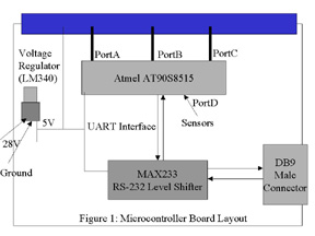
board provides an interface between the user (via a PC) and the relays and
sensors. The layout of the board is shown in figure 1. The actual board,
which attaches to the relay board via an edge connector, was created using
the ExpressPCB software. The layout
file is available for download. The microcontroller
board provides an interface between the user (via a PC) and the relays and
sensors. The layout of the board is shown in figure 1. The actual board,
which attaches to the relay board via an edge connector, was created using
the ExpressPCB software. The layout
file is available for download.
Microcontroller
The Atmel AT90S8515 contains 8Kb of FLASH program memory. It is clocked via a 4 MHz crystal on the board. The CPU provides 32 user programmable I/O pins. Two of those pins, PortD0 and PortD1, act as the RS232 transmit and receive lines. Three pins, PortD5 through PortD7, connect to the sensors. 24 of the remaining pins, PortA, PortB, and PortC, control the relays via the edge connector. Table 1 summarizes the pin usage.
| Table 1: Microcontroller Pin Usage |
| Pin | Function |
|---|
| PortA | Relays 0 through 7 |
| PortB | Relays 8 through 15 |
| PortC | Relays 16 through 23 |
| PortD0/D1 | UART Transmit and Receive |
| PortD7 | Sensor 0 |
| PortD6 | Sensor 1 |
| PortD5 | Sensor 2 |
Power Supply
The only power supply in the system is the 28VDC source for the relays. This power is fed into an LM340 Voltage Regulator from National Semiconductor, which outputs a 5VDC supply for the digital hardware. This 5VDC line supplies the microcontroller, level shifter, relay board, and sensor box.
Level Shifter and RS-232 Hardware
The RS-232 standard used by the PC serial port used +10V to signify digital 0 and -10V to indicate digital 1. Because the Atmel CPU only puts out 0 and 5V, level shifting is required for use with the PC. The chosen component is the Maxim MAX233. Unlike related parts, this component requires no additional capacitors, saving on board space. It contains internal charge pumps for generating the +10V and -10V and requires only a 5V supply to run. The MAX233 connects to a male DB9 connector for the PC interface. Note that a straight-through serial cable must be used.
|