|
STINKJET: The Valve-Controlled Smell Generator
Physical Setup
Figure 1 below illustrates the basic structure of the system. The following a description of each basic component.
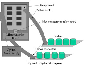
Valves
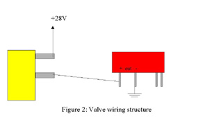
The valves are arranged on two plexiglass sheets (nine to a sheet). They require a voltage of about 24 VDC to open. Each row is wired through a screw terminal. The bottom connectors of each of the valves are shorted together and linked through the screw terminal to the +28 VDC supply. The top terminal of each valve is connected through the terminal block to the positve output of a relay on the board. The negative terminal of each relay is linked to ground. When the relay is open, the top terminal of the valve floats high. When the relay is closed, that terminal is shorted to ground and the valve opens. Figure 2 illustrates this structure.
Relay Board
The relay board has room for 24 Potter-Brumfield ODCM-5 optical relays. 18 of the relays are currently in use, arranged in two columns of 9. Each column switches one plexiglass row of valves. The board has a male edge connector on the bottom with 25 pins. Pin 1 is the +5 VDC power input. Pins 2 through 25 switch the relays. Pin 2 controls relay 0; pin 3 controls relay 1, etc. The relays use negative logic, meaning they close in response to a logic 0 input. Note also that in order to use pin 1 to supply power, a fuse must be installed on the board.
Microcontroller Board
The controller board, described in more detail in the Microcontroller Hardware section, connects to the relay board via a female edge connector. It is powered by the 28 VDC source and supplies 5 VDC to the relay board and sensor box.
Sensors
Each of the three sensors consists of an infrared LED/sensor pair. They each form a beam across a plastic nozzle into which the rat can stick its nose. The electronics for the sensor are housed within a plastic enclosure. Each sensor circuit contains an LM311 comparator from National Semiconductor. The voltage from the sensor is compared against a threshould set by a voltage divider. The threshold is adjustable via a potentiometer on the outside of the box. The comparator output, which is logic 0 when the sensor is broken, connects to the microcontroller board.
|