Introduction
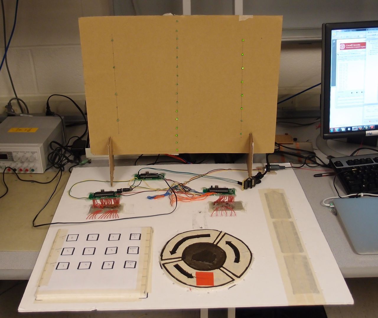
ProxiMIDI is a MIDI code generator, that takes its inputs from a user using Atmel’s Capacitive touch and Proximity technology. It can generate sound signals for 4 notes of 3 instruments and vary the tempo, volume and sound depending upon the proximity inputs. The signals generated from ProxiMIDI can be connected to any MIDI player (example - a MIDI keyboard or a Computer) to generate sound.
The objective of this project is to gain experience and skill in designing Capacitive touch and Proximity sensors based on Atmel’s QTouch technology along with using that in an application to demonstrate its usability, in doing so, we have focused on a whole array of sensors possible by using Qtouch technology. Apart from the more prominently used Buttons, Sliders and Wheels, we have implemented them in a proximity sensing role - allowing the user to control without touching. Our project also focuses on various MIDI codes and how they can be successfully generated using an 8 Bit microcontroller.
High Level Design
Design of the System
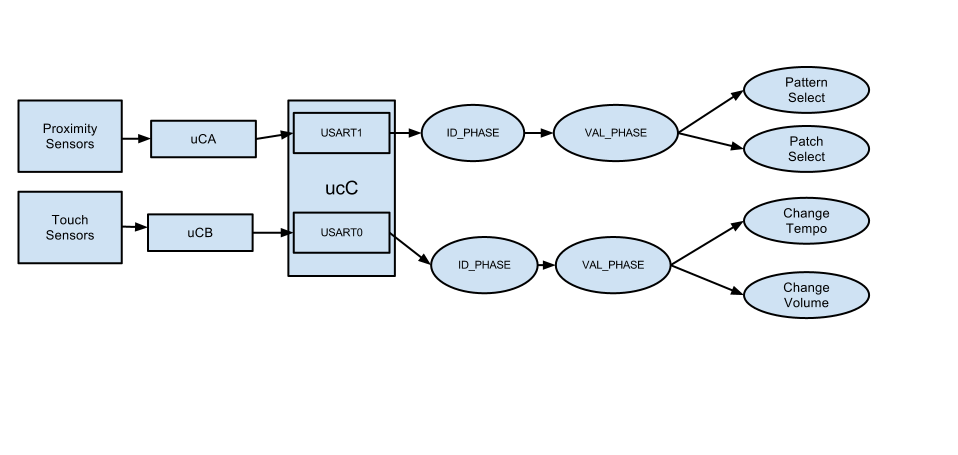
The system consists of 3 microcontrollers each serving a role in the project. The microcontrollers have been named A, B and C for convenience.
Microcontroller A (µcA), controls the touch keypad. It detects the touch inputs on a keypad and reports them through serial connection to microcontroller C. It controls a total of 12 buttons, arranged in a 4 x 3 matrix. This setup, using QTouch technology, uses two pins per touch button channel. Thereby, consuming 24 pins of the microcontroller to implement 12 buttons.
Microcontroller B (µcB), controls the proximity sensing, It detects, measures and transforms the proximity readings from the proximity pads into segmented data that can be utilized by the microcontroller C. Microcontroller B also controls the LEDs that are used to denote the state of the proximity input from the user. The movement on the circular slider is detected as a volume signal, with values ranging between 0 and 255. Similarly, for the linear slider, the value inputs vary between 0 and 255 depending upon the signal input.
Microcontroller C (µcC), takes the inputs from µcA and µcB, and generates MIDI signals. The MIDI signals are generated depending upon values from the µcA and µcB, which includes the instrument and the sound selection, tempo and volume selection.
Detailed Explanations:
µcA:
This microcontroller uses Atmel® Qtouch® technology to implement 12 touch buttons. The buttons work by measuring the capacitance of a plate.The system, first, charges the capacitor and the plate and then discharges the capacitor. In this process, records the time utilized in completing few such cycles. Presence of any finger near the plate (button) changes the capacitance of the system being measured. This results in a changed charging / discharging time which is reported as a touch to the user.
µcB:
This microcontroller implements proximity sensing using Atmel Qtouch. We used enlarged button areas and higher capacitance values to implement the sensing techniques.
Higher area enables sensing at a larger distance due to higher electric field volume interacting with the sensor.
Another important function fulfilled by this microcontrollers is that it controls 24 LEDs, 16 for Tempo and 8 for Volume depending upon user inputs. This is done using 4:16 multiplexing ICs which enable an accurate display of status of the system using LEDs.
µcC:
This microcontroller receives the volume and tempo data from µcB and note and channel data from µcA over serial communication lines. It processes this data into MIDI commands that are transmitted from port C0 to a MIDI plug.
Amtel Qtouch Explained
QTouch is a capacitive touch sensing technology from Atmel. It works on the charge transfer principle that enables measuring the capacitance of the sensor by continuous charging and discharging. The sensor is an electrode of copper, aluminum or any other conducting material. Each sensor is connected to two channels or I/O port pins through an RC network as shown :
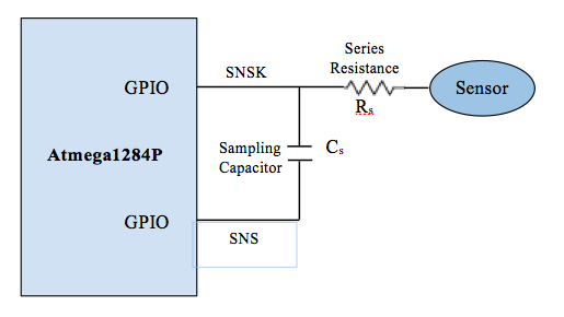
The sampling capacitor is supplied with voltage pulses and its capacitance is determined by using a measuring circuit provided by the QTouch Library API.
When a finger is brought close to the sensor, it induces charge into the sensor and as a result, the capacitance of the sensor varies. The sampling capacitor hence takes lesser time to charge or discharge.
The number of charge cycles it takes for the capacitance to charge without a touch is called reference level and the number of charge cycles it takes for it to charge with a touch is called the signal level. When the signal value differs from the reference value by a certain ‘delta’, a counter is incremented. When the difference is greater than delta for ‘n’ counts given by a parameter called detect integration, the sensor is detected as touched.
The SNS line in the above figure is the Sense Line used to charge the capacitor through the charging pulses. The SNSK line is the Sense Key Line used to discharge the capacitor.The Series Resistance Rs Serves to remove the chances of an electric discharge on the MCU. Atmel’s documentation states the typical value as 1 Kilo Ohms, which worked very well for us. It should be noted that the Touch functionality also worked perfectly without this resistor, but it was put in interest of safety.
The Atmel QTouch library provides the required functions to implement a key, slider and rotor. A rotor and slider require 3 channels each i.e 3 sensing capacitors and total 6 MCU pins each. QTouch library also provides for adjacent key suppression (AKS) which enables to suppress false adjacent key detections since a finger near a key slightly changes the capacitance of adjacent sensors as well.
QTouch technology is said to be highly robust, reliable and flexible. Compared to resistive touch, this technology has very low power consumption and better SNR
Amtel QMatrix Explained
QMatrix is a capacitive touch detection technology from Atmel. This method uses two electrodes to implement every key and falls under the category of “Mutual Capacitance” sensors, since each sensor induces field onto itself.
For simpler explanation, let us label the parts of the electrode X and Y. The X forms the ‘driving’ electrode, i.e. X receives a varying - sinusoidal like signal from the microcontroller. This signal is induced upon to the Y electrode, which senses the incoming signal. The strength of the signal varies the dielectric medium separating both X and Y electrodes. When a finger is introduced in between or near theses electrodes, the electric field associated between both the electrodes changes, causing a variation in the received signal. This data can be used to sense a touch.
According to the manufacturer:
“ QMatrix circuits offer tremendous signal-to-noise ratios, high levels of immunity to moisture films, extreme levels of temperature stability, superb low power characteristics, ease of wiring, and small IC package sizes for a given key count, For these reasons, QMatrix circuits are highly prized for automotive, kitchen appliance, and mobile applications. ”
The QMatrix technology is optimized for a low pin count operation, such that, only 9 pins of the microcontroller are needed to setup a 16 key keypad.
The technology can also be used for Proximity sensing, but is reported to have lower range than a QTouch proximity sensor.
Qtouch and QMatrix compared
| Technology Name | QTouch | QMatrix |
|---|---|---|
| Technology Type | Self Capacitance | Mutual Capacitance |
| Technology Principle | Electric field lines projected into free space to couple with objects | Electric field lines projected from the X electrode to the Y electrode |
| Pin Requirements | Two pins per key | 8 + 1 pins for 4x4 keypad |
| Circuit Design | Simple Circuit Design, does not require PCB fabrication. | Complicated circuit design, requires PCB manufacturing. |
MIDI format
MIDI 1.0 is a communications standard developed for digital musicians for the transmission of musical information. A MIDI transfer involves a serial protocol which sends packets at a baud rate of 31.25 kilohertz, requiring an accuracy of 1%. Messages are sent eight bits at a time, utilizing one stop bit for synchronization purposes. Messages are sent between MIDI compatible devices to signal note generation, instrument selection, and various controllers such as the modification of tempo and volume.
Each command consists of a command byte and some number of data bytes. A command byte consists of a 4 bit command identifier, and a 4 bit channel number. The command identifier chooses actions such as start and stop, while they channel selector chooses a channel to apply the command to. A channel is equated to an instrument in MIDI 1.0. Instrument patches can be applied to channels and notes played on that channel will play the corresponding note on the chosen instrument. This scheme allows for up to 16 instruments to be controlled simultaneously, allowing for the composition of music. While MIDI 1.0 only supports 16 channels, later versions expanded upon this limit.
Notes are mapped to their frequency values, and the 128 of them are arranged by octave for selection via 12 tone equal temperament mapping, similar to a grand piano. Tables of note values can be found online due to their standardization. Volume is controlled by sending a value with each note, with a 0 corresponding to mute and 127 corresponding to the maximum value the receiver can produce.
While there are many messages specified by MIDI 1.0., our goal for the project was to start and stop various notes simultaneously, so we chose a set a commands which could accomplish this. By following the standards of MIDI, however, these commands can be sent to any MIDI device and provides ProxiMIDI with modularity and compatibility with existing musical systems.
An overview of MIDI commands supported by ProxiMIDI is listed below:
Note On:
| Byte 1 | Byte 2 | Byte 3 |
|---|---|---|
| [Command][Channel] | Note[0-127] | Volume[0-127] |
| [0x9][0x0 - 0xA] | [0x00 - 0x7F] | [0x00 - 0x7F] |
This three byte command instructs a note to begin playing on the specific channel(0-A) at a specified volume. 0x90 0x30 0xFF would instruct a synthesizer to play Middle C at maximum volume on Channel 1.
Note Off:
This three byte command instructs a note to stop playing on the specific channel(0-A) at a specified velocity. This three byte command instructs a note to begin playing on the specific channel(0-A) at a specified velocity. 0x91 0x30 0x7F would instruct a synthesizer to stop the playing Middle C at the fastest possible rate on channel 2.
| Byte 1 | Byte 2 | Byte 3 |
|---|---|---|
| [Command][Channel] | Note[0-127] | Volume[0-127] |
| [0x8][0x0 - 0xA] | [0x00 - 0x7F] | [0x00 - 0x7F] |
Patch Change:
This sets the current patch for this channel. The first byte identifies the command(0x3), and the channel. First data byte is the desired patch, designated by the MIDI standard.
| Byte 1 | Byte 2 |
|---|---|
| [Command][Channel] | Patch |
| [0x8][0x0 - 0xA] | [0x00 - 0x7F] |
Patches:
Patches are specified by the General Midi 1.0 Standard, which contains 128 instrument types for use in synthesis. The following selections were used for patching.
| Channel | Instument | Patch Code |
|---|---|---|
| 1 | Gt. Harmonics | 32 |
| Syn. Strings 1 | 51 | |
| 2 | Slow Strings | 50 |
| Piano 1 | 1 | |
| Pickled Bs. | 35 | |
| Clean Gt. | 28 | |
| 3 | Synth Drum | 119 |
| Steel Drums | 115 | |
| Tinkle Bell | 121 | |
Serial Communication between Microcontrollers
Since communication is performed via USART, a protocol was developed to allow for the the MIDI generating µcC to receive ID and value packets from the sensor micro controllers. The protocol requires messages to be in a two byte format. The first byte is the ID of the sensor which has made a measurement. Each time a sensor records a new value which is different from its previous value, it sends the ID and value over USART to µcC. Each USART is configured at a baud rate of 9600, with 8 bit length, one stop bit and no parity bit. The two byte messages required µcC to keep track of whether or not a given byte should be interpreted as an ID or a Value, which is accomplished by state machine logic. USART0 on µcC reads the button presses, while USART1 is used to periodically receive proximity sensor values. Each USART has its own ISR and state machines.
Hardware Design & Implementation top
Initially, a PCB based design was created and PCBs were ordered which contained all three microcontrollers and the keypad button. The units received were unable to communicate with our programmer, and thus a handbuilt design was created which contained the same functionality.
PCB Design:
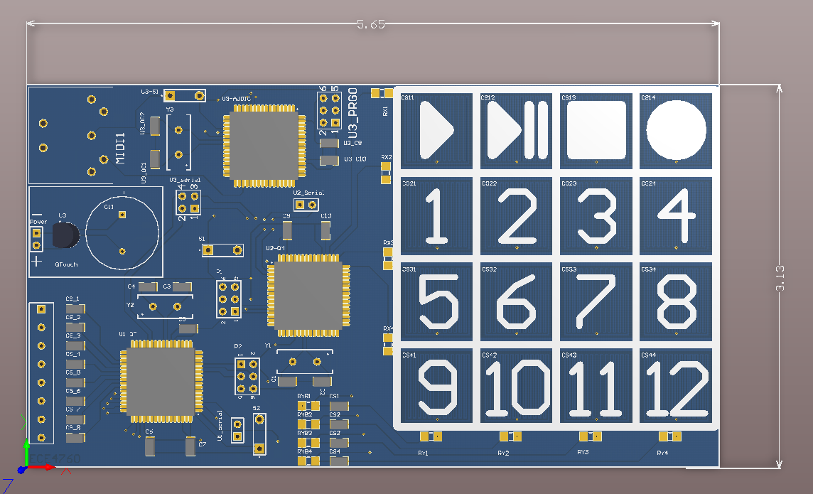
Link to full schematic here:
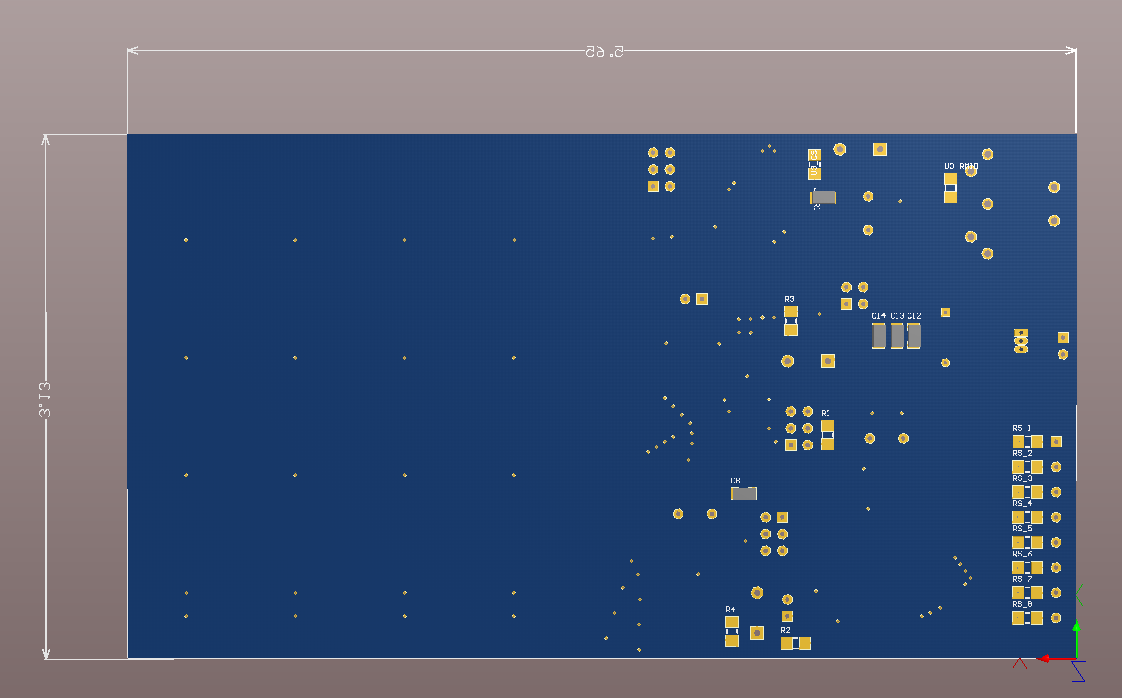
Board Design:
Link to full schematic here:
MIDI output hardware
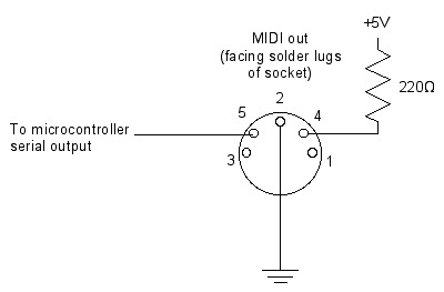
MIDI is a current-based system, measuring its presence or a lack thereof to transmit information. The bus is keep at a high value of 5 amps when not in use. MIDI output is accomplished on µcC by holding PINC0 high and lowering each time a message bit is read as high during output ISR.
Multiplexers for LED lighting
We used CD4514BE ICs to implement the LED lighting. These are 4 Bit Latch 4-to-16 line decoders.
The chip has 4 data lines to select one of the 16 pins to output to. It follows the following configuration to output.
The STROBE Pin requires a transition from LOW to HIGH to enable transmission of the data lines. (represented by T below)
The chip will transmit data only when INHIBIT pin is pulled LOW.
Each of the Spins was linked to an LED through a 330 Ohm resistor.
STROBE
INHIBIT
DATA1
DATA2
DATA3
DATA4
OUTPUT
T
LOW
LOW
LOW
LOW
LOW
S0
T
LOW
LOW
LOW
LOW
HIGH
S1
T
LOW
LOW
LOW
HIGH
LOW
S2
T
LOW
LOW
LOW
HIGH
HIGH
S3
T
LOW
LOW
HIGH
LOW
LOW
S4
T
LOW
LOW
HIGH
LOW
HIGH
S5
T
LOW
LOW
HIGH
HIGH
LOW
S6
T
LOW
LOW
HIGH
HIGH
HIGH
S7
T
LOW
HIGH
LOW
LOW
LOW
S8
T
LOW
HIGH
LOW
LOW
HIGH
S9
T
LOW
HIGH
LOW
HIGH
LOW
S10
T
LOW
HIGH
LOW
HIGH
HIGH
S11
T
LOW
HIGH
HIGH
LOW
LOW
S12
T
LOW
HIGH
HIGH
LOW
HIGH
S13
T
LOW
HIGH
HIGH
HIGH
LOW
S14
T
LOW
HIGH
HIGH
HIGH
HIGH
S15
Software Design & Implementation top
QTouch implementation
As mentioned above, every sensor requires two port pins for implementation. In this project, we use a 3x4 keypad for selecting the MIDI patches and patterns, one wheel for controlling the tempo and one slider for controlling the volume of the MIDI. Since each sensor needs to two channels to operate, the keypad requires 24 port pins and each of the Rotor and Slider require 6 port pins. µCA is used to implement the touch sensing of the keypad and µCB is used to implement the proximity sensing of rotor and slider.
The basic implementation of keypad and rotor/slider is similar. We used the QTouch library functions to initialize the sensors, set the detection parameters and measure data. System initialization includes setting the system clock, disabling the JTAG pins and disabling the pull-ups (using assembly or using the fuses). In this case, we used assembly language programming. The system clock is set to run at half the external crystal oscillator frequency i.e at 8MHz. The function init_system() does this task.
The touch measurements have to be made periodically for which we used a timer ISR executing at 50 milliseconds. Every 50 milliseconds, a flag is set indicating that it is time to measure touch. The timer initialization is done using init_timer_isr() function. After the timer and system are initialized, the touch sensors need to be configured. For this, the studio masks indicating the connections to Port pins are set up using the QTouch Studio Pin Configuration Wizard. The sensors are set up as keys or rotors or sliders as desired using the config_sensors(). This function uses the QTouch predefined public functions :
1) qt_enable_key (channel_t channel, aks_group_t aks_group, threshold_t detect_threshold, hysteresis_t detect_hyseteresis)
2) qt_enable_rotor (channel_t from_channel, channel_t to_channel, aks_group_t aks_group, threshold_t detect_threshold, hysteresis_t detect_hyseteresis, resolution_t angle_resolution,uint8_t angle_hysteresis)
3) qt_enable_slider (channel_t from_channel, channel_t to_channel, aks_group_t aks_group, threshold_t detect_threshold,hysteresis_t detect_hyseteresis,resolution_t position_resolution, uint8_t position_hysteresis)
The default values we chose were 2 counts for the detect_threshold with a hysteresis of 6.25% and zero position/angle hysteresis. The position resolution is selected to be 8-bits and hence the sensor changes value from 0 to 255. The parameters recalibration delay, drift values also have to be set. This is done in function qt_set_parameters(). In this case we set the sensors to have no recalibration process.
Each time the user wants to scan the sensors and check if they are in detect, the user has to use the function touch_measure() which calls the QTouch library data structure qt_measure_sensors which updates the status flags indicating whether there has been a change in the signal level levels of any sensor, if the sensor requires to be checked repeatedly etc. The user uses these status flags for further implementation. In this case, if the QT_LIB_BURST_AGAIN flag is set to 1, then the qt_measure_sensors is called again to update the flags. This process continues till the burst again flag is reset. The function touch_measure() is called inside an infinite loop to continuously scan the sensors.
After this point, we define 2 macros to detect the key touch or proximity sensing of rotor/slider.
Keypad Implementation(µcA):
We used all pins of Port A,B and 4 pins each of Port C and D for 12 channels corresponding to 12 keys. Each sensor is labeled by the SENSOR_NUMBER from 0-11. In order to check which key has been pressed, we use the macro GET_SENSOR_STATE(SENSOR_NUMBER) as :
#define GET_SENSOR_STATE(SENSOR_NUMBER) qt_measure_data.qt_touch_status.sensor_states[(SENSOR_NUMBER/8)] & (1 << (SENSOR_NUMBER % 8))
where qt_measure_data is a QTouch Library defined data structure that has three fields – channel_signals[], reference_signals[] and qt_touch_status[]. For a key press, we only need to detect if the status has changed from 0 [No detect] to 1[Detect]. Hence, the above macro accomplishes the task of checking if a particular sensor/key has been touched. A number of ‘if’ statements checking the status of each of the sensors are written and corresponding sensor number transmitted to the MIDI control MCU through a serial UART.
In order to ensure that sensor number is not transmitted repeatedly when a user holds down one key for a long time, we check if the previous key press was the same as the current. We transmit data only when it is not the same. In order to account for pressing the same key twice, for example – 1;1, we check if at any point none of the sensors are in detect. In this case, the SENSOR NUMBER is reset and multiple presses of a single key can be effectively detected.
Rotor/Slider Implementation (µcB)
We used Port A and B for 6 channels required by one wheel and one slider. The wheel controls the tempo and slider controls the volume of the MIDI. In addition to detecting which sensor value has changed using GET_SENSOR_STATE(SENSOR NUMBER), we have to get the position/angle of the user’s hand on the proximity sensor. This is achieved using another macro defined as follows :
#define GET_ROTOR_SLIDER_POSITION(ROTOR_SLIDER_NUMBER) qt_measure_data.qt_touch_status.rotor_slider_values[ROTOR_SLIDER_NUMBER]
As mentioned above, in addition to sensor_states[], the data structure qt_touch_status has another field called rotor_slider_values[ROTOR_SLIDER_NUMBER]. This returns the position/angle of the detection on the slider/rotor respectively. The rotor_slider_number is initialized depending on the order in which the rotor and slider were defined.
In order to transmit this data from the rotor and slider to the MIDI MCU, we send alternating tempo and volume values at regular intervals of 1 second in order to not overflow the receive buffer of the MIDI control MCU. For the MIDI control MCU to detect from which sensor the value came from i.e, whether it was volume or tempo change, in addition to the raw values we transmit an ID indicating whether the data that follows is a tempo variable or a volume variable. These IDs can be defined by the user to any values they desire.
MIDI Generation (µcC)
Due to the frequency requirement of a transfer speed of 31.25 kilohertz, an ISR is utilized on µcC to raise and lower output pin C0 in order to transfer data to the MIDI receiver. Since µcC is clocked at 16 Megahertz, a prescaler value of 8 lowers the clock to 2 Megahertz. An overflow counter OCR2A is set to 63, further dividing the clock of the ISR so that every 64 counter increments the MIDI handling code is run, which works out to be exactly at the rate of 31.25 kilohertz, satisfying the 1% accuracy requirement of the MIDI protocol.
Microcontroller inter communication protocol
Since communication is performed via USART, a protocol was developed to allow for the the MIDI generating µcC to receive ID and value packets from the sensor micro controllers. The protocol requires messages to be in a two byte format. The first byte is the ID of the sensor which has made a measurement.
Byte 1
Byte 2
Sensor ID
Value
The proximity sensors periodically send their IDs and values via USART1 to ucC while the touch sensors record presses, sending messages over USART0. Each USART is configured at a baud rate of 9600, with 8 bit length, one stop bit and no parity bit. The two byte messages required µcC to keep track of whether or not a given byte should be interpreted as an ID or a Value, which is accomplished by state machine logic. The first received byte is interpreted as an ID, whose value is recorded. The next byte corresponds to the value , after which an action can be taken if a valid ID has been recorded. The parameters modified by the sensor messages in turn modify the messages outputted by the MIDI sequencer.
Note Generation
As the ProxiMIDI controller generates music, a scheme was designed to periodically send MIDI messages to a synthesizer in order to produce music. This was accomplished by creating patterns stored on µcC, which are sampled at rate controlled by tempo and whose values are used to send MIDI messages corresponding to the raising or lowering of notes. Tempo is controlled by modifying a software defined counter which controller the sampling function. Lowering the counter value causes the function to be run more often, increasing the tempo.
Sound generation
To generate the patterns of MIDI notes for musical composition, the arrays are read at a rate controlled by the tempo set by the circular proximity sensor. It samples the arrays which contain quarter note values and turns the notes on if they are valid notes. A sustain value is used to signify that a value should not be turned off a half or whole note, which prevents the controller from turning the note off at the beginning of the next sampling of the arrays. Channels 1 and 3 are composed of chords, which are sampled three at a time. The MIDION messages are sent using the volume parameter set by the proximity slider. Each time a patch change request is received from the sensors, ProxMIDI sends a patch change message to switch to a new instrument. This scheme allows for pattern changes and various instrument combinations.
Patch Selection
Patches were able to be changed by receiving button presses corresponding to a desired patch change and using a circular buffer of the instuments listed above to send PATCHCHANGE messages to the MIDI synthesizer.
Conclusions
Expectations Met / Not Met
The project met most of the expectations and design parameters.
Some of the difficulties encountered dealt with the sensitivity of proximity system to individual charged bodies. Some of the students wearing silk/wool garments were statically charged. This lead to unexpected behavior from the proximity system - including random increase and decrease in reading and proximity sensing ranges, but for 90% of the cases, the sensor worked perfectly fine.
The software is designed to calibrate on startup and expects the user to not be around when starting up. The calibration takes place one to two seconds after starting up. If the user is present during calibration, the electric field generated by the user is taken as the default measurement - or the baseline. Any future readings are compared with this baseline to determine if a touch has been detected or not, resulting in false readings.
Presence of any current carrying conductor also has similar effects on the proximity sensor - placing a switching LED or a USART cable near a proximity sensor causes it to record absurd values - possibly due to the electric field generated by the switching currents in the wire.
Conformed Standards
ProxiMidi conforms to the GM Midi 1.0 standard, being tested on a laptop computer using a EMU XMIDI USB MIDI interface and a standard electronic keyboard which accepts MIDI inputs. Both were able to receive commands to start and stop notes as well as changing patches on multiple channels.
We are not aware of any standards regarding capacitive and proximity sensing, but since it follows the standard Atmel ® QTouch protocol, it should conform to any standards included in the protocol.
Ethical Considerations
The project is safe to use, it runs on a transformer based power supply (typically 9 Volts) and further drops it to 5 Volts before powering the microcontrollers and the test circuits.
No part of this system is hazardous to touch. We have electrically insulated the entire project to avoid any electrostatic discharge from the user on to the board.
The system does generate a minor EMI (Electro Magnetic Interference) due to the charging - discharging of the capacitor, but its range is limited and effect negligible. On the other hand, the system is very sensitive to EMI, and does generate false readings in presence of strong EMI. We used decoupling capacitors at various locations to reduce the effect of EMI on sensor measurements.
Intellectual Property Considerations and Legal Considerations
QTouch and QMatrix:
The QTouch and QMatrix brands are owned by Atmel, and the code generated by the code composer studio uses Atmel’s proprietary technology. Users are allowed to use the code without any warranties. Atmel requires the copyright notice to not be removed from the code, which we followed.
MIDI legal considerations:
The MIDI protocol is freely available on the internet as it is a a communications standard. MIDI technology was standardized by a panel of music industry representatives, and is maintained by the MIDI Manufacturers Association (MMA).
We did not violate any intellectual property rights in developing this project. All specifications for the project were designed and implemented by us. We wrote most of the code, with no violation of any patents. We referred to Prof. Bruce’s code on UART initialization and functionality to implement the serial communication between the 3 microcontrollers used. We used the GCC QTouch library and API to implement capacitive sensing. Portions of the ISR which serialized MIDI data from the Glove Midi Controller project were used to sent messages to the audio device. The simplicity of operations allowed for us to make improvements on the design and create more complex musical patterns. We do not plan to get patents for this project as there a number of QTOUCH based devices in the market today.
Appendices top
A. Parts List and Costs
Category
Item
Vendor
Unit Cost
Quantity
Total Cost
Electronics
Custom PC Board
ECE 4760 Lab
$4.00
3
$12.00
ATMega1284
ECE 4760 Lab
$5.00
3
$15.00
CD4514BE 4 to 16 Latch/Decoder
ECE 4760 Lab
$0.00
2
$0.00
9V Power Supply
ECE 4760 Lab
$5.00
1
$5.00
Green LED
ECE 4760 Lab
#0.00
28
$0.00
Connections
Solder Board (6 inch)
ECE 4760 Lab
$2.50
2
$5.00
Header Pins
ECE 4760 Lab
$0.05
34
$1.70
Wire
ECE 4760 Lab
$0.00
N.A.
$0.00
Midi Connector
Digikey
$1.25
4
$5.00
ECE 4760 Lab
$0.00
8
$0.00
Physical Structures
Foam Board
Cornell Store
$5.00
1
$5.00
40nF Capacitors
ECE 4760 Lab
$0.00
7
0.00
22nF Capacitors
ECE 4760 Lab
$0.00
12
0.00
1k Ohm Resistors
ECE 4760 Lab
$0.00
20
0.00
330 Ohm Resistors
ECE 4760 Lab
$0.00
32
0.00
Copper Tape and Aluminum Foil
ECE 4760 Lab
$0.00
N/A
0.00
Total
$48.70
B. Source Code
The capacitive touch source code is available here.
The proximity source code is available here.
The MIDI output source code is available here.
C. Specific Task Breakdown
Shane Jarvie
Amrit Singh
Kedari Reddy
MIDI controller code
QMatrix/QTouch Buttons
QTouch Proximity
Serial Communication
LED Multiplexing
LED Multiplexing
Note Generation
Hardware design
Hardware Design
Debugging
Debugging
Debugging
References top
This section provides links to external documents, code, and websites referenced and used throughout the project.
Datasheets
- ATmega1284
- Amtel QTouch Libary User Guide
- Amtel Proximity design guide
- QTouch - 600 Documentation
- QMatrix Technology White Paper
- Atmel Proximity Design Guide : QTAN0087
- Atmel Sensor Design Guide : QTAN0079
- ST micro electronics AN2927
- Atmel Haptics Design Guide : QTAN0085
- Atmel QTouch and QMatrix Sensitivity tuning for keys sliders and wheels: QTAN0062
- Quantum Research Application Note : AN-KD01
- Quantum Research Application Note : AN-KD02
- MIDI protocol
- MIDI codes
Vendors
Acknowledgements top
Thanks to Bruce for his instruction throughout the semester and for directing us to various code examples. Thanks to all the TAs for all their help.
Hardware Design & Implementation top
Initially, a PCB based design was created and PCBs were ordered which contained all three microcontrollers and the keypad button. The units received were unable to communicate with our programmer, and thus a handbuilt design was created which contained the same functionality.
PCB Design:
Link to full schematic here:
Board Design:
Link to full schematic here:
MIDI output hardware
MIDI is a current-based system, measuring its presence or a lack thereof to transmit information. The bus is keep at a high value of 5 amps when not in use. MIDI output is accomplished on µcC by holding PINC0 high and lowering each time a message bit is read as high during output ISR.
Multiplexers for LED lighting
We used CD4514BE ICs to implement the LED lighting. These are 4 Bit Latch 4-to-16 line decoders.
The chip has 4 data lines to select one of the 16 pins to output to. It follows the following configuration to output.
The STROBE Pin requires a transition from LOW to HIGH to enable transmission of the data lines. (represented by T below)
The chip will transmit data only when INHIBIT pin is pulled LOW.
Each of the Spins was linked to an LED through a 330 Ohm resistor.
| STROBE | INHIBIT | DATA1 | DATA2 | DATA3 | DATA4 | OUTPUT |
|---|---|---|---|---|---|---|
| T | LOW | LOW | LOW | LOW | LOW | S0 |
| T | LOW | LOW | LOW | LOW | HIGH | S1 |
| T | LOW | LOW | LOW | HIGH | LOW | S2 |
| T | LOW | LOW | LOW | HIGH | HIGH | S3 |
| T | LOW | LOW | HIGH | LOW | LOW | S4 |
| T | LOW | LOW | HIGH | LOW | HIGH | S5 |
| T | LOW | LOW | HIGH | HIGH | LOW | S6 |
| T | LOW | LOW | HIGH | HIGH | HIGH | S7 |
| T | LOW | HIGH | LOW | LOW | LOW | S8 |
| T | LOW | HIGH | LOW | LOW | HIGH | S9 |
| T | LOW | HIGH | LOW | HIGH | LOW | S10 |
| T | LOW | HIGH | LOW | HIGH | HIGH | S11 |
| T | LOW | HIGH | HIGH | LOW | LOW | S12 |
| T | LOW | HIGH | HIGH | LOW | HIGH | S13 |
| T | LOW | HIGH | HIGH | HIGH | LOW | S14 |
| T | LOW | HIGH | HIGH | HIGH | HIGH | S15 |
Software Design & Implementation top
QTouch implementation
As mentioned above, every sensor requires two port pins for implementation. In this project, we use a 3x4 keypad for selecting the MIDI patches and patterns, one wheel for controlling the tempo and one slider for controlling the volume of the MIDI. Since each sensor needs to two channels to operate, the keypad requires 24 port pins and each of the Rotor and Slider require 6 port pins. µCA is used to implement the touch sensing of the keypad and µCB is used to implement the proximity sensing of rotor and slider.
The basic implementation of keypad and rotor/slider is similar. We used the QTouch library functions to initialize the sensors, set the detection parameters and measure data. System initialization includes setting the system clock, disabling the JTAG pins and disabling the pull-ups (using assembly or using the fuses). In this case, we used assembly language programming. The system clock is set to run at half the external crystal oscillator frequency i.e at 8MHz. The function init_system() does this task.
The touch measurements have to be made periodically for which we used a timer ISR executing at 50 milliseconds. Every 50 milliseconds, a flag is set indicating that it is time to measure touch. The timer initialization is done using init_timer_isr() function. After the timer and system are initialized, the touch sensors need to be configured. For this, the studio masks indicating the connections to Port pins are set up using the QTouch Studio Pin Configuration Wizard. The sensors are set up as keys or rotors or sliders as desired using the config_sensors(). This function uses the QTouch predefined public functions :
1) qt_enable_key (channel_t channel, aks_group_t aks_group, threshold_t detect_threshold, hysteresis_t detect_hyseteresis)
2) qt_enable_rotor (channel_t from_channel, channel_t to_channel, aks_group_t aks_group, threshold_t detect_threshold, hysteresis_t detect_hyseteresis, resolution_t angle_resolution,uint8_t angle_hysteresis)
3) qt_enable_slider (channel_t from_channel, channel_t to_channel, aks_group_t aks_group, threshold_t detect_threshold,hysteresis_t detect_hyseteresis,resolution_t position_resolution, uint8_t position_hysteresis)
The default values we chose were 2 counts for the detect_threshold with a hysteresis of 6.25% and zero position/angle hysteresis. The position resolution is selected to be 8-bits and hence the sensor changes value from 0 to 255. The parameters recalibration delay, drift values also have to be set. This is done in function qt_set_parameters(). In this case we set the sensors to have no recalibration process.
Each time the user wants to scan the sensors and check if they are in detect, the user has to use the function touch_measure() which calls the QTouch library data structure qt_measure_sensors which updates the status flags indicating whether there has been a change in the signal level levels of any sensor, if the sensor requires to be checked repeatedly etc. The user uses these status flags for further implementation. In this case, if the QT_LIB_BURST_AGAIN flag is set to 1, then the qt_measure_sensors is called again to update the flags. This process continues till the burst again flag is reset. The function touch_measure() is called inside an infinite loop to continuously scan the sensors.
After this point, we define 2 macros to detect the key touch or proximity sensing of rotor/slider.
Keypad Implementation(µcA):
We used all pins of Port A,B and 4 pins each of Port C and D for 12 channels corresponding to 12 keys. Each sensor is labeled by the SENSOR_NUMBER from 0-11. In order to check which key has been pressed, we use the macro GET_SENSOR_STATE(SENSOR_NUMBER) as :
#define GET_SENSOR_STATE(SENSOR_NUMBER) qt_measure_data.qt_touch_status.sensor_states[(SENSOR_NUMBER/8)] & (1 << (SENSOR_NUMBER % 8))
where qt_measure_data is a QTouch Library defined data structure that has three fields – channel_signals[], reference_signals[] and qt_touch_status[]. For a key press, we only need to detect if the status has changed from 0 [No detect] to 1[Detect]. Hence, the above macro accomplishes the task of checking if a particular sensor/key has been touched. A number of ‘if’ statements checking the status of each of the sensors are written and corresponding sensor number transmitted to the MIDI control MCU through a serial UART.
In order to ensure that sensor number is not transmitted repeatedly when a user holds down one key for a long time, we check if the previous key press was the same as the current. We transmit data only when it is not the same. In order to account for pressing the same key twice, for example – 1;1, we check if at any point none of the sensors are in detect. In this case, the SENSOR NUMBER is reset and multiple presses of a single key can be effectively detected.
Rotor/Slider Implementation (µcB)
We used Port A and B for 6 channels required by one wheel and one slider. The wheel controls the tempo and slider controls the volume of the MIDI. In addition to detecting which sensor value has changed using GET_SENSOR_STATE(SENSOR NUMBER), we have to get the position/angle of the user’s hand on the proximity sensor. This is achieved using another macro defined as follows :
#define GET_ROTOR_SLIDER_POSITION(ROTOR_SLIDER_NUMBER) qt_measure_data.qt_touch_status.rotor_slider_values[ROTOR_SLIDER_NUMBER]
As mentioned above, in addition to sensor_states[], the data structure qt_touch_status has another field called rotor_slider_values[ROTOR_SLIDER_NUMBER]. This returns the position/angle of the detection on the slider/rotor respectively. The rotor_slider_number is initialized depending on the order in which the rotor and slider were defined.
In order to transmit this data from the rotor and slider to the MIDI MCU, we send alternating tempo and volume values at regular intervals of 1 second in order to not overflow the receive buffer of the MIDI control MCU. For the MIDI control MCU to detect from which sensor the value came from i.e, whether it was volume or tempo change, in addition to the raw values we transmit an ID indicating whether the data that follows is a tempo variable or a volume variable. These IDs can be defined by the user to any values they desire.
MIDI Generation (µcC)
Due to the frequency requirement of a transfer speed of 31.25 kilohertz, an ISR is utilized on µcC to raise and lower output pin C0 in order to transfer data to the MIDI receiver. Since µcC is clocked at 16 Megahertz, a prescaler value of 8 lowers the clock to 2 Megahertz. An overflow counter OCR2A is set to 63, further dividing the clock of the ISR so that every 64 counter increments the MIDI handling code is run, which works out to be exactly at the rate of 31.25 kilohertz, satisfying the 1% accuracy requirement of the MIDI protocol.
Microcontroller inter communication protocol
Since communication is performed via USART, a protocol was developed to allow for the the MIDI generating µcC to receive ID and value packets from the sensor micro controllers. The protocol requires messages to be in a two byte format. The first byte is the ID of the sensor which has made a measurement.
| Byte 1 | Byte 2 |
|---|---|
| Sensor ID | Value |
The proximity sensors periodically send their IDs and values via USART1 to ucC while the touch sensors record presses, sending messages over USART0. Each USART is configured at a baud rate of 9600, with 8 bit length, one stop bit and no parity bit. The two byte messages required µcC to keep track of whether or not a given byte should be interpreted as an ID or a Value, which is accomplished by state machine logic. The first received byte is interpreted as an ID, whose value is recorded. The next byte corresponds to the value , after which an action can be taken if a valid ID has been recorded. The parameters modified by the sensor messages in turn modify the messages outputted by the MIDI sequencer.
Note Generation
As the ProxiMIDI controller generates music, a scheme was designed to periodically send MIDI messages to a synthesizer in order to produce music. This was accomplished by creating patterns stored on µcC, which are sampled at rate controlled by tempo and whose values are used to send MIDI messages corresponding to the raising or lowering of notes. Tempo is controlled by modifying a software defined counter which controller the sampling function. Lowering the counter value causes the function to be run more often, increasing the tempo.
Sound generation
To generate the patterns of MIDI notes for musical composition, the arrays are read at a rate controlled by the tempo set by the circular proximity sensor. It samples the arrays which contain quarter note values and turns the notes on if they are valid notes. A sustain value is used to signify that a value should not be turned off a half or whole note, which prevents the controller from turning the note off at the beginning of the next sampling of the arrays. Channels 1 and 3 are composed of chords, which are sampled three at a time. The MIDION messages are sent using the volume parameter set by the proximity slider. Each time a patch change request is received from the sensors, ProxMIDI sends a patch change message to switch to a new instrument. This scheme allows for pattern changes and various instrument combinations.
Patch Selection
Patches were able to be changed by receiving button presses corresponding to a desired patch change and using a circular buffer of the instuments listed above to send PATCHCHANGE messages to the MIDI synthesizer.
Conclusions
Expectations Met / Not Met
The project met most of the expectations and design parameters.
Some of the difficulties encountered dealt with the sensitivity of proximity system to individual charged bodies. Some of the students wearing silk/wool garments were statically charged. This lead to unexpected behavior from the proximity system - including random increase and decrease in reading and proximity sensing ranges, but for 90% of the cases, the sensor worked perfectly fine.
The software is designed to calibrate on startup and expects the user to not be around when starting up. The calibration takes place one to two seconds after starting up. If the user is present during calibration, the electric field generated by the user is taken as the default measurement - or the baseline. Any future readings are compared with this baseline to determine if a touch has been detected or not, resulting in false readings.
Presence of any current carrying conductor also has similar effects on the proximity sensor - placing a switching LED or a USART cable near a proximity sensor causes it to record absurd values - possibly due to the electric field generated by the switching currents in the wire.
Conformed Standards
ProxiMidi conforms to the GM Midi 1.0 standard, being tested on a laptop computer using a EMU XMIDI USB MIDI interface and a standard electronic keyboard which accepts MIDI inputs. Both were able to receive commands to start and stop notes as well as changing patches on multiple channels.
We are not aware of any standards regarding capacitive and proximity sensing, but since it follows the standard Atmel ® QTouch protocol, it should conform to any standards included in the protocol.
Ethical Considerations
The project is safe to use, it runs on a transformer based power supply (typically 9 Volts) and further drops it to 5 Volts before powering the microcontrollers and the test circuits.
No part of this system is hazardous to touch. We have electrically insulated the entire project to avoid any electrostatic discharge from the user on to the board.
The system does generate a minor EMI (Electro Magnetic Interference) due to the charging - discharging of the capacitor, but its range is limited and effect negligible. On the other hand, the system is very sensitive to EMI, and does generate false readings in presence of strong EMI. We used decoupling capacitors at various locations to reduce the effect of EMI on sensor measurements.
Intellectual Property Considerations and Legal Considerations
QTouch and QMatrix:
The QTouch and QMatrix brands are owned by Atmel, and the code generated by the code composer studio uses Atmel’s proprietary technology. Users are allowed to use the code without any warranties. Atmel requires the copyright notice to not be removed from the code, which we followed.
MIDI legal considerations:
The MIDI protocol is freely available on the internet as it is a a communications standard. MIDI technology was standardized by a panel of music industry representatives, and is maintained by the MIDI Manufacturers Association (MMA).
We did not violate any intellectual property rights in developing this project. All specifications for the project were designed and implemented by us. We wrote most of the code, with no violation of any patents. We referred to Prof. Bruce’s code on UART initialization and functionality to implement the serial communication between the 3 microcontrollers used. We used the GCC QTouch library and API to implement capacitive sensing. Portions of the ISR which serialized MIDI data from the Glove Midi Controller project were used to sent messages to the audio device. The simplicity of operations allowed for us to make improvements on the design and create more complex musical patterns. We do not plan to get patents for this project as there a number of QTOUCH based devices in the market today.
Appendices top
A. Parts List and Costs
Category
Item
Vendor
Unit Cost
Quantity
Total Cost
Electronics
Custom PC Board
ECE 4760 Lab
$4.00
3
$12.00
ATMega1284
ECE 4760 Lab
$5.00
3
$15.00
CD4514BE 4 to 16 Latch/Decoder
ECE 4760 Lab
$0.00
2
$0.00
9V Power Supply
ECE 4760 Lab
$5.00
1
$5.00
Green LED
ECE 4760 Lab
#0.00
28
$0.00
Connections
Solder Board (6 inch)
ECE 4760 Lab
$2.50
2
$5.00
Header Pins
ECE 4760 Lab
$0.05
34
$1.70
Wire
ECE 4760 Lab
$0.00
N.A.
$0.00
Midi Connector
Digikey
$1.25
4
$5.00
ECE 4760 Lab
$0.00
8
$0.00
Physical Structures
Foam Board
Cornell Store
$5.00
1
$5.00
40nF Capacitors
ECE 4760 Lab
$0.00
7
0.00
22nF Capacitors
ECE 4760 Lab
$0.00
12
0.00
1k Ohm Resistors
ECE 4760 Lab
$0.00
20
0.00
330 Ohm Resistors
ECE 4760 Lab
$0.00
32
0.00
Copper Tape and Aluminum Foil
ECE 4760 Lab
$0.00
N/A
0.00
Total
$48.70
B. Source Code
The capacitive touch source code is available here.
The proximity source code is available here.
The MIDI output source code is available here.
C. Specific Task Breakdown
Shane Jarvie
Amrit Singh
Kedari Reddy
MIDI controller code
QMatrix/QTouch Buttons
QTouch Proximity
Serial Communication
LED Multiplexing
LED Multiplexing
Note Generation
Hardware design
Hardware Design
Debugging
Debugging
Debugging
References top
This section provides links to external documents, code, and websites referenced and used throughout the project.
Datasheets
- ATmega1284
- Amtel QTouch Libary User Guide
- Amtel Proximity design guide
- QTouch - 600 Documentation
- QMatrix Technology White Paper
- Atmel Proximity Design Guide : QTAN0087
- Atmel Sensor Design Guide : QTAN0079
- ST micro electronics AN2927
- Atmel Haptics Design Guide : QTAN0085
- Atmel QTouch and QMatrix Sensitivity tuning for keys sliders and wheels: QTAN0062
- Quantum Research Application Note : AN-KD01
- Quantum Research Application Note : AN-KD02
- MIDI protocol
- MIDI codes
Vendors
Acknowledgements top
Thanks to Bruce for his instruction throughout the semester and for directing us to various code examples. Thanks to all the TAs for all their help.
Conclusions
Expectations Met / Not Met
The project met most of the expectations and design parameters.
Some of the difficulties encountered dealt with the sensitivity of proximity system to individual charged bodies. Some of the students wearing silk/wool garments were statically charged. This lead to unexpected behavior from the proximity system - including random increase and decrease in reading and proximity sensing ranges, but for 90% of the cases, the sensor worked perfectly fine.
The software is designed to calibrate on startup and expects the user to not be around when starting up. The calibration takes place one to two seconds after starting up. If the user is present during calibration, the electric field generated by the user is taken as the default measurement - or the baseline. Any future readings are compared with this baseline to determine if a touch has been detected or not, resulting in false readings.
Presence of any current carrying conductor also has similar effects on the proximity sensor - placing a switching LED or a USART cable near a proximity sensor causes it to record absurd values - possibly due to the electric field generated by the switching currents in the wire.
Conformed Standards
ProxiMidi conforms to the GM Midi 1.0 standard, being tested on a laptop computer using a EMU XMIDI USB MIDI interface and a standard electronic keyboard which accepts MIDI inputs. Both were able to receive commands to start and stop notes as well as changing patches on multiple channels.
We are not aware of any standards regarding capacitive and proximity sensing, but since it follows the standard Atmel ® QTouch protocol, it should conform to any standards included in the protocol.
Ethical Considerations
The project is safe to use, it runs on a transformer based power supply (typically 9 Volts) and further drops it to 5 Volts before powering the microcontrollers and the test circuits.
No part of this system is hazardous to touch. We have electrically insulated the entire project to avoid any electrostatic discharge from the user on to the board.
The system does generate a minor EMI (Electro Magnetic Interference) due to the charging - discharging of the capacitor, but its range is limited and effect negligible. On the other hand, the system is very sensitive to EMI, and does generate false readings in presence of strong EMI. We used decoupling capacitors at various locations to reduce the effect of EMI on sensor measurements.
Intellectual Property Considerations and Legal Considerations
QTouch and QMatrix:
The QTouch and QMatrix brands are owned by Atmel, and the code generated by the code composer studio uses Atmel’s proprietary technology. Users are allowed to use the code without any warranties. Atmel requires the copyright notice to not be removed from the code, which we followed.
MIDI legal considerations:
The MIDI protocol is freely available on the internet as it is a a communications standard. MIDI technology was standardized by a panel of music industry representatives, and is maintained by the MIDI Manufacturers Association (MMA).
We did not violate any intellectual property rights in developing this project. All specifications for the project were designed and implemented by us. We wrote most of the code, with no violation of any patents. We referred to Prof. Bruce’s code on UART initialization and functionality to implement the serial communication between the 3 microcontrollers used. We used the GCC QTouch library and API to implement capacitive sensing. Portions of the ISR which serialized MIDI data from the Glove Midi Controller project were used to sent messages to the audio device. The simplicity of operations allowed for us to make improvements on the design and create more complex musical patterns. We do not plan to get patents for this project as there a number of QTOUCH based devices in the market today.
Appendices top
A. Parts List and Costs
| Category | Item | Vendor | Unit Cost | Quantity | Total Cost |
|---|---|---|---|---|---|
| Electronics | Custom PC Board | ECE 4760 Lab | $4.00 | 3 | $12.00 |
| ATMega1284 | ECE 4760 Lab | $5.00 | 3 | $15.00 | |
| CD4514BE 4 to 16 Latch/Decoder | ECE 4760 Lab | $0.00 | 2 | $0.00 | |
| 9V Power Supply | ECE 4760 Lab | $5.00 | 1 | $5.00 | |
| Green LED | ECE 4760 Lab | #0.00 | 28 | $0.00 | |
| Connections | Solder Board (6 inch) | ECE 4760 Lab | $2.50 | 2 | $5.00 |
| Header Pins | ECE 4760 Lab | $0.05 | 34 | $1.70 | |
| Wire | ECE 4760 Lab | $0.00 | N.A. | $0.00 | |
| Midi Connector | Digikey | $1.25 | 4 | $5.00 | |
| ECE 4760 Lab | $0.00 | 8 | $0.00 | ||
| Physical Structures | Foam Board | Cornell Store | $5.00 | 1 | $5.00 |
| 40nF Capacitors | ECE 4760 Lab | $0.00 | 7 | 0.00 | |
| 22nF Capacitors | ECE 4760 Lab | $0.00 | 12 | 0.00 | |
| 1k Ohm Resistors | ECE 4760 Lab | $0.00 | 20 | 0.00 | |
| 330 Ohm Resistors | ECE 4760 Lab | $0.00 | 32 | 0.00 | |
| Copper Tape and Aluminum Foil | ECE 4760 Lab | $0.00 | N/A | 0.00 | |
| Total | $48.70 |
B. Source Code
The capacitive touch source code is available here.
The proximity source code is available here.
The MIDI output source code is available here.
C. Specific Task Breakdown
| Shane Jarvie | Amrit Singh | Kedari Reddy |
|---|---|---|
| MIDI controller code | QMatrix/QTouch Buttons | QTouch Proximity |
| Serial Communication | LED Multiplexing | LED Multiplexing |
| Note Generation | Hardware design | Hardware Design |
| Debugging | Debugging | Debugging |
References top
This section provides links to external documents, code, and websites referenced and used throughout the project.
Datasheets
- ATmega1284
- Amtel QTouch Libary User Guide
- Amtel Proximity design guide
- QTouch - 600 Documentation
- QMatrix Technology White Paper
- Atmel Proximity Design Guide : QTAN0087
- Atmel Sensor Design Guide : QTAN0079
- ST micro electronics AN2927
- Atmel Haptics Design Guide : QTAN0085
- Atmel QTouch and QMatrix Sensitivity tuning for keys sliders and wheels: QTAN0062
- Quantum Research Application Note : AN-KD01
- Quantum Research Application Note : AN-KD02
- MIDI protocol
- MIDI codes
Vendors
Acknowledgements top
Thanks to Bruce for his instruction throughout the semester and for directing us to various code examples. Thanks to all the TAs for all their help.