"A wireless computer pointing device with glove-based controls and user preference selectability"
For our ECE 4760 final project, we designed and built a wireless computer pointing device with accelerometer based movement control. Our implementation allows the user to wear a set of hardware (a glove and connected armband) and control a cursor through different hand orientations and finger presses. Users can operate their computers with their hands in midair without the hassle of desks surfaces or wires.
This system connects to an computer using standard USB and supports Windows, Mac, and Linux operating systems.
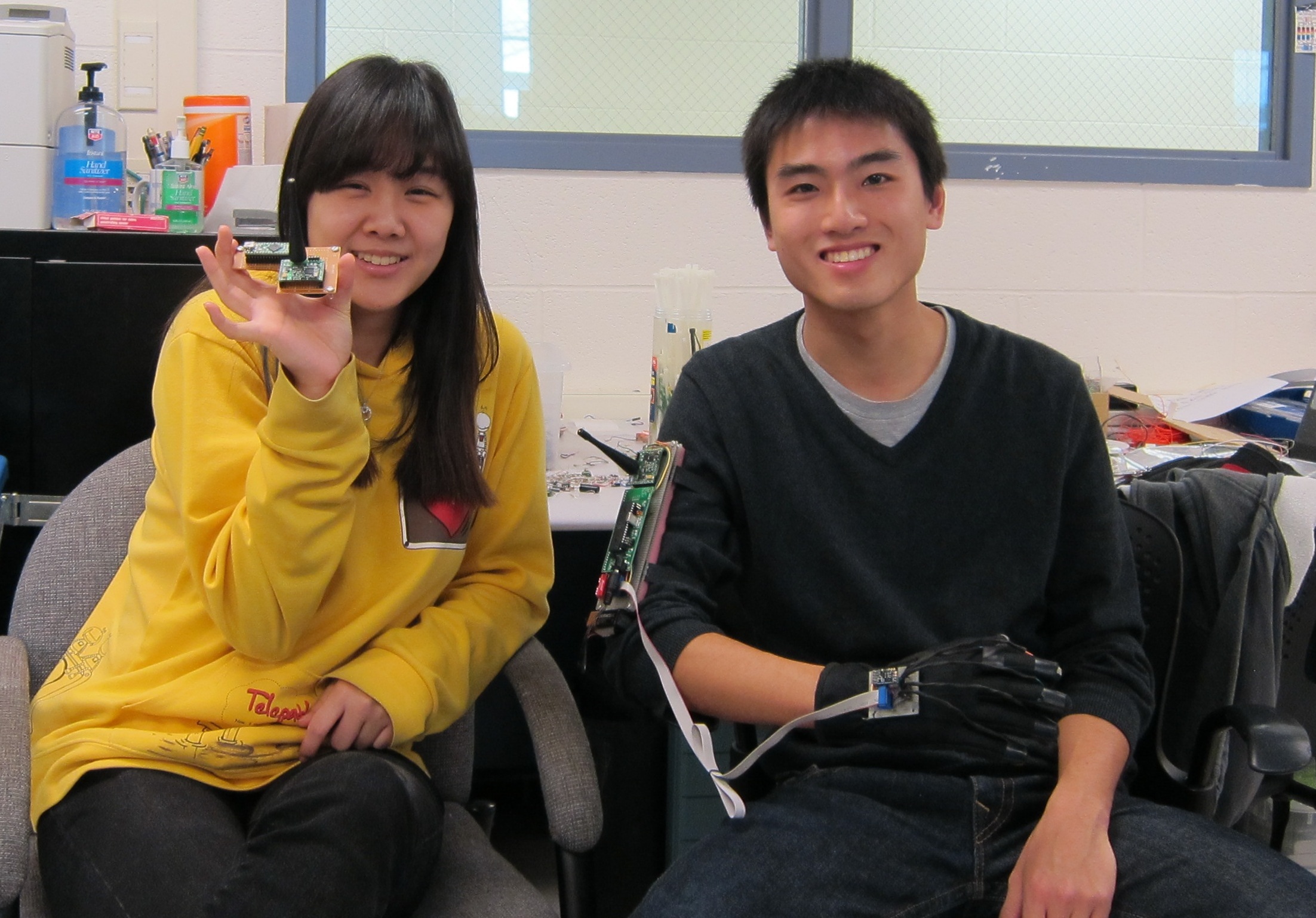
The engineers: Hyo and Adam.
Video demonstration.
High Level Design
Rationale and Inspiration
While brainstorming an idea for our final project, we decided to base our project idea around what we enjoy most about Electrical and Computer Engineering: computers. We felt that it would be interesting to somehow design a microcontroller based project which could somehow interface or communicate with our own personal computers. Additionally, we were originally inspired by a specific last project from the previous semester: a sign language translating sensor glove. This device was able to sense hand gestures and map them from a sign language alphabet to a standard English alphabet. With the thoughts of computer interfacing and hand motion in mind, we came up with this project idea.
The motivation for this project was to create an intuitive glove-based pointing device for multiple applications. The hope was to be able to create not just a working project but a fully-developed device in terms of intuitive functionality and practical, usable features. We note that past ECE 4760 project groups and outside hobbists have developed similar pointing devices, some glove-based and some not. While our end goals were similar to some previous projects, our intent was to only reference their projects as proof of the feasibility of our idea and ultimately to develop a more elegant, full solution to further the “glove mouse initiative”
Logical structure
At a high level, our design consists of two main parts: a glove and a base station. Operation of our device begins with the glove. A user wearing the glove can use hand tilt orientation and finger presses to operate the glove. The glove senses these user actions via two types of sensors: accelerometers and finger contact pads. After the glove's microcontroller processes the input data, it forwards a message a transceiver mounted on the glove unit. The transceiver then transmits this message wireless to a transceiver on the base station. The receiving transceiver forwards the the message base station microcontroller. Finally, the microcontroller converts the message into a computer HID user friendly format and moves the computer cursor appropriately.
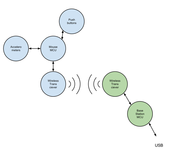
High-level block diagram of the system.
Hardware/Software tradeoffs
To interface our project with computers, we realized that we would be required to somehow implement a USB HID class device. During the planning stages of our design, we researched different ways implementing a USB HID and discovered that we could either proceed by doing this through software or hardware support. We came to the conclusion that our design would require an microcontroller in our base station in order to receive wireless messages and process the information. With this in mind, we decided it would be a more practical and simple to purchase a single hardware board that could perform both these functions. Almost too fittingly, we found a board that could perform the functions we needed and provided relevant example libraries, all within our budget. Additionally, we took into account the short time span we had for this project, and believed it'd be more effective to focus on developing our design than getting caught up in the details and semantics of the USB HID class.
Standards
Our design requires a computer to recognize our device as a human interface device, and thus our design must abide by USB HID specifications. This is implemented in the referenced USB mouse library used with our Teensy++ 2.0 microcontroller. Our design also features low powered radio transceivers using frequency-hopping spread spectrum. To follow FCC regulations, we use an FCC approved set of transceivers (this is detailed more below in Legal Considerations).
Hardware Design and Implementation
Hardware Overview
As mentioned above, the physical design of our project includes two main parts: a glove unit and a base station. The glove unit's main purpose is to process information from sensors and transmit the user input to the base station. The base station's purpose is to receive the glove's sent data and forward it to the user's computer in a HID class friendly format. Each unit has its own unique microcontroller and respective peripherals, which are detailed more below.
Glove Unit
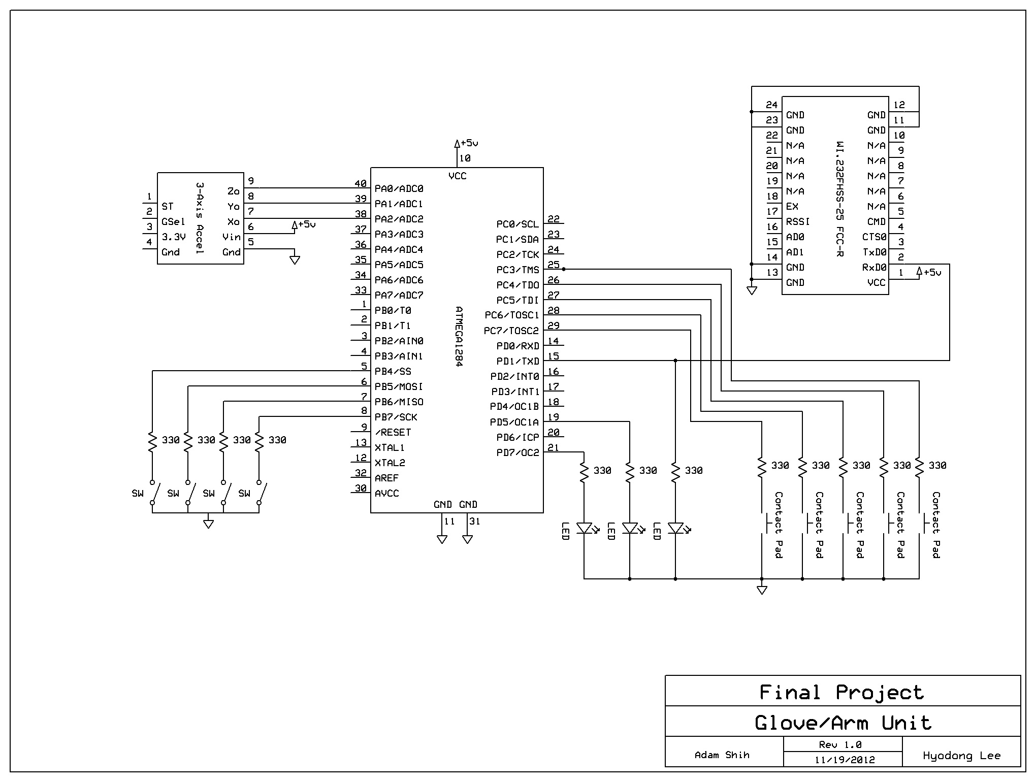
The Glove Unit is the set of hardware that the user physically wears during operation of the Glove Mouse. It carries a Atmega1284 microcontroller mounted onto a custom PCB designed by Bruce Land. Connected to the glove's microcontroller are 5 contact pads, a 3-axis accelerometer, a wireless transiever, 3 different colored LEDs, and a 4 pins of a 8-pin DIP switch.
The user of the Glove Mouse has two primary modes of input as well as one auxiliary mode. The primary modes of input are hand orientation for mouse movement control and buttons for mouse clicks and control over movement enabling. Hand orientation is sensed by the 3-axis accelerometer in terms of tilt, and outputs an analog voltage to pin A.0, A.1, and A.2 of the glove MCU. These pins are connected to the Atmega1284's internal analog-to-digital convertors, and are converted to a char value between -128 and 127. Button presses are sensed by contact pads placed on the sides and pads of the glove's fingers. The contact pads are connected to pins C.3 through C.7 on one side and MCU ground. Each pad simply shorts the microcontroller's input pin (originally pulled high via software) to ground. Contact pads are wired in series with a 330 Ohm resistor to protect respective microcontroller ports. Similarly, 4 DIP switches are wired from ground in series with a 330 Ohm resistor to MCU pins B.4 through B.7 to control mouse user preference features such as sensitivity, axis inversion, and rapid fire clicking.
In terms of outputs, the Glove Unit's MCU is connected to the input of the of a wireless transceiver. Specifically, it connected to port D.1, the first of two USART channels supported by the Atmega1284. This port is appropriately chosen to interface with the Radiotronix transceiver used, which communicates via USART. Additionally, the Glove Unit features 3 status LEDs, connected to port D.7, D.5, and D.1. Respectively, these LEDs provide information regarding power on, button clicks, and communication between MCU and transceiver.
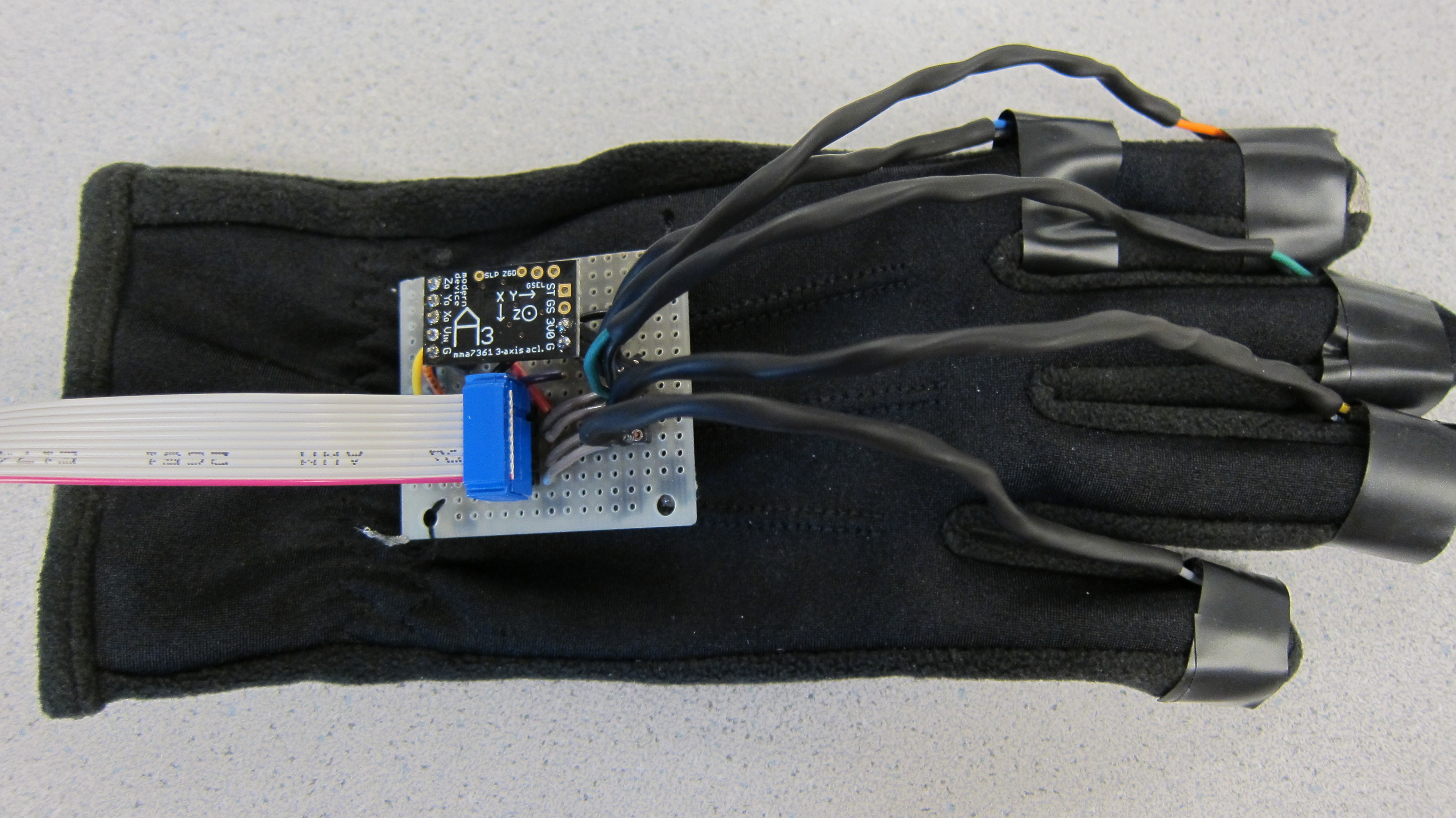
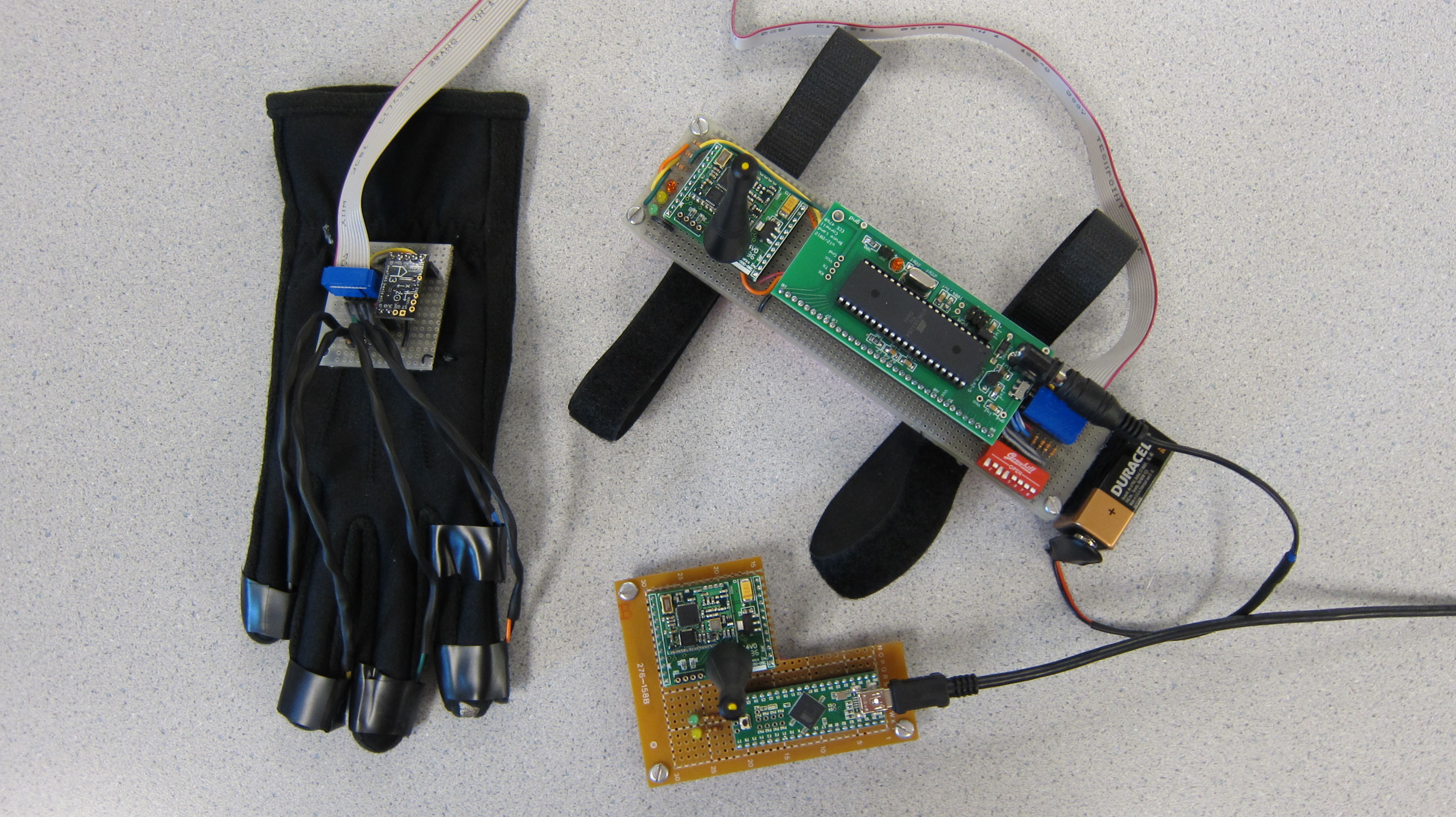
The glove. [Full-size]
The armband. [Full-size]
Close-up of glove solder board. This provides the detachable interface between the armband and glove's sensor hardware
Physically, the Glove Unit was assembled as two separate pieces: a custom glove and a custom arm band. Together, these form the circuitry for the one functional module described above. We chose to separate this design into two pieces due to the size of our components and the limited space avalible on the glove. As a result, the glove actually only carries a small solder board that is connected to all the acclerometer and contact pads. The solder board is sowed onto the back-hand area of the glove. A 5x2 header to connected to this board in order to interface with the arm band, which carries the rest of the components/circuitry plus a 9V battery for power. A simple female-to-male flat-wire is used to connect the two pieces. This physical design and choice of mounting location on the user is chosen for wearbility, comfort, and hardware safety.
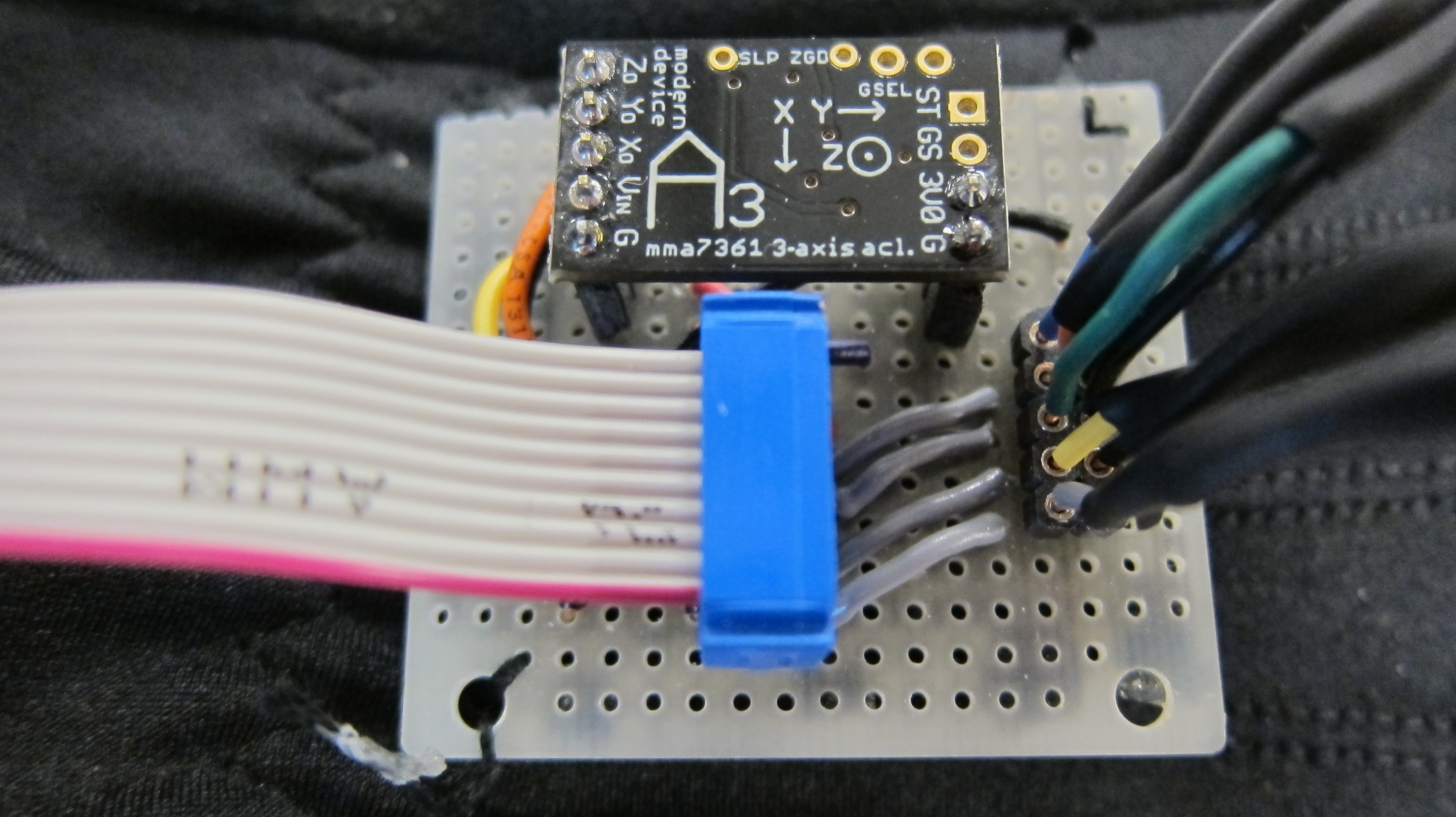
Accelerometer
In order to detect and map user hand motions to mouse cursor movement, we chose to use accelerometers to measure hand tilt and orientation. Specifically, we chose to use a Modern Device 3-Axis Accelerometer Module. This chip carries a Freescale MMA7361 three-axis analog accelerometer. The 3-Axis Accelerometer Module additionally features a low-dropout voltage regulator (Microchip MCP1700) to provide 3.3V power to the MMA7361 and 10nF capacitors on the outputs of the accelerometer to minimize clock noise. Because of this, we were able to use the accelerometer module straight out-of-the-box (connecting its power input to Vcc).
Contact Pads
We chose to use contact pads in order to detect pointing device button commands. Originally, we had decided to purchase small push buttons and install them on each of the glove's finger pads. However, due to pricing, minimum order quantity, and size constraints, we could not find a feasible solution. As such, we determined that we could build soft contact pads from available lab materials. The contact pads we built have the same exact functionality and user interface as typical push buttons: each contact pad features two output wires that are shorted together when contact pad is pressed. Contact pads are connected to glove's design via one lead to ground and the other to a 330Ohm resistor in series with the MCU's input ports.
Contact Pad Construction
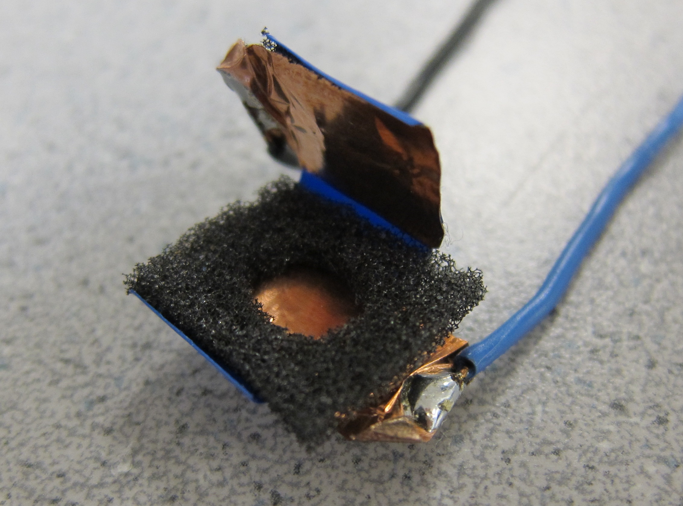
Contact pad assembly: two layers of copper tape separated by hole-punched foam.
To build a contact pad, we used copper tape, copper wire, foam, and electrical tape. First, we cut off thin 1” by 0.5” slices of foam, approximately .25” thick. We cut 2 rectangular strips of copper tape that were slightly smaller than the foam in terms of length and width. It is important that the rectangular copper strips can be completely covered by the foam to prevent any unwanted short circuits. Next, we soldered a wire onto the conductive side of each piece of copper tape. We then hole-punched out a space in the foam and sandwiched the foam in between the two pieces of copper tape. Finally, we wrapped foam and copper tape with electrical tape.
The contact pad design is based on the idea that the foam keeps the two pieces of copper tape separate and from touching during non-use. During operation, when pressure is applied to the pad, the foam is depressed and when enough pressure is applied the two copper strips will touch via the through-hole created, thus shorting the two ends together. We to test the proper construction of our contact pads, we simply connected an Ohmmeter to the two leads and and checked for proper short circuit during operation and open circuit during non-use.
We ended up creating several “prototype” iterations of our design throughout this project. The dimensions of materials we used were optimized for our application, and can easily be changed for other applications requiring larger or thicker pads.
Prototype Board
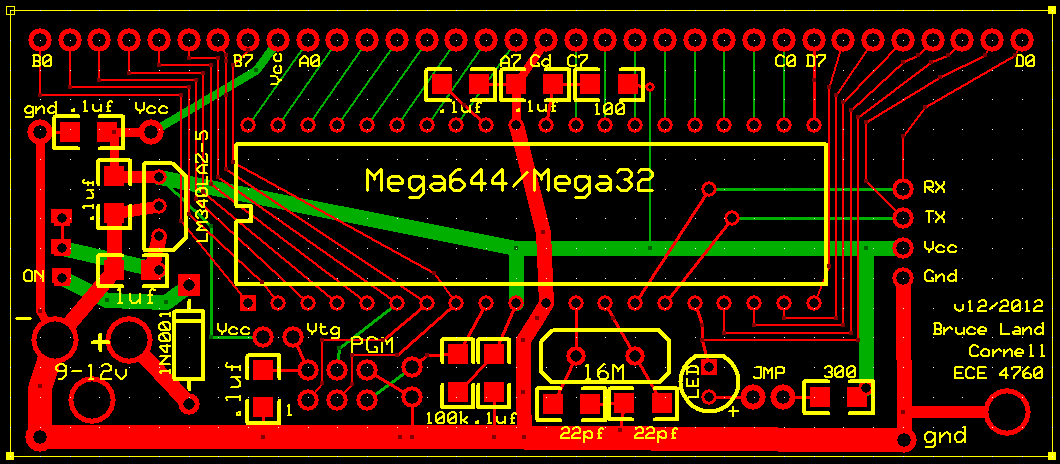
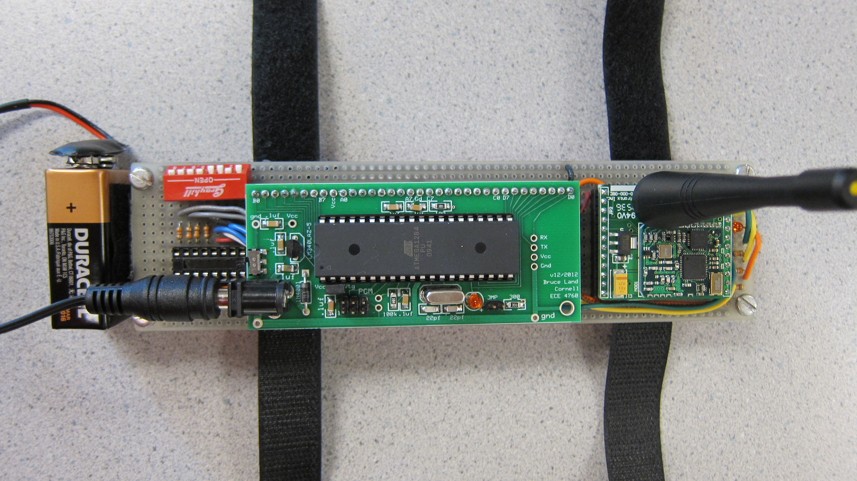
Our Glove Unit includes a custom prototype board designed by Bruce Land to connect to a Atmega 1284 microcontroller. The prototype board makes it easier for to connect a target microcontroller with external inputs and outputs. For example, we built our board with a CTX077 16Mhz external crystal, LM340LAZ-5.0 voltage regulator, surface mount power switch, 2.1 mm power plug, a debugging LED, and a 6-pin male header for connecting to a AVRISP mkII programmer. These features made testing much simpler and allowed us to quickly switch out the microcontroller if needed (in case of MCU damage or failure).
Wireless Transceivers
The wireless transceivers used in our project are both Radiotronix WI.232FHSS-25-FCC-R. These transceivers were graciously donated to Professor Land, who in turn donated a set to us. The glove unit and the base station each sport a single transceiver. The glove unit's transceiver strictly receives input from the glove microcontroller and transmits data to the base station's transceiver, which then forwards the data to the base station microcontroller. Each transceiver is powered by the Vcc output of its respective microcontroller, and has all six of its ground contacts connection to microcontroller ground. The transceivers operate at 902 to 928 Mhz.
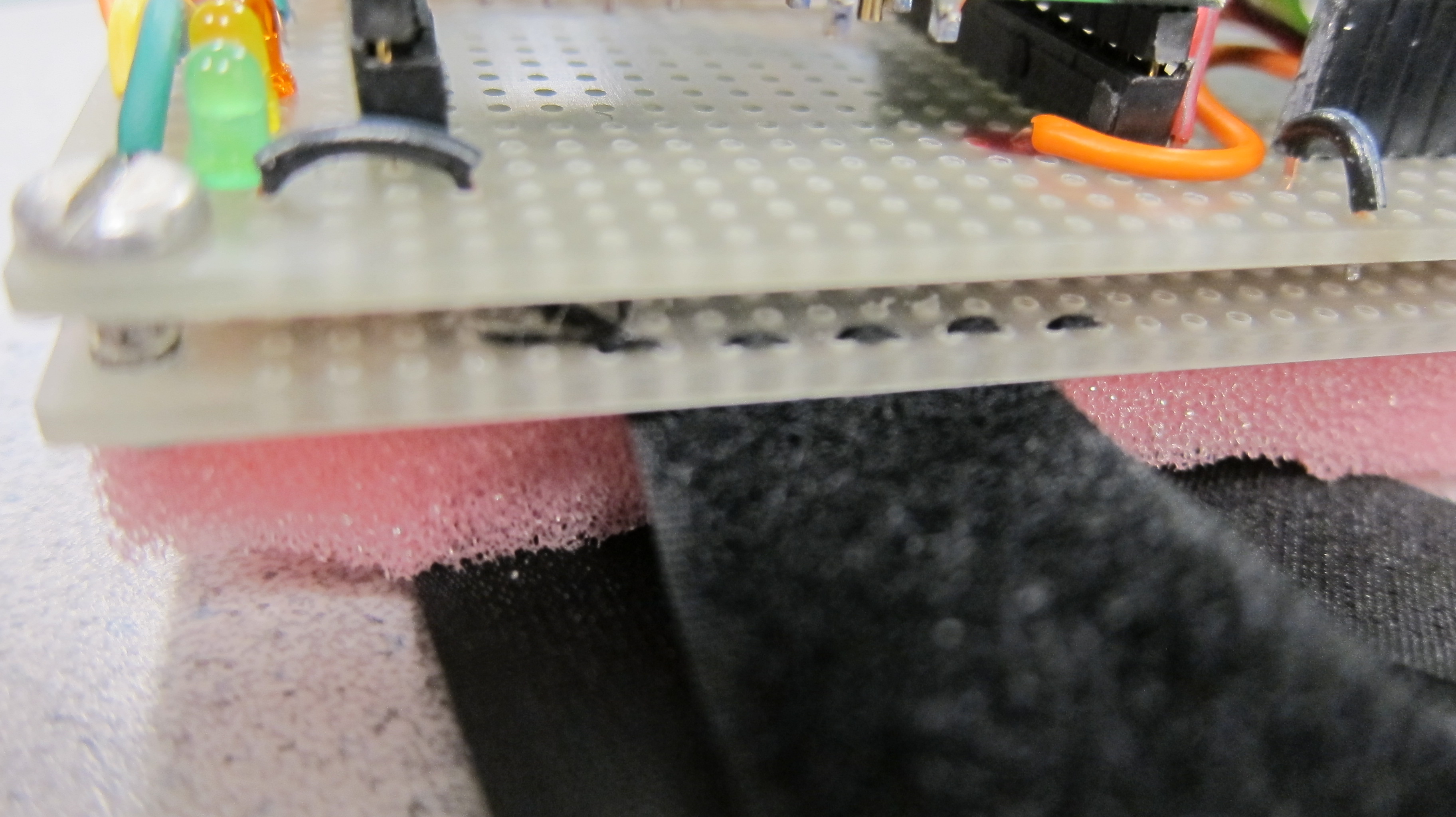
Arm Band Mounting Harness
Close-up: Glove Unit's primary solder board with test harness attached. Sewing work for attaching velcro to harness visible.
In addition to the electrical design of our glove unit, we also designed a simple yet functional mounting harness for the glove unit's main solder board. The mounting harness is made up of an additional solder board with 2 velcro straps and ESD foam. The idea behind of a separate mounting harness was to provide modularity and easy adjustablilty to the arm band while also providing some isolation between electrical and skin-touching parts. The gap between the two solder boards helps prevent electrostatic discharge (ESD) from the velcro and user's clothes plus body. Additionally, we added a foam of ESD foam to the mounting harness for more ESD prevention. To securly affix the velcro to the harness, we have sown and glued the welcro to the second solder board. Four screws are used to hold the two boards together and at a uniform distance apart.
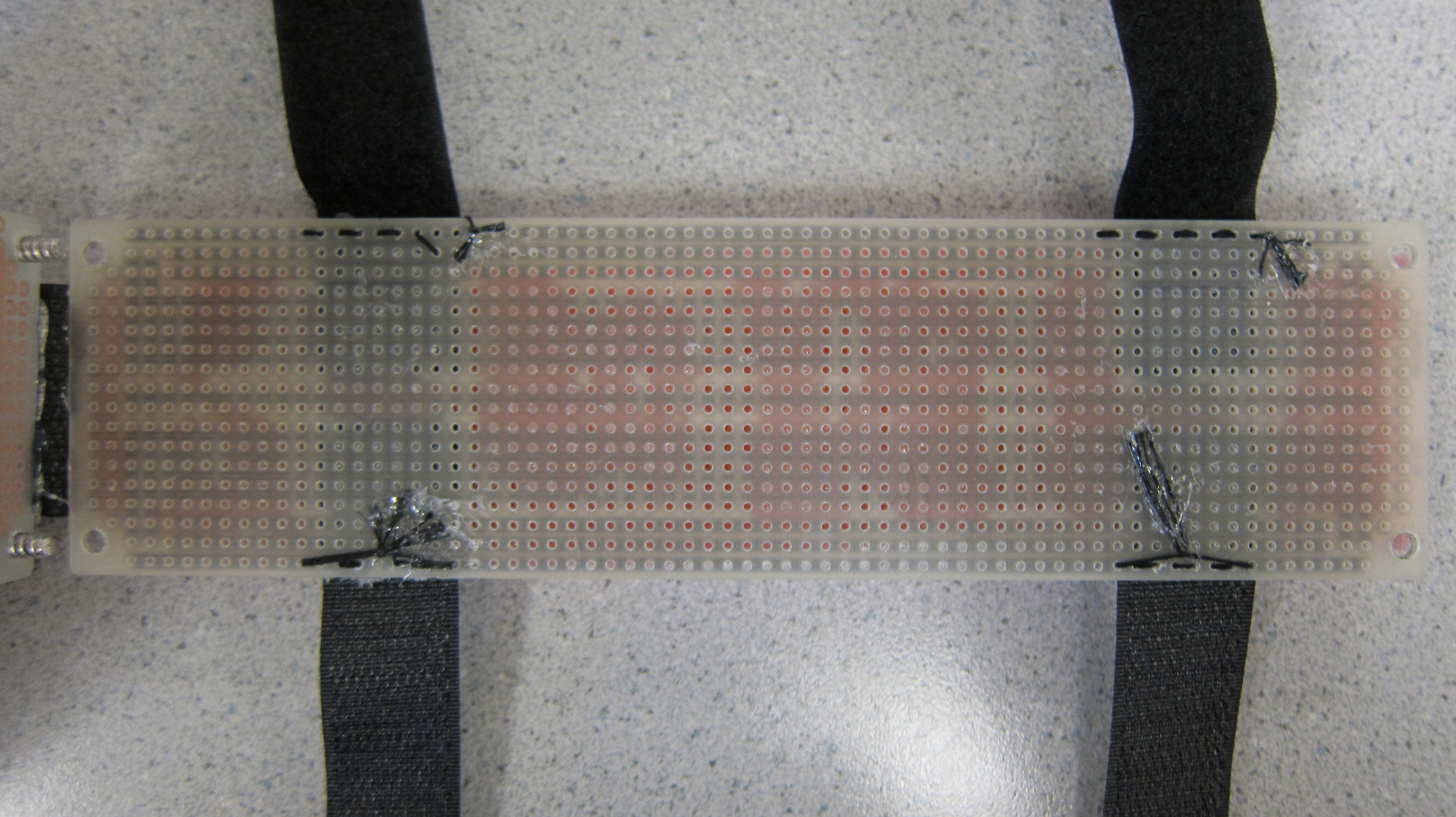
Mounting Harness
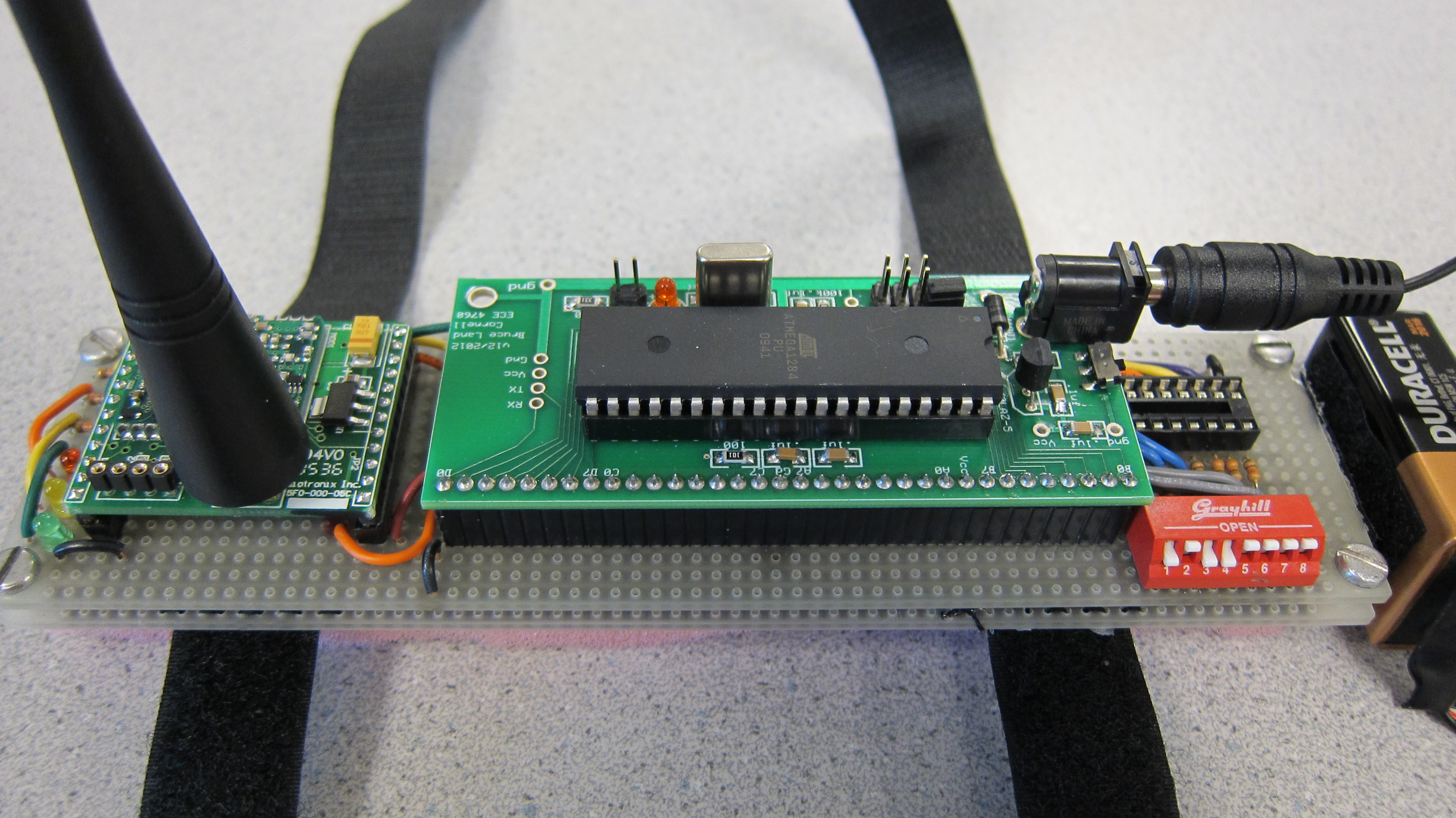
Base Station
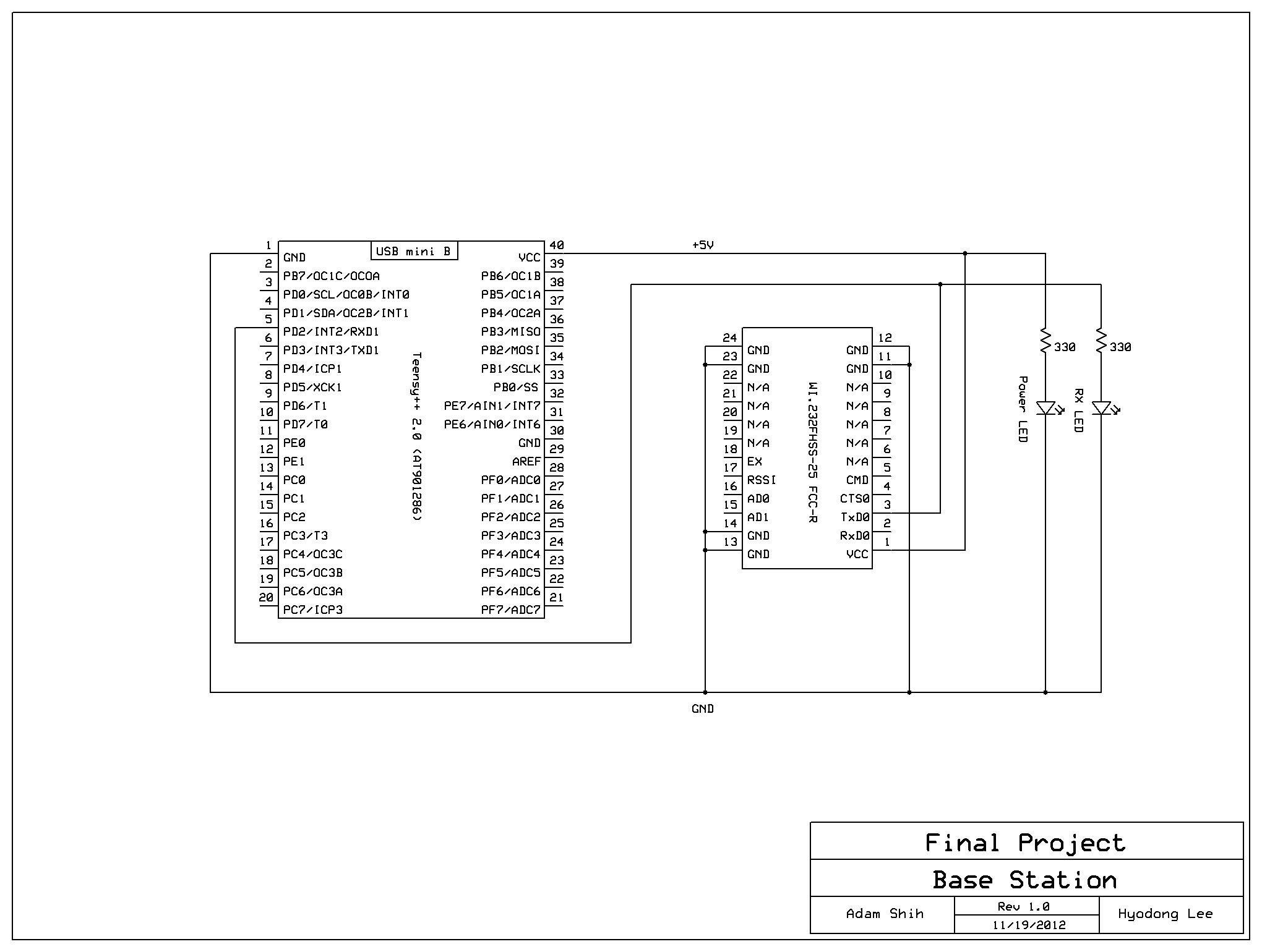
The base station serves one important purpose: to receive packets sent from the Glove Unit, wrap them in a proper HID format, and forward mouse commands to the user's computer. It carries a AT90USB1286 microcontroller mounted on a Teensy++ 2.0 board. Connected to that microcontroller are 2 different colored LEDs and a wireless transceiver.
Wired connections on the base station solder board are fairly elementary. The base station microcontroller receives input to RXD1 (pin D.2) from the wireless transceiver's TXD0 output. Communication is processed via USART in the same fashion as in the glove unit. The wireless transceiver Vcc and ground are connected to MCU Vcc and ground. The MCU is powered via the Teensy's USB mini B plug. For debugging and status updates, one LED is connected to MCU Vcc (so it turns on when the base station is powered) and another is connected to the transceiver-to-MCU wire, so it flickers during message receives. Two 330 Ohm resistors are wired in series with the LEDs to prevent MCU port blow-out.
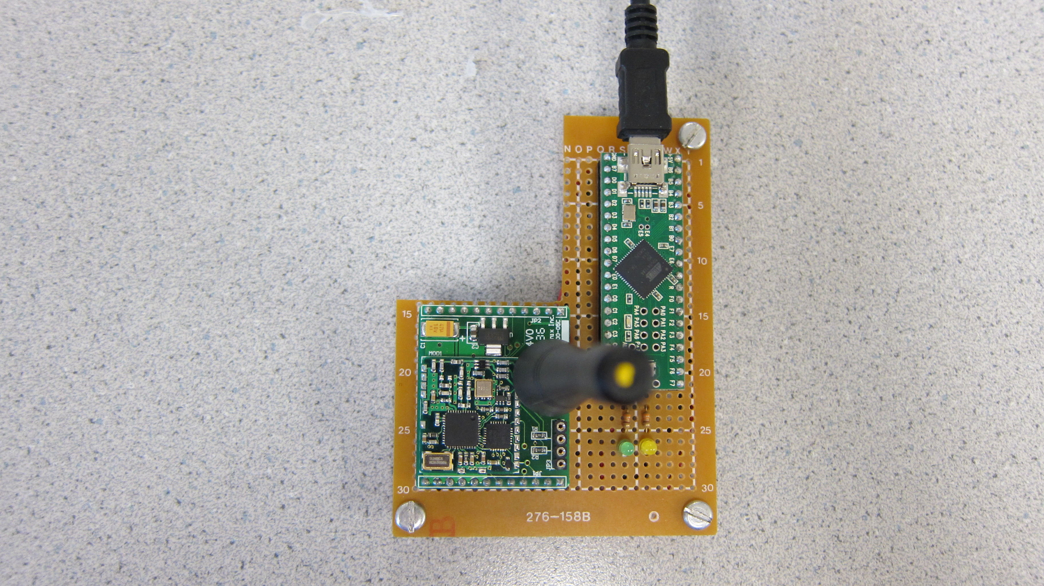
The base station. [Full-size]
Teensy++ 2.0
The Teensy++ 2.0 is microcontroller development board supporting USB-based projects. It features a AT90USB1286 microcontroller. We chose to use a Teensy over the duplicate of the glove MCU for several reasons. The main criteria for selecting this particular device was its support for USB communication. This way, we wouldn't have to develop/use additional software for the required USB HID class. Additionally, the Teensy carried a Atmel microcontroller that used very similar specifications to what we were already used to from the Atmega1284. Lastly, the Teensy was avaliable as a very small, user friendly package with several supporting example code libraries.
Software Design and Implementation
Mouse Movement
In this project, a 3-axis accelerometer is used to control cursor movement. The accelerometer reads the tilt of each axis and outputs each as an analog voltage. The three ports of MCU are connected to the tilt outputs of the accelerometer respectively. Then, each of the voltage value of tilt is converted to digital numbers. These numbers are converted to final mouse movement values by noise detection and scaling. In order to provide accurate mouse-motion and a user-friendly interface, several different types of post-processing are applied to the converted ADC values.
Analog-to-Digital Conversion
The Atmega 1284 microcontroller contains several single-channel internal analog-to-digital converters (ADC), which each convert an analog input voltage signal to a digital value. The x, y, and z-axis tilt outputs of the accelerometer are connected to the ADC channel 2, 1, and 0. Once the ADC converts the tilt voltage value into digital bits, the digital numbers are stored in ADC data registers. The ADC channel modes are set up such that only the high byte of ADC data register is read. We set the voltage reference to Vcc, and ADC prescalar to 128.
The ADC values are sampled by calling the readAccel() function every 8 milliseconds. The timer 0 compare match ISR (interrupt service routine) is used for regular ADC sampling. The timer 0 prescalar is set to 256 and the compare register is set to 250 time ticks. This allows the program to execute the ISR every 4 milliseconds. In the ISR, acceltime (the time counter for ADC sampling) in decreased. When acceltime becomes zero, its value is reset to 2 and readAccel() is called.
Initial Axes Calibration
When the move or scroll is enabled, the calibrate() function is called to read the current tilt values. This function averages 1024 samples to get reliable offset values, which are used as the starting reference point. By subtracting those offsets from every ADC sample, the user can start at any position and use that hand orientation as the current reference axes. Once calibration is finished, the ADC samples are read in the ISR. The corresponding offset value is subtracted from each sample. Then, each sample is zeroed if its absolute value is smaller than the threshold. We chose the threshold experimentally such that natural user hand quivering is treated as a noise instead of valid mouse movement. Because of the fact calibration should be executed before the program starts to read the ADC samples, the cli() and sei() (disable and enable the interrupt) functions were used to make this function atomic.
Flat vs Handshake Mode
Although any starting tilt position is allowed (theoretically), we wanted to consider a special case: handshake position as shown in the picture below. The hand position is more ergonomic and allows the user easier hand rotation in both directions. In this case, instead of x and y axes, the y and z axes are read out of the accelerometer. This allows the user an up-down motion to change the y cursor position, which is consistent with that of flat position.
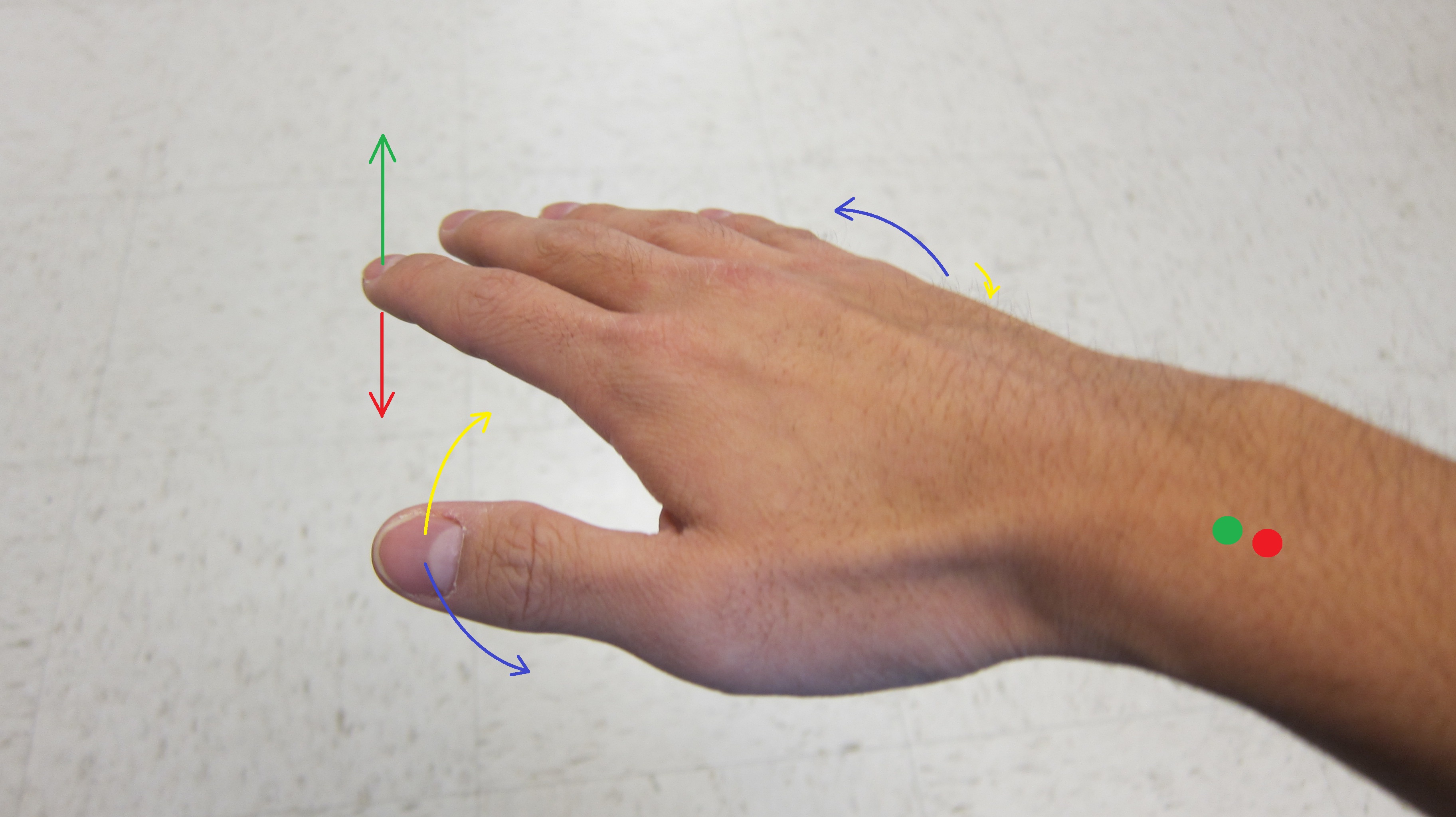
Hand positioning for flat mode. Blue rotation represents left movement, yellow is right, green is up, and red is down (the dot represents pivoting above that point). [Full-size]
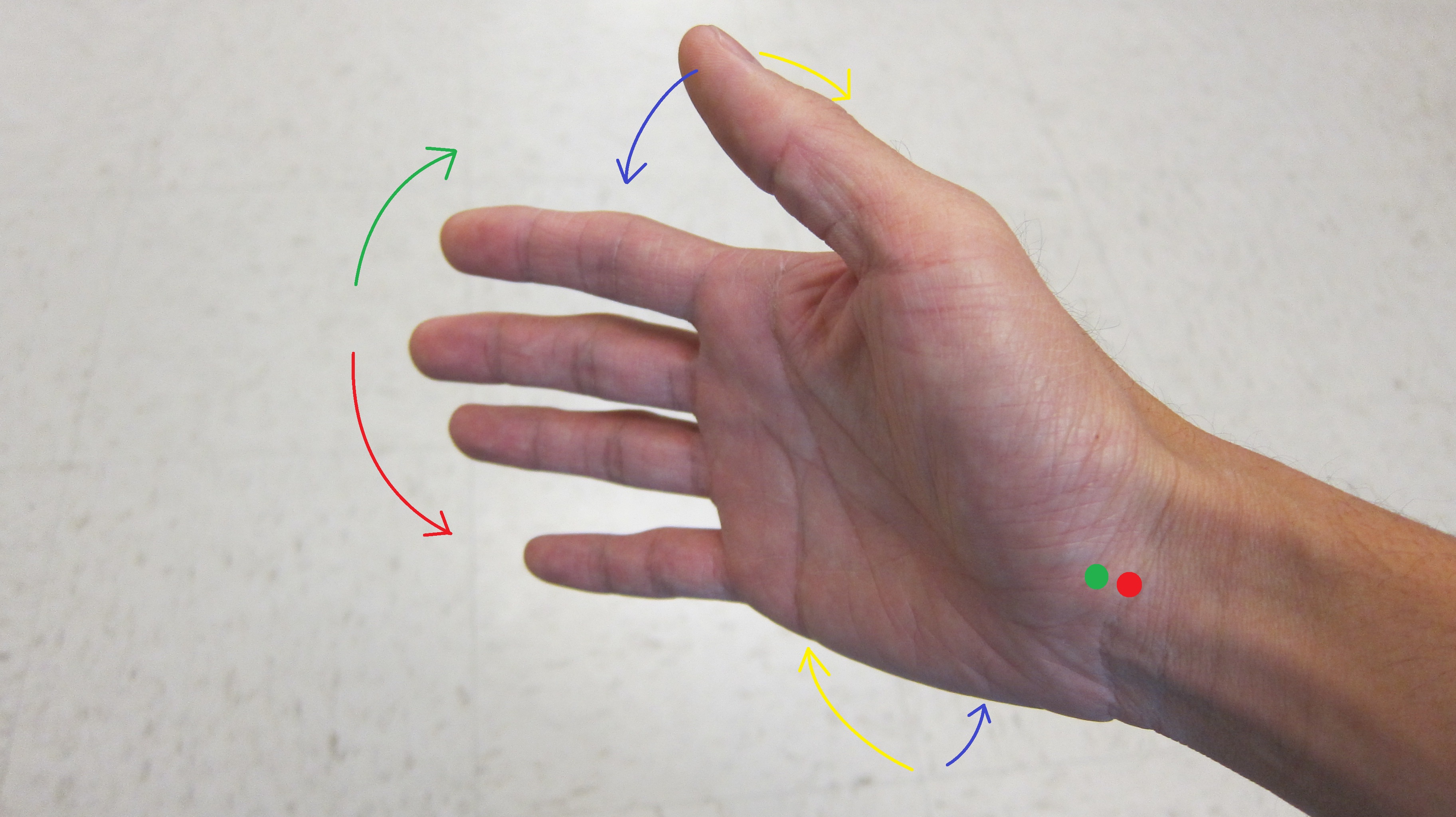
Hand positioning for handshake mode. Blue rotation represents left movement, yellow is right, green is up, and red is down (the dot represents pivoting above that point). [Full-size]
Axis Inversion
As one of the user operation options, our glove mouse allows the users to invert the axes of mouse movement. When inverting DIP switches for both x and y axes are off, the cursor moves in normal direction. For example, left tilt will move the cursor to the left, and so on. If x-axis inverting is switched on, left tilting cursor movement towards the right. This function was implemented by setting a flag based on the switch status. If switch is off, the flag is set to be 1; if switch is on, the flag is set to be -1. The flag is then multiplied to the ADC sample. This option was added to give more freedom to users who have different directional preferences.
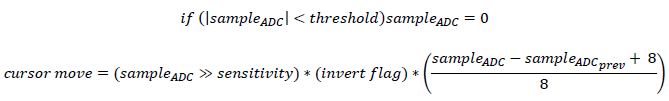
Cursor Accerleration
Our glove mouse also has the ability to mimic the cursor acceleration: the faster the user changes the tilt, the faster the cursor moves. The tilt change rate can be obtained by subtracting the previous tilt value from the current. To prevent sudden bursts of movement, we implement nonlinear scaling for calculating the cursor acceleration as shown in equation below.
Sensitivity
A user of the Glove Mouse can select low or high sensitivity for mouse movement by DIP switch. At high (or normal) sensitivity mode, the cursor moves with reasonably slow speed such that the user can operate normal tasks on the computer. At low sensitivity mode, the cursor moves further with relatively small tilt. This was designed for presentations, where the cursor moves faster along the big screen with smaller user motion. The sensitivity is controlled by right shifting the ADC sample value by different numbers. More right shifting results in slower movement. The value for shifting for each mode was chosen experimentally.
The equation for calculating the final value of the cursor speed is shown below:
Packet Format between Transmitter and Receiver
Button Clicking and Switching
Contact pad buttons are connected to the port C.5, C.6, and C.7 buttons for left click, middle click, and right click. When each button is pressed or released, a packet with the corresponding click information is transmitted to the base station to perform mouse click or unclick. In addition, move enable and scroll enable buttons are connected to port C.4 and C.3. When these buttons are pressed and then released, the corresponding flag is toggled. If move enable flag is on, the ADC is sampled and the cursor speed is transmitted to the base station. Similarly, the scroll command is transmitted to the base station only if the scroll enable flag is set. We designed scroll enable to have priority over move enable.
Along with the normal button clicks, a rapid fire mode was added as a user option. When the switch for rapid fire mode is on, the mouse is clicked repeated approximately every 60ms while left click is depressed. When left click is pressed and the rapid fire mode switch is on, the flag for sending rapid fire is set. In the ISR, if the rapid fire flag is on, the rapid fire message is transmitted every 30ms.
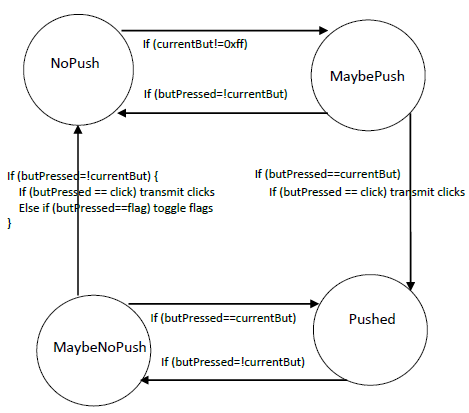
Every button press and release is debounced using a state machine with four states. The state is first initialized as NoPush, where it waits for a button press. The port C pins were set as inputs with respective pull-up resistors turned on. If any button is pressed, the corresponding bit in PINC will be set to low. If a press is detected, the state changes to MaybePush, where any change of PINC value is checked. If current PINC value has changed, then it may not be a valid press and so the state returns to NoPush. If PINC value remained the same, it is a valid press and so the state proceeds to Push. On this transition to the Push state, button press messages are transmitted. The release is debounced similarly, and the button release messages are transmitted or the move/scroll enable flags are toggled on the transition from Push to NoPush. The detailed state diagram is shown below:
Packet Format between Transmitter and Receiver
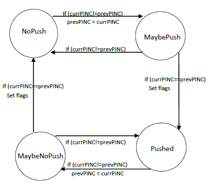
The four switches are connected to port C pins and used to select the user options as illustrated in the previous sections: sensitivity, rapid fire, invert_x_axis, and invert_y_axis. DIP switch on and off switching is also debounced using the similar state machine to the button state machine. State is again initialized as NoPush and changes to MaybePush if PINC value is changed. In the MaybePush state, if the switch is change is determined to be valid, the state proceeds to Pushed. On this transition, the flags are set to corresponding values based on the switch status. The difference of this state machine from the previous one is that the Pushed state has identical functionality as the NoPush state. This is necessary because the switch does not require a set of press and release. The state machine should debounce either on or off, once. The detailed state machine diagram is shown below:
Packet Format between Transmitter and Receiver
Wireless Communication
For wireless communication between the glove (Atmega 1284 microcontroller) and the base station (Teensy 2.0++), two radio transceivers (WI.232FHSS-25-R) were used. Each radio transceiver and microcontroller communicates through wired connection between USART ports. The glove side MCU converts the user’s glove control into a packet. The packet is then loaded onto the transceiver and is transmitted to the base station. The transceiver on the base station receives this packet and passes it to the base station MCU (Teensy 2.0++). The base station MCU finally decodes the packet information and converts it into a real mouse cursor movement or click.
All four units in our project are programmed with a baud rate of 57600 bits/second. The glove MCU and transmitting transceiver pass data to the base station transceiver and MCU respectively. Thus, glove MCU is initialized as transmitter enabled while the base station MCU is initialized as receiver enabled for USART setting. The USART is operated in SPI mode with odd parity check enabled, 2-bit stop bits, and 9-bit data size in a frame.
The packet transmitted from the glove side to the base station contains 6 different bytes.
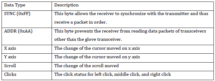
Packet Format between Transmitter and Receiver
The glove transmitter sends packets that correspond to the action performed by the user on the glove. The different actions are encoded by the glove MCU as below:
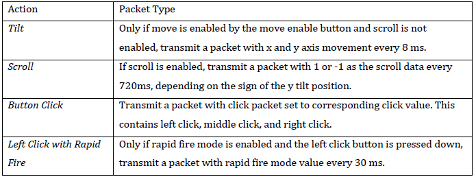
Action and Packet Type Encoded by the Transmitter
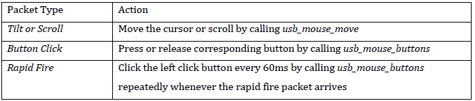
Action and Packet Type Decoded by the Base Station
Teensy USB Mouse Library
The mouse interface source code could be downloaded from the Teensy website. Inside the code, there are two main functions that we used: usb_mouse_buttons and usb_mouse_move. The usb_mouse_buttons function takes the left click, middle click, and right click bits as inputs. If the bit is set to one, the mouse presses; if the bit is set to zero, the mouse releases. The usb_mouse_move function takes the change in x axis, y axis and scroll as inputs and moves the cursor or scroll with the given amount.
Results
Finished prototype Glove Mouse [Full-size]
Speed of Execution
The Glove Mouse responds to user input fairly quickly. There is a slight delay on the order a several milliseconds when clicking and changing cursor direction. This very small and barely noticeable delay is due to how tightly we bound the several computations that take place in our interrupt service routine. During the development phase of this project, we sucessfully tested the glove's primary functions of cursor motion and clicks with viritually no noticeable delay. The addition of several extra user preference features added several calculations on our system, and caused us to slightly slow down the cursor update rate.
Accuracy
The accuracy of our entire device as a whole is fairly good. In terms of basic functionality 2-D cursor movement and mouse clicking is successfully achieved. Accelerometers placed on the glove measure tilt very well, and thus allow the Glove Mouse to adjust the cursor speed based on the magnitude of tilt. The Glove Mouse can also detect the starting orientation and calibrate the initial axes well. The contact pads and button debouncing state machine are also reponsive and function properly. However, we've noticed the springiness of the contact pads degrades over time. We attribute this to depressing of the foam after hours of testing and hundreds of button presses we put them through.
We believe that some accuracy is lost via dropped packets between our the tranmission of data from the glove unit to the reception at the base station. We first noticed while testing the rapid fire clicking feature we added towards the end of the design phase. Occasionally, the mouse does not unclick after constant rapid fire clicking. Although we explicitly send a release left click message to the base station, the base station does not always finish rapid-fire by unclicking the cursor and leaves it "held down." We only notice this very occasionally while testing rapid fire clicking, and believe this is because mode of operation subjects the system to many more clicks, thus increasing the chance we'll see a dropped packet in a noticeable situation. Other than that, the glove performs correctly with expected accuracy.
Usability
The device is usable to anyone who is able to use a standard computer mouse is able to pick up the glove and learn to use it. There is a small learning curve to controlling a computer mouse with hand tilt rather than existing paradigm everyone knows (2-D device positioning). More notably, users with differently sized hands/fingers, unable to fully control their fingers may, or unable to comfortablly turn their wrists in all directions may have some difficulting operating the glove. Depending on the specific situation, difficulty in using the glove may be alleviated through adjusting the sensitivity of the cursor movement and location of the contact pads.
For prototyping purposes, we have only built a right-handed glove, but note a left-handed glove can be built using the same exact design with the exception of using a complementary glove.
Safety
We designed many parts of our physical Glove Mouse construction around safety. As mentioned in the Hardware Design and Implementation section, we took several steps towards isolating the electrical circuits of the arm band away from the user. All wires are insulated or hidden from easy user access. Like the arm band, the glove's construction avoids putting electrical parts in direct contact with the user. We add wire slack between the glove and the armband to give the user room to freely move, but tie extra cable together to prevent tangling during arm movement.
Conclusions
Summary
Overall, the results of our project met our expectations outlined in our project proposal. Our final prototype is able to effectively control mouse movement and clicking with user hand gestures. We are pleased with the organization of both our final hardware and software.
Despite our satisfaction, we were not able to achieve one goal we had set at the beginning of this project. Initially, we had envisioned our glove to be able to control mouse movement by position of the glove in a 2-D plane. This design would have been more intuitive and similar to the exisiting paradigm of standard computer mice, lowering the learning curve associated with using the Glove Mouse. After spending several hours on this endeavor, we realized that we would probably not be able to integrate our accelerometer output to extract the data we needed in a useful fashion. With the grade of parts that we could afford with our budget, plus the short amount of time we had, we decided half-way through the project to shift our efforts towards controlling the mouse cursor with accelerometer tilt readings instead. Since we suspected this difficulty at the start of our project, our realistic expectation was to try 2-D positioning, but plan for tilt-based movement control as an alternative. Thus, we feel as if the expectations of this project have still be met.
The final prototype created from our 4 week project serves as a additional proof-of-concept to similar existing projects. Because of this, we believe that this design has much room to grow. Primarily, we believe that a smaller wearable unit (for example, a single glove without an armband) would be more practical for everyday use. Our project is built with a small budget in mind and with easily usable, but not necessarily the smallest, parts. With more time, a custom PCB could be used to simplify the physical construction. Additionally, higher resolution cursor movement could be attractive for commercialization.
No designs were reverse engineered in the creation of our project. As mentioned already, we utilized the Teensy C libraries for proper USB HID communication. We also built-off the idea of arm-mounted circuit used in previous glove-based projects. This project would not have been as successful without the confidence provided by previous student projects. As a result, we want to forgo any patent opportunities related to this project, and leave our work as a open-source basis for any related future student or hobbiest projects.
No non-disclosure forms were signed during the duration of this project.
Ethical Considerations
Through the 4 week duration of this project, we complied with the IEEE Code of Ethics. During the design and assembly of our project, we consistently considered the safety and welfare of ourselves, the supposed user of this device, and the general public. As mentioned in previous sections, we covered all exposed wires and also organized any unnessarily long and potentially dangerous parts. We also took into consideration the other groups using the same lab space, and did our best to keep the area from getting cluttered by clearing our work station and sharing public tools with others. When approached for an opinion, we gave honest criticism of our peers' technical work and assisted them when appropriate. All referenced work is appropriately acknoledged and credited. Lastly, we do our best to be practical and realistic in stating the successes and failures of our project in our design and results sections.
Legal Considerations
The model of transceiver we used in our project is specifically a FCC approved wireless module. It is designed to operate between 902 and 928 MHz, and has a power rating of approximately 11dBm with a max of 13dBm (slightly less than 20mW).
According to the Bulletin 63 by the FCC OET, low power transmitters should compile with Part 15 and have a non-user-detachable antanne or unique antanne connector to prevent different antannae from being connected and potentially increasing power output to a harmful level. Our project does not follow this antanna requirement, as the transceivers are in adjustable reach of the user.
Intellectual Property
All software designed was written by us, with the expection of the USB mouse library provided by PRJC.com to all Teensy developers. All components used to build our project were avalible via ECE 4760 lab stock or local craft store.
Appendices
A. Code Listing
B. Schematics
Glove unit:
Base station:
Prototype Board PCB:
C. Parts List and Costs
| Part | Unit Cost | Vendor | Quantity | Total Cost |
| Custom PCB (designed by Bruce Land) | $4 | Lab Stock | 1 | $4 |
| Atmega 1284 | $5 | Lab Stock | 1 | $5 |
| Teensy++ 2.0 (w/ headers) | $27 | PRJC | 1 | $27 |
| Radiotronix WI.232FHSS-25-FCC-R Transceivers | $0 | Donated by Bruce Land | 2 | $0 |
| Modern Device 3-Axis Accelerometer Module | $10.95 | Modern Device | 1 | $10.95 |
| Contact pads | $0 | Built from lab materials | 5 | $0 |
| Isotoner Smart Touch glove | $4 | Walmart | 1 | $4 |
| Solder board | $2.50 | Lab stock | 4 | $10.00 |
| 40-pin DIP socket | $0.50 | Lab stock | 2 | $1 |
| Header pins/plugs | $0.05 | Lab stock | 147 | $7.35 |
| SIP Sockets | $0.05 | Lab stock | 10 | $0.50 |
| DIP switch | $0 | Lab stock | 1 | $0 |
| Flat cable | $2 | Lab stock | 1 | $2 |
| LEDs | $0 | Lab stock | 5 | $0 |
| Screws | $0 | Lab stock | 3 | $0 |
| 9V battery | $2 | Walmart | 1 | $2 |
| Laser diode | $0 | Lab stock | 1 | $0 |
| Velcro (30") | $3.79 | Michaels | 1 | $3.79 |
| ESD Foam | $0 | Lab stock | 1 | $0 |
| Wire | $0 | Lab Stock | 10' | $0 |
| Resistors | $0 | Lab Stock | 14 | $0 |
| Total Cost | $77.59 |
D. Distribution of Work
Adam
- Overall Hardware Design
- Contact pad assembly and test
- Final product assembly
- Hardware Schematics
- General software debugging
- Project website
Hyodong
- Overall Software Design
- Wireless transceiver firmware
- State machine programming
- ADC integration and debugging
- Custom PCB soldering
E. Additional Images
References
Below are links to external documents, code, and websites referenced and used throughout the duration of this project.
Datasheets
Vendors
References
Acknowledgements
We'd like to thank Professor Bruce Land for donating lab parts to us, helping us work through problems, and being a fantastic lecturer. We'd also like to thank all the TAs for their help, with a special thanks to our TA Terry. Lastly, we'd like to give credit to the following previous projects for inspiring us with their glove-based projects: Sign Language Translator, Mister Gloves, and Rock-Paper-Scissor Sensor Gloves.