"A Reversi board, play by touching the screen and lighting up the LED pieces."
Project Soundbyte
Introduction top
For our final project in ECE 4760, we designed and implemented a Reversi board consisting of hardware, a microcontroller, and a touch screen. Sixty-four bicolor (red and green) LEDs were implemented as the black and white pieces of the game. Players could simply light up a LED (place a piece) by touching the touch screen in the position right above the corresponding LED. Other LEDs would be flipped automatically according to the rules of Reversi, which is programmed into the microcontroller.
We designed this board for several reasons. We made this board an integration of board and pieces for the convenience to carry. And people will not be worrying of losing pieces when carrying the board around. Players do not necessarily have to find a flat platform to place the board because the pieces are free of tilting or sliding; players can easily move the board to anywhere else when needed, and resume the game right away. Additionally, players do not have to flip the pieces by themselves; instead, the micro-controller is in charge of that. Last but not least, people can play the game even in a completely dark area; there is no external light needed to play the game.
Pre-Packaged Project
High Level Design top
• Project idea - Rationale and Sources
Our idea of the final project was oriented by the desire to design something that would ultimately make life easier with the help of electronic products. So the product needed to be easy to access, intuitive to use, and feasible to be built based on what we had learned throughout the course.
We had come up with many interesting ideas derived from these criteria. But many of them were not implemented due to certain difficulties. The first one would have been a virtual mouse, which would have used a camera to capture the gesture of the hand to detect hand movement and hand gesture. But that would have involved too much images processing schemes, which might not be feasible for a 32-bit microcontroller to do. The second one would have been a LED umbrella, which would have told you the direction of the rains based on the intensity of the raindrops on the sectors of the umbrella. But raindrops would cause so limited tension on the sectors that we could not use a stretch sensor to detect that. And the surrounding noise was so high that we could not use a microphone to detect the sound of the raindrop. Our third idea, a calibrator of daily water drinking, was abandoned because it would be hard to calibrate the volume of water.
The idea of a digital Reversi board was triggered by the LED Cube project, which was built by previous ECE students from this course. We thought that LEDs were a good intermediary to reflect results because visual effects were direct to see, and intuitive to understand. In the same week, right before a regular club meeting, the club president asked Kai to play "Go" or "Connect Five". And by coincidence, Kai was the representative of the day to deliver one Cornell Fact -- "Fun Projects from ECE4760". So we quickly met a consensus of a Reversi board design as our final project.
The design process took us several days especially the sensor interface. Bicolor LEDs were chosen to mimic pieces without doubts. But we needed a sensor interface which had to be precise enough to correctly light the corresponding LED, and physically feasible for a MCU to handle (a MCU only had 32 pins). Pushbuttons were simply not creative enough. Ideas like infrared sensor for each LED would cause false detection when lights were blocked, and would involve too much mechanical work; stretch sensor was not precise enough to measure touches at different locations. So we finally decided to use a touch screen, which would not be affected by any light effect, and was good enough to detect 64 different positions as a whole, and it only required 5 pins to get operated.
In addition to the Reversi board itself, we added two extra pushbuttons and one switch. The switch was for the power control. One pushbutton allowed the player to retract the last movement in case that there might be a false detection or an unwise movement. The other pushbutton was required by the rule to allow one player to yield the chance to the other player in the case that there was no further step to go.
• Mathematical Background
LED blinking frequency
As a MCU only had 32 controllable pins, it would be unfeasible to control all the LEDs separately. Inspired by the LED Cube, we designed in the way that there would be one row of LEDs connected to the ground each time to form complete a circuit. And the MCU would keep switching the rows fast enough simulate the same visual effect that turned-on LEDs would be always on. So we set the prescaler of the clock to be 2 (slow down the clock by 64 times), which was
16,000,000 Hz ÷ 64 = 250,000 Hz
The compare match interrupt service routine was trigger every 250 cycle, thus, the interrupt service routine has a frequency of 1,000 Hz. And the blinking task (task1) would be triggered every 20 interrupts occured. With 8 rows in total, each LEDs would have a frequency of
1,000 Hz ÷ 8 ÷ 20 = 6.25 Hz
LED blinking frequency
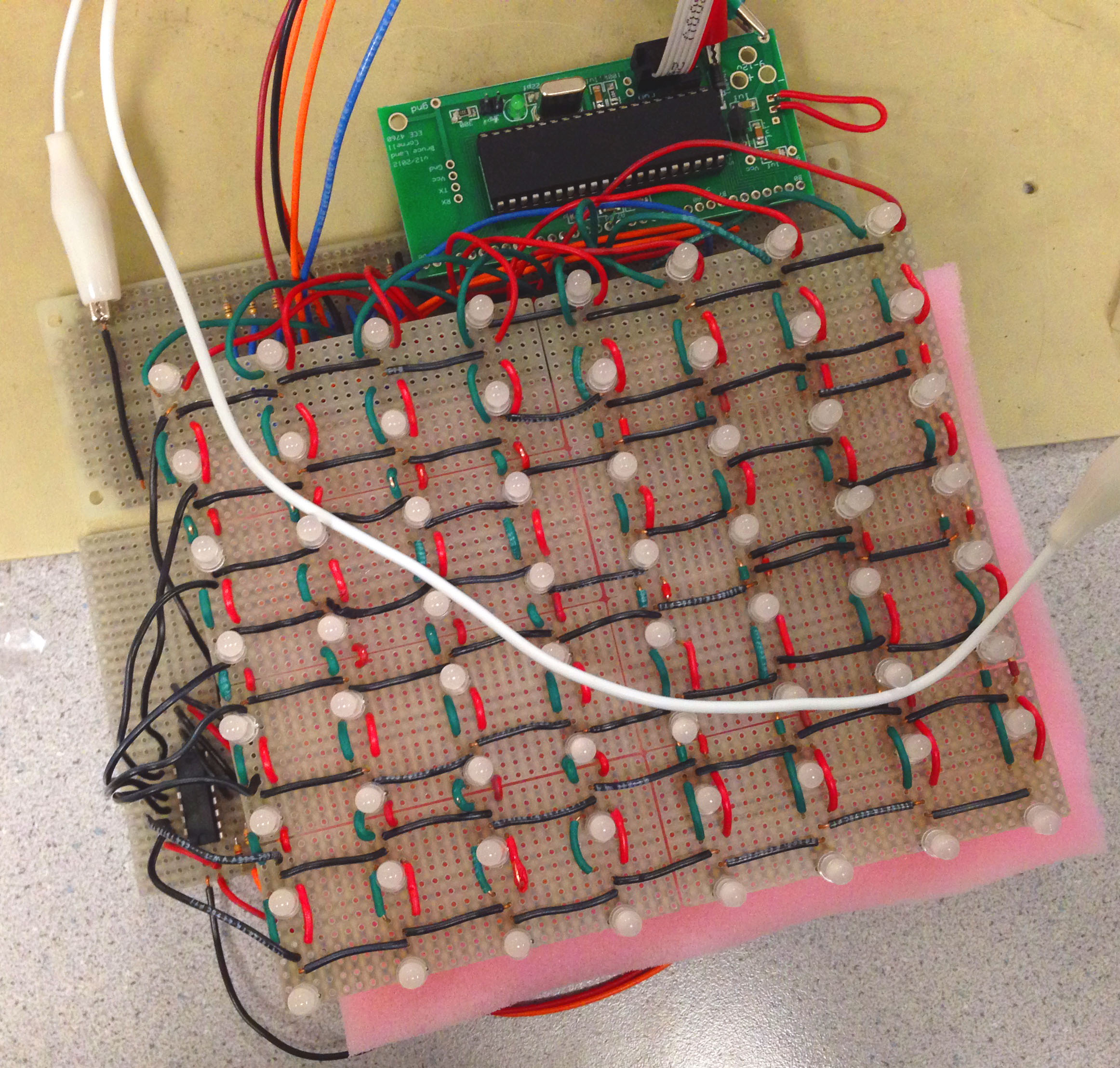
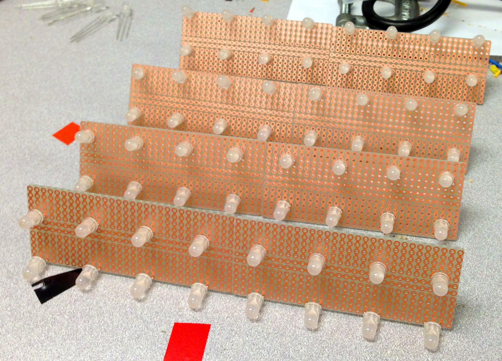
Completely Soldered LED Board
Pin assignment was one of the crucial parts of the design. The Atmel Mega1284 had 32 pins in total with 4 Ports -- A B C and D. We planned to connect each row to the ground periodically while keeping columns sharing the same red cord and green cords. In this case, only one row would be powered because other rows would be open circuits. We also used the 8 pins in Port C for the 8 columns of green LEDs signal, and the 8 pins in Port D for the 8 columns of red LEDs. A complete soldered model was shown above.
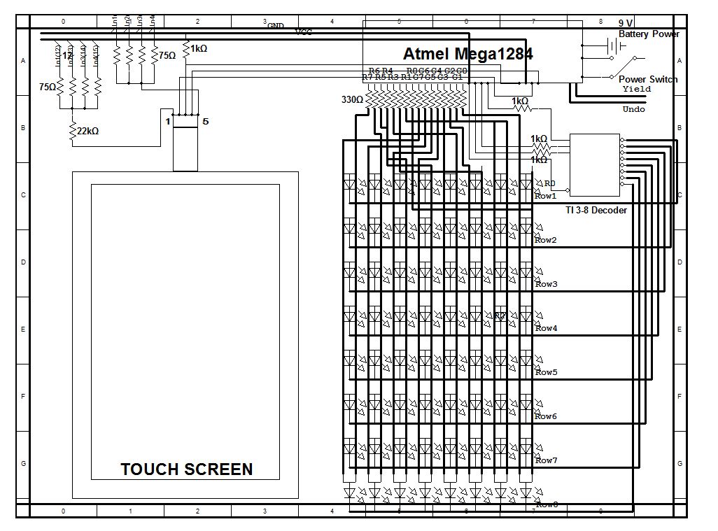
With the fix cost of 16 pins, we could not afford another 8 pins for the row switching, or that would have left us so limited pins for touch screen connections. A 3-to-8 decoder in this case solved our problem sharply. So A5 – A7 were assigned to the decoder pins. The signal from the touch screen goes directly to the A0 pin. B6 and B7 were used to enable the X and Y coordinates detection on the touch screen so we would get an X coordinate and a Y coordinate separately. And lastly, B1 and B2 were used for the pushbuttons. Other port pins were left unconnected. So we used in total 24 pins out of 32 controllable pins. Port Vcc and GND were also used.
16 (LED Power) + 3 (Decoder) + 2 (Touch Screen Enable) + 1 (Touch Screen Signal) + 1 (yield button) + 1 (retract button) = 24Pins
• Logical Structure
There were three parts constituted the majority of the system. They were the MCU, the touch screen, and the LED board. The resistive touch screen was the sensor interface used to sense any touch on the screen, and then output the signal to the MCU.
The MCU then acted like a terminal, which received the signal from the touch screen, and then converted that to digital signals by using Analog to Digital Conversion (ADC). After checking for de-bounce, it then compared the digital value to the pre-set position value to find the corresponding LED that needed to be turned on. The MCU was also responsible to check whether the player was allowed to turn on the pointed LED according to Reversi rules. Every time a new LED was turned on, the MCU would check whether LEDs on the same row or column needed to be flipped according to the rule. If the player pushed the retract button externally, the MCU should react accordingly. The MCU would check which player won by comparing the number of green LEDs and red LEDs. But to trigger the winner check, two consecutive push of the "yield" button was required – both of the players thought there were no other steps they could go. The MCU was also responsible to close and open different rows' circuit each time so that the LEDs could get displayed properly.
The LED board was a regular 8-by-8 Reversi board setup. Although the 8 columns were sharing the same Port C and Port D, there would be only one row connected to ground each time. So we had different buffers for different rows according to row number that the decoder was choosing.
• High Level Design Block
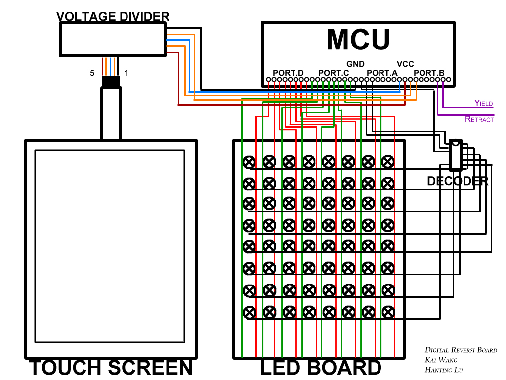
Overall Structure Blocks
• Hardware/Software Tradeoffs
Hardware
Our goal of this project was to provide an intuitive to play and convenient to use product. So we made everything into one box with layer structure where players could only see the LEDs and the board matrix.
We separated the "yield" and "retract" button from the touch screen by placing them with the switch on the side. In this case, players would not be bothered when they were concentrating on the game. In the case that there might be a false detection which would light up the wrong LED, the "retract" button was required because pieces flipped on this digital Reversi board could not be physically retracted. The "yield" button was an indication to the MCU that a player was yielding the chance. And we used battery as the power source for the convenience to carry around.
We decided to use cardboard as the case instead of a steel one because cardboard was much lighter to carry with reliable solid structure.
We chose to connect rows to ground one by one because we could not afford enough pins on the MCU for individual LEDs. Constantly toggle the LEDs would shorten the LED life considerably but it was worth to do it.
Software
The benefit of having a digital Reversi board was that the system would flip the pieces for you by internal calculation. The system would also prevent players from placing the wrong position by simply not lighting the wrong LED even if the player touched the screen position above that. There would be a short delay after the finger touch the screen because of the Touch Screen Debouncing check. This was crucial for correct position detection.
We did not implement the winning check for two reasons. First, checking if there was a winner would involve too many logics, which might slow down other tasks. Second, players would know whether there was any other step they could take; if there was not, both of them would yield the chance. So two consecutive "yield" button pushes was a great external indication of the winning condition check. So the MCU could check the winner after receiving the indication.
We used Port.A and Port.B for both input and output purpose. But we had to declare them as input or output pins when we needed them to perform different functions. For example, we set Port.A as an input port when we wanted to read the signal from the touch screen. As a tradeoff we could not set the row selection. For the same reason, we set Port.B as an output in order to toggle the inputs to the touch screen. Meanwhile the system would be not able to detect external button pushes. The reason was that, pins of an outputting port could not perform in a desire way; we could not get any toggle signals if we put toggling pins and row selection pins all in Port.B.
• Relationship of your design to available IEEE, ISO, ANSI, DIN, and other standards
Due to our design, we did not implement things involved with any specific standard.
• Discuss existing patents, copyrights, and trademarks which are relevant to your project.
One patent we found similar to our design is a led board to play go (patent No.200920120062). Although the method to sense the position is different, there are several concepts overlapped and we do not believe there are any patent opportunity for our design. A further discussion was elaborated in the intellectual property section in Conclusion.
Program/Hardware Design top
• Program Details
Touch Screen Position Detection
Pin 3 (Plane) of the touch screen would output a voltage between 0V to 5V to A0. We programmed the MCU so that it would use the internal-reference analog-to-digital converter (ADC) to convert analog signals to digital signals. We used a multimeter to test the voltage drop across the horizontal and vertical axis on the touch screen. And we got a voltage from 0.8V to 4V in both directions; this corresponded to 40 to 200 after ADC. We evenly distributed the rows and columns so that the first and last rows or columns were at 40 and 200, and others were separated evenly. So in this case, the first row was selected if the ADC value was roughly between 180 and 200, and the last row was roughly between 40 and 60. We went back to do minor adjustments to these values after we soldered all the LEDs on the solder boards.
A Integrated Test Of Touch Screen and LEDs
Touch Screen Debounce
The touch screen was sensitive to pressure. Naturally people would apply an increasing force on the touch screen, and then stabilized at some point. Most times this unstable pressure on the touch screen would light up several LEDs because the varying pressure had caused a range of voltage generated to the pin out. We implemented the debounce technique for the touch screen to prevent the MCU from lighting up unwanted LEDs.
As mentioned above, a touch on the screen involved with an increasing pressure applied. So we came up with a debounce checking condition of detecting whether there was a greater force applied compared to the last maximum force; that is, whether there was a greater voltage value being generated then the maximum voltage so far. If there was, waited until the next check. If there was not, waited until the next check also. But when there was two consecutive voltages that had being generated not greater than the maximum one, we said that the player might have applied his desired pressure on the screen and stabilized it. Only then the MCU would go to the look-up table and search for the corresponding row.
Row Choosing and LED Assignments
Once the power switch was on, the MCU would keep scanning the "red" and "green" buffer in task 1 and outputting values through Port.C and Port.D. Meanwhie, it would also periodically changing the row selecting binary value from 000 to 111, and the decoder would translate that to 0 to 7. The "red" and "green" buffer were all 8-by-8 two-dimensional array. 8 values in a row of the array would ne blasted out through the 8 pins of a port. Specifically, buffer green would be blasting values through Port.C and buffer red would be blasting values through Port.D. So we created a global variable turnColor to indicate the current row number. For example, when the B.5 to B.7 pins outputted 000 (1st row), buffer_red[row][i] and buffer_green[row][i] (i from 0 to 7) would be chosen to be outputted. LEDs in the first row had a chance to be lighted up because only them were connected to the ground.
Reversi rules and program logic
Rules: The common reverse has pieces with color black and white. Because this project implemented the pieces with duel color led which has red and green color led set, in the following discussion two players will be referred to as red and green.
 |
 |
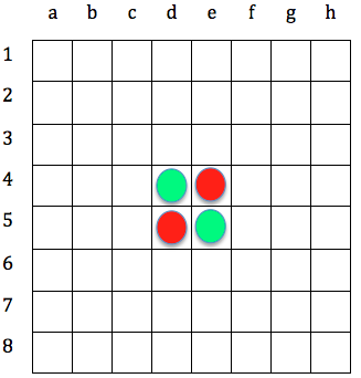
Starting Position |
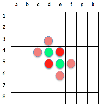
Possible Moves for Red |
Reversi starts with four preset moves on board that the central four squares has two pieces for each player. The initialization of the game is shown above.
Each move must place a piece in such position that there exists at least one straight occupied line (can be horizontal, vertical or diagonal) between the new move and the old piece, which has the same color with the move. Between this line the pieces must all be opponent's pieces (at least one). Figure above on the right illustrates possible moves for red (assuming red move first).
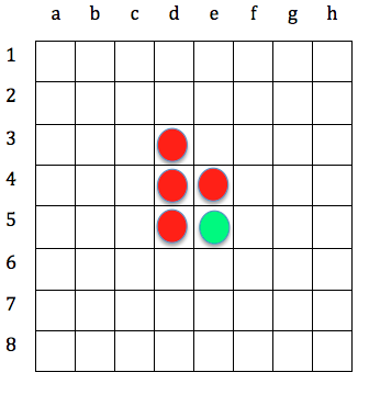
After placing a piece, all the green pieces placed on the line between two red pieces are reversed to green. In other word, a valid move is one where at least one pieces is reversed. For example, if red place a new pieces on 3d, then the situation will become the one shown below.
 |
 |
Situation after red move on 3d |
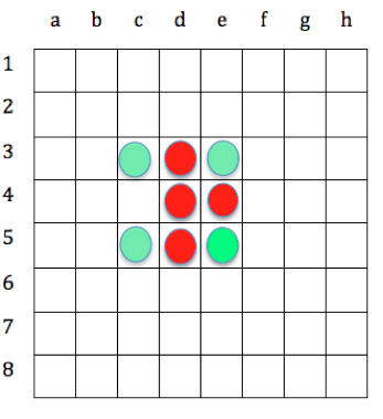
Possible move for green after red move on 3d |
Now green plays. It makes the move under the same rules, which at least reversed one red piece after the new move. All possible move for green after that are shown above on the right.
Players take alternate turns to make move. If one player cannot make a valid move, he or she passes back to the other player. The game ends when neither player can make a valid move. This situation occurs when the board has filled up or when neither player can legally place a piece in any of the remaining squares. Player wins the game if at the end he or she has the most remaining pieces on the board.
Program Logic
To implement Reversi's rule to the program, four 8 * 8 arrays (buffers) are used to save the current and previous situation for red and green pieces on the board. A LED is turned on by set the corresponding buffer a value of 1. Each time a new move occur, the program check the following case to implement the rule:
Is this move made by red or green? (checking the flag) Has the move position already been placed a piece?(check the corresponding buffer) Is there any piece in the straight line (horizontal, vertical and diagonal) has the same color with the current move ? Are the pieces on the line are all opponent's pieces? (at least one)
By doing the process describe above, a valid move can be checked and then the pieces on the line can be reversed to the other color by toggling the input to the corresponding dual color led. To scan the row, column, and diagonal for the current move, the following format is used in the program.
Current move: |
buffer[col][row] |
|---|---|
Pieces on the same row: | buffer[i][row] |
Pieces on the same column: | buffer[col][i] |
Piece on the same diagonal: | buffer[col±i][row±i] |
The following diagram illustrates the same strategy described above:

Flow Chat for implementing Reversi's rule in program
Another separate task in the program execute every 200ms to check if the game is end. To do so, a "pass back" button is implemented in hardware and program. If the button is pushed, then the move is passed back to the other player which in program means that the flag is toggled. If the task detects two consistent pass back button pushed without a new move, then the game is over. The red and green current buffer which has a value of one will be counted and compared, the buffer has more "1" in it means there are more that color's pieces on the board, thus the corresponding player wins the game. The program announces the winner by turn on all that color's LEDs.
In case a move mistake, an "undo" button is implemented in the program. If the button is pushed, the previous value saved in two buffers will be transferred to the current buffer, which means the most recent move is withdrew.
Button Push Debounce
A debounce check of two pushbuttons was required to prevent consecutive retracting or yielding mechanically. So we used the demo code from lab1 to implement a similar debounce check mechanism. This mechanism had 4 states – NoPush, MaybePush, Pushed, MaybeNotPush. The debounce check task would be called constantly to check the push states. A state machine diagram is shown in Figure below.
• Hardware Details
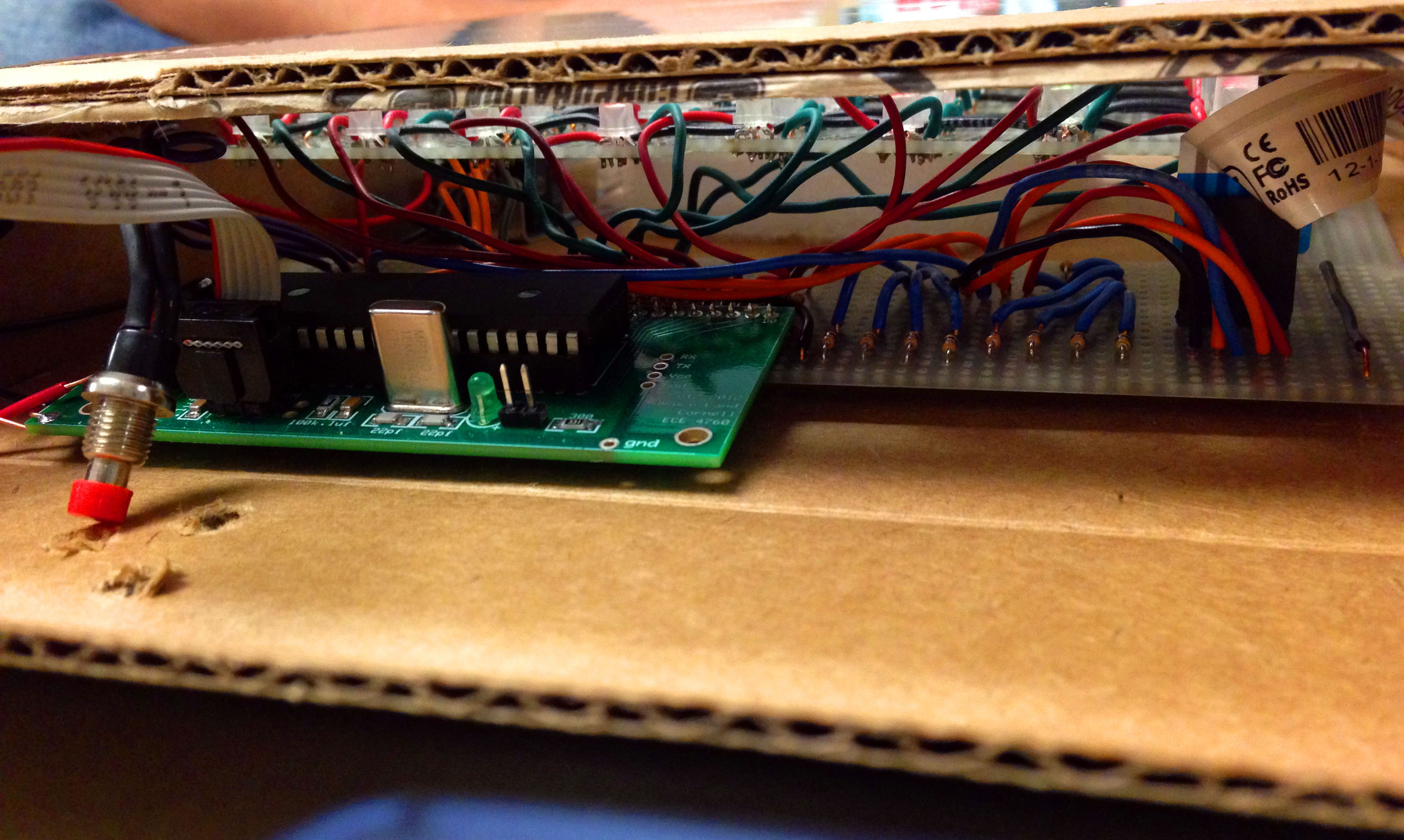
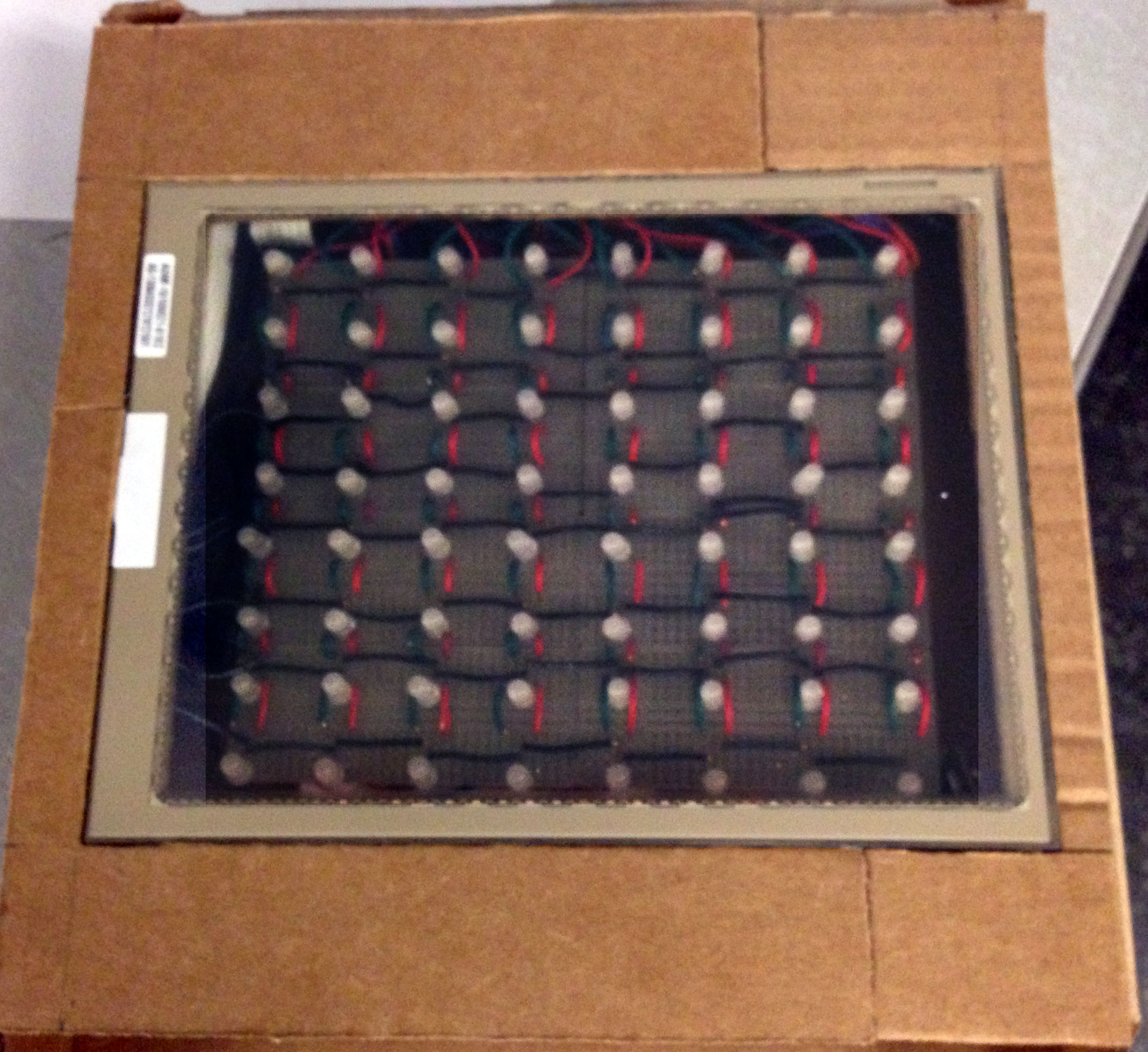
Layered Structure Inside
5-Wire Touch Screen Pin Outs
The touch screen we used could not return the X and Y coordinates at the same time because there was only one output pin from the touch screen, which would return a voltage when the screen is touched. So the only way was to toggle the 2nd and 4th pin on to measure the X and Y voltage separately; when B.6 was 5V, B.7 should be 0V and vice versa. The touch screen connector had 5 pins:
- 1. Upper Right (always GND)
- 2. Lower Right (B.6)
- 3. Plane (output)
- 4. Upper Left (B.7)
- 5. Lower Left (always Vcc)
A graph of the touch screen and its connector is shown below.
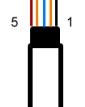
Touch Screen Connector Pin Outs
We chose to always connect Lower Left to 5V and Upper Right to GND, but chose to switch between Lower Right and Upper Left to 5V as to choose between horizontal axis (X) and vertical axis (Y). For example, when we assigned the pins to be 00X11, the upper and lower right sides would have 0V, and the upper and lower left sides would have 5V. In this case, touching the screen more to the left would return a relatively higher voltage to Pin 3 comparing to touching on the right. As we set 00X11 to acquire the row information, we also set 01X01 to acquire the column information – Touching more to the bottom would return a higher voltage to Pin 3 comparing to touching more to the top.
Voltage Divider
We found the touch screen had a ±1V offset when we unit tested components. The reason was that instead of an expected 5 V coming out from PORT B.6 and B.7, the output was slightly below 5 V and a value about 4.3V was detected. The same situation also happened when a 0V was needed from PORT B.6 and B.7, the actual output was about 0.2 V. To solve the problem, we built two voltage divider circuits to the connectors with ground and Vcc. As a result, the input to the touch screen were calibrated to two 4.3V and two 0.2 V. the detail layout of the voltage divider is shown in Appendix.
Touching Sensitivity
At first, we connected Pin 3 of the touch screen connector directly to the MCU Pin A.0. And we sooner discovered that the voltage signal coming out of Pin 3 was very sensitive to the pressure. The over sensitivity bothered us because different people had different touching force, causing a varying range of voltage generated. If we had failed to unify the voltage signal, it would have been extremely hard to predict the true position that had been touched. We later found detailed design schematics from one project done by previous students who also used a touch screen in their design. And we found they connected a 1kΩ resistor in series with the output pin and connected that to the ground. We did the same thing and successfully solve the problem; the output voltage would be stable at a certain value right after a touch, and the voltage would only vary at hundredths even if the pressure kept changing.
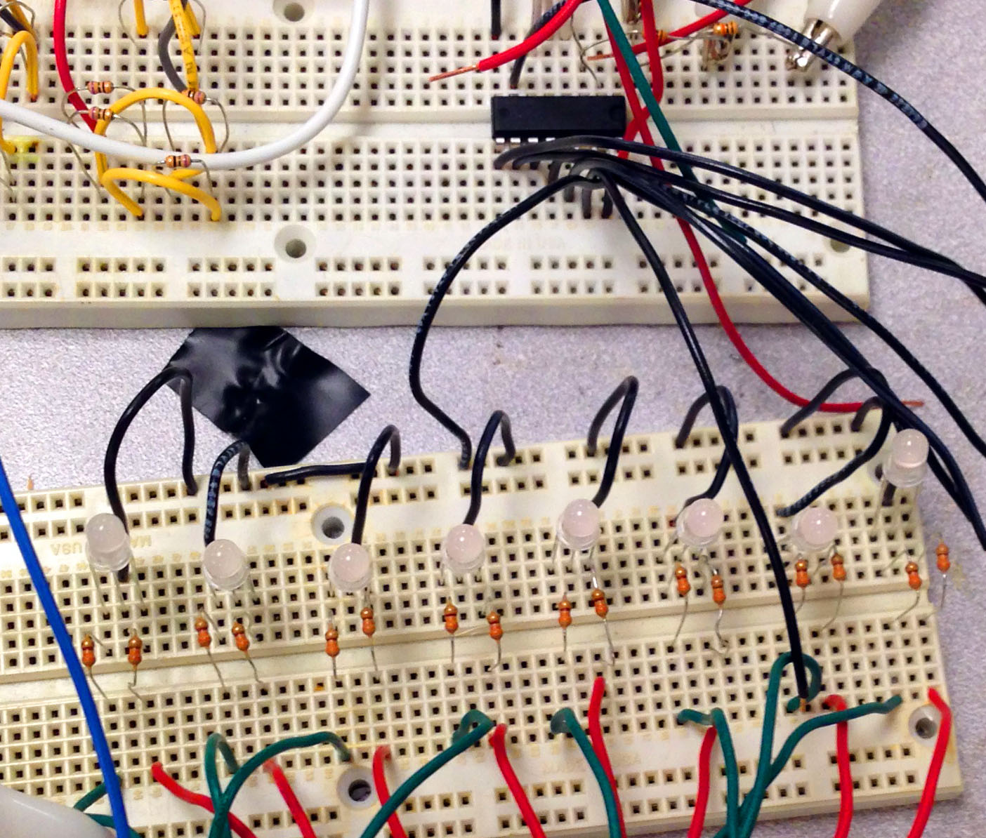
Decoder and LED Parallelism
As we can see from Figure 1, LEDs in a column are sharing the same red and green bus line while LEDs in a row are sharing the same ground line. Another possible approach could be connecting all the LEDs in a row with the same red and green bus while LEDs in a column sharing the same ground. Both ways would work. This design was chosen to save a lot of unnecessary soldering work and also to save pins for other functions. The ground lines and red/green bus should be in this perpendicular structure to ensure that only one row would be enabled at a time, and it was fine for LEDs in a column to share the same red and green bus. We first tested our design on bread boards with columns and rows tested separately. A row lighting test would only involve with one output pin from the decoder. And a column test would involve with all eight pins from the decoder.
 |
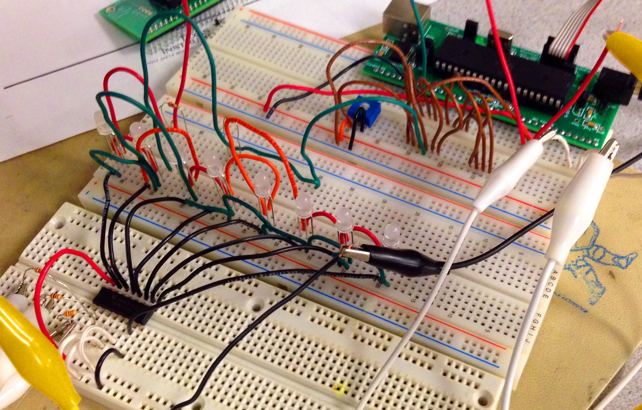 |
Column Switching Test |
Row Switching Test |
 |
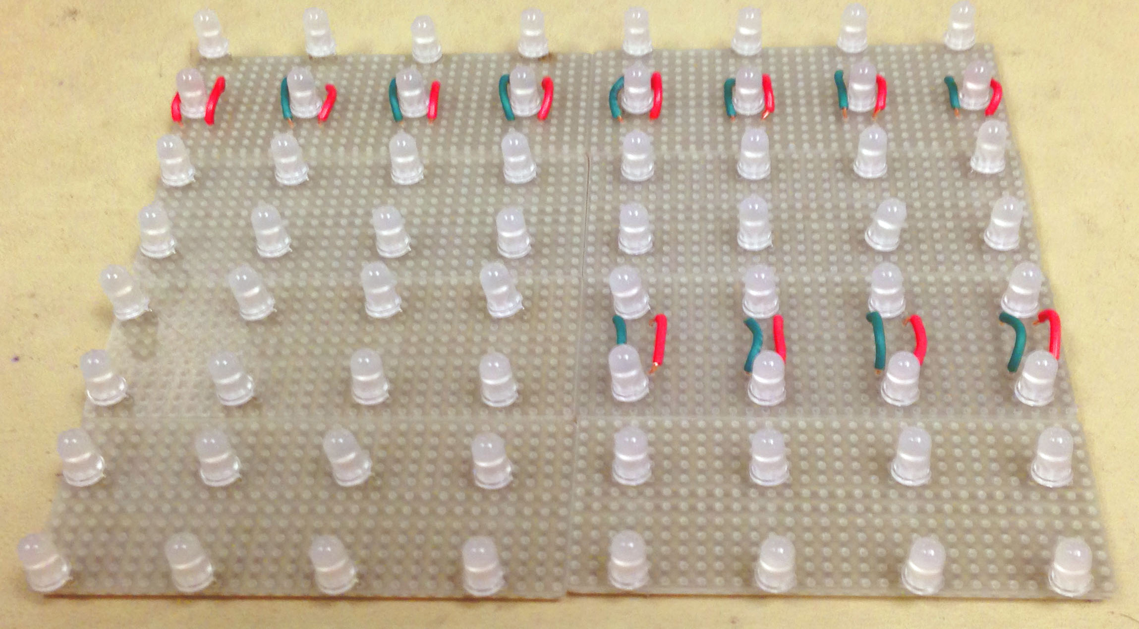 |
Pre-Soldered LED Board |
Soldered LED Board |
• Things you tried which did not work
Pin Assignments
Port.C and Port.D were assigned as output pins for the red and green bus at the very beginning. But we used to choose B.0 to B.2 as our row selection pins, and B.6, B.7 as the toggling inputs to the touch screen. And we planned to connect two pushbutton inputs to A.6 and A.7. The reason was to separate output and input signals so that setting ports to input or output ports would not bother us all the time. But toggling B.6 and B.7 would be interfered by setting B.0 to B.2 even though we used the OR command. So we then moved the toggling pins to A.6 and A.7. And we moved pushbutton detection to B.6 and B.7. In this case, we had to set them to input or output pins each time when we wanted to perform certain functions.
MCU Testing with ECE4760 Lab1 Demo Code
Results top
• Speed of Execution
Virtual timers called all tasks in our program. We did not implement a kernel simply because the system successfully perform what we expected. After being lighted up, the LED would be toggled every 22 ms (45.5Hz). A screen capture of the oscilloscope was shown in Figure below.
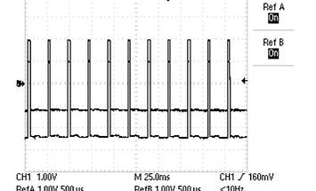
Actual Frequency of the Output to LED
The Reversi rule was taken place almost immediately when a new LED was turned on. Players would not see a significant delay of the system. In this case, they could enjoy the game more.
• Accuracy
We preset the possible LED location by trying out the lowest and highest voltage we could get by touching the screen for both X and Y coordinates. And then we calculated all 64 positions digital value. After soldering all the LEDs on the solder boards, we placed the whole board under the touch screen and tested the preciseness of the position again. The final product had a very precise measurement of the position and could correctly turn on the corresponding LED.
• Safety Enforcement
9 Volt was the highest voltage supplied to the system, which was came from the battery. 9V is a relatively safe voltage to be applied, as human body is a huge resistance. The voltage output from the MCU was 5V, which was also very safe.
In circuit protection circumstances, we connected a 330Ω resistor to each of the pins of Port.C and Port.D to cut down the current draw to the LEDs. 1kΩ resistors were also used to connect A.5 to A.7 in series one for each to protect the decoder. A 10kΩ resistor was connected in series with Pin 3 of the touch screen connector in order to protect the touch screen. And it also helped to quickly stabilize the voltage output.
• Interference with Other People's Designs
Our project did not involve any wireless communication or RF or any type of noise. So there was no interference with other people's designs in any circumstance.
• Usability
Our project was a digital version of Reversi. We designed the project in the hope to create a easy and comfortable experience when people first started trying it out. We avoided ways that might cause even a little confusing. Two people could play together each time. The rule programmed in the system was exactly the same with common Reversi game. As always, this game was suitable for people of all age groups.
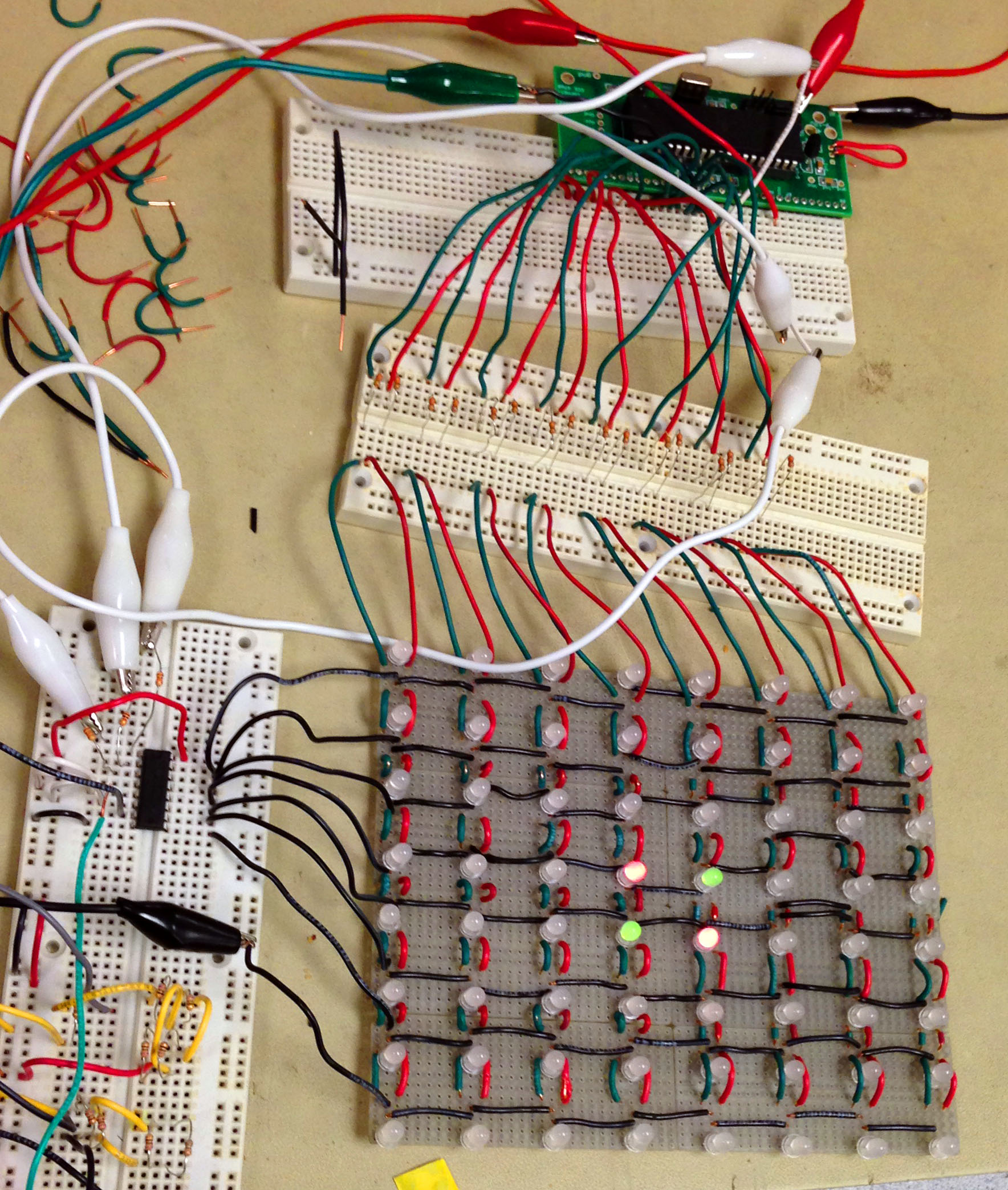
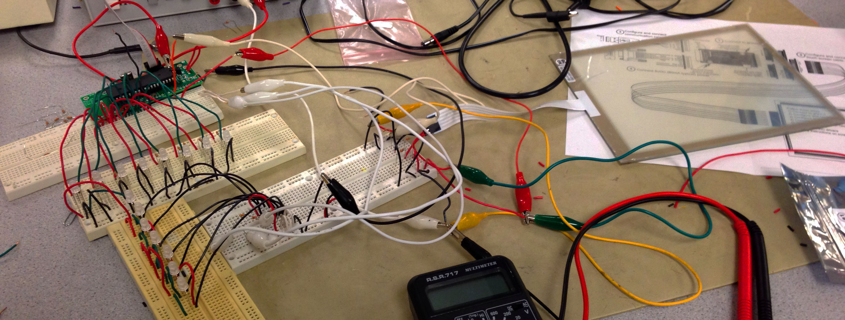
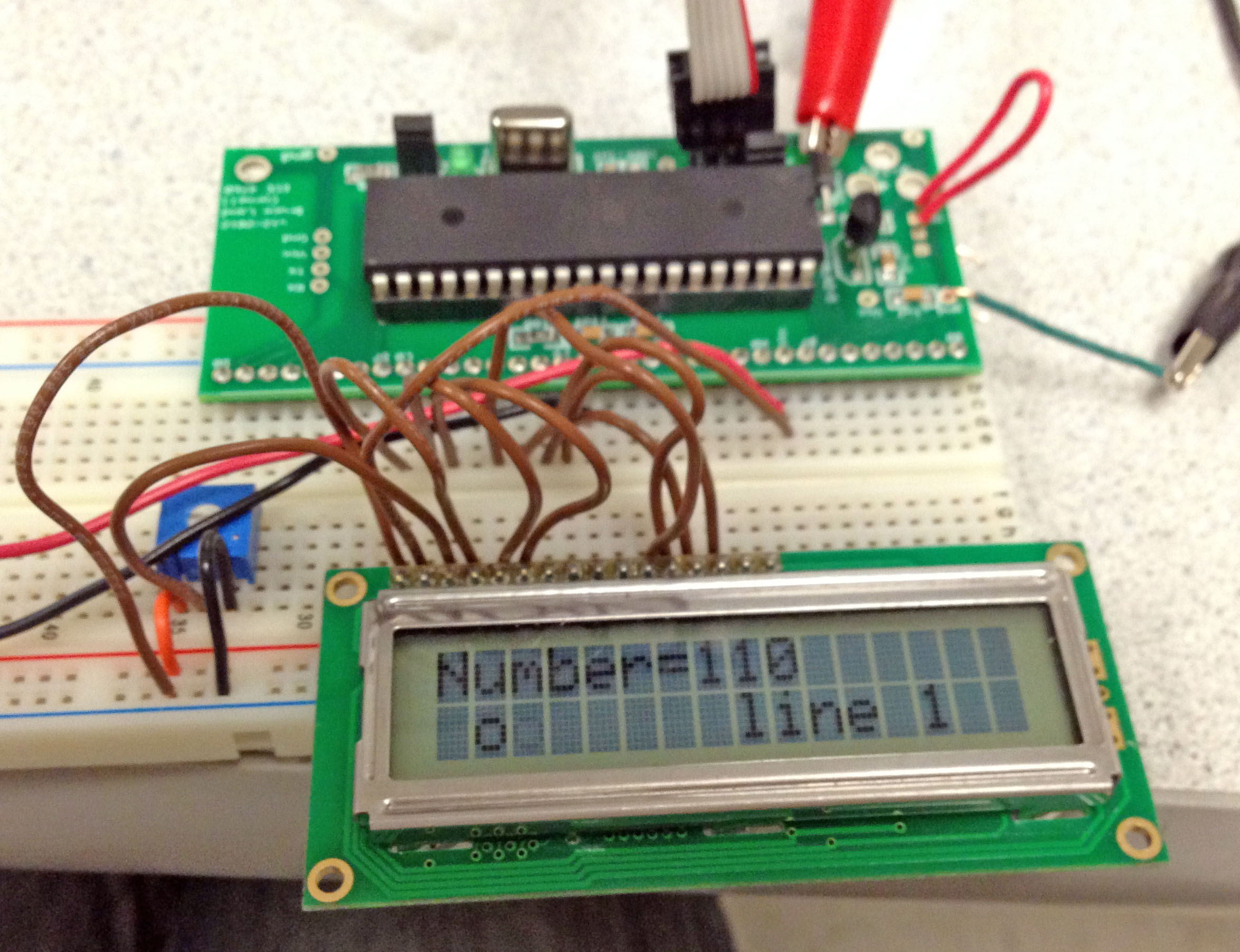
Whole System Working with Separate Parts
Conclusion top
• Results V.S. Expectations
Over all, the project met all expectations. It followed all the rules of Reversi, and had a response time less than one second to make a valid move and reverse pieces. The touchscreen was calibrated to have accurate position output for a push on the screen( ±0.3mm ). Two buttons executed their corresponding function after no more than 0.2 second it being pushed. The final judgment for the winner was quick (less than 0.2 second) and accurate.
For the future design, an LCD may be added to the device to show which player should move and the amount of pieces of each player in real time. Considering the current project has already used all four ports of the microcontroller, adding the LCD feature is doable but PORTs utilization must be redesigned to leave one PORT for LCD.
Another future design could be multiple "undo" push in a single turn. The current project design can only allow the player to undo the move to the last one. By improving the code to better using the memory of the microcontroller, it is possible to undo more than one move in the future.
| Objective | Achieved? |
|---|---|
| Players can turn on the power from external switch | Yes |
| Players can touch the screen and light up the corresponding LED | Yes |
| Some LEDs may be flipped according to the rules | Yes |
| Some LEDs will not be lighted/flipped according to the rules | Yes |
| Can undo for only 1 time | Yes |
| Can yield the chance to the other player | Yes |
| The systen can tell who wins the game | Yes |
• Intellectual Property Considerations
To our knowledge, we did not reuse code from someone else's design. The state machine code is similar to that we used in lab 2 and 4, while the code as a whole was written by ourselves. Our work, however, was built partly upon earlier works especially in using persistence of vision to implement LED matrix. There are also several similar designs such as implementing Backgammon using LED matrix and phototransistor to detect the position. However, our design differs form other works in various way. We made an 8*8 LED matrix and implemented the Reversi logic on it with the position detection by touchscreen. We believe we have not violated any existing patents.
However, one patent we found similar to our design is a led board to play go (patent No.200920120062). Although the method to sense the position is different, there are several concepts overlapped. We treated this final project design as a good practice on a microcontroller. We applied knowledge we learned from this course and reflected on our project. We do not plan to apply a patent for our project.
We ordered one sample touch screen from Bergquist Company, and they did not ask us to sign non-disclosure agreement.
• Ethical Considerations
During the whole process for the project design, our behaviors were consistent with the IEEE code of Ethics.
We consistently checked if any of our devices are overloaded or distributed large amounts of hear in order to avoid the possibility to causing electrical explosions. We carefully soldering every component and place the solder iron back to the stand immediately after finishing soldering. By doing so, we took every precaution to avoid causing others physical harm.(IEEE Code of Ethics, code 9)
The report and write-up related to this project are all based on statics we recorded during project building and experimenting. Anybody who used the same scheme and comments referred in this report should get the same results as we did. We are honest and realistic in sating claims or estimates based on available data. (IEEE Code of Ethics, code 3)
Through the design, building, and packaging the project, we improved our understand about how to implement a led matrix using persistent of version, the technology of resistance touch screen and so on. These technologies have an appropriate application on images generating projects and position sensing projects. (IEEE Code of Ethics, code 5)
We ensured that we only use the technologies that we have been trained during our education. We well understand the AVR and Atmega 1284 after previous labs and read the datasheet and paper from other's research provided us a good understanding about led matrix and touch screen. (IEEE Code of Ethics, code 6)
We acknowledge and previous findings and reference of others and also accepted suggestion and criticism form professor and classmates. (IEEE Code of Ethics ,7) We treat all our peers fairly regardless of race, religion, gender, disability, age, or national origin (IEEE Code of Ethics, code 8) and communicate our experience on soldering, components finding and tried to provide our experience on effect way to using PORTs to other groups. (IEEE Code of Ethics, code 10)
Finally, we ensured that our project did not infringe on the safety, health, and welfare of the community of environment (IEEE Code of Ethics, 1). There were no conflicts of interest (IEEE Code of Ethics, 2) or bribery (IEEE Code of Ethics, 4) throughout this project design.
• Legal Considerations
All the components we used in this project were under safe power supply. The project was also taken the tough taste to ensure its stability. The project device is safe for every user to enjoy their time playing reversi.
Appendices top
A. Detailed Schematics
B. Cost details with all part numbers, vendors, and their price (PDF)
| Item | Vendor | Unit Cost | Quantity | Subtotal Cost |
|---|---|---|---|---|
| 9V Battery | ECE 4760 Lab | $2.50 | 1 | $2.50 |
| Atmel Mega1284 | ECE 4760 Lab | $5.00 | 1 | $5.00 |
| Bergquist 5-wire Resistive Touch Screen | Bergquist Co. P/N:BER251-ND, Sample | $0.00 | 1 | $0.00 |
| Bicolor LED, green and red, Through Hole | DigiKey, P/N160-1057-ND | $0.411 | 64 | $26.304 |
| Power Switch | ECE 4760 Lab | $0.00 | 1 | $0.00 |
| Red Push Button | ECE 4760 Lab | $0.00 | 2 | $0.00 |
| Small Solder Board(2'') | ECE 4760 Lab | $1.00 | 9 | $9.00 |
| Solder Board(6'') | ECE 4760 Lab | $2.50 | 1 | $2.50 |
| TI Line 3:8 Decoder, Through Hole | DigiKey, P/N:296-2091-5-ND | $1.31 | 1 | $1.31 |
| Total | $46.614 |
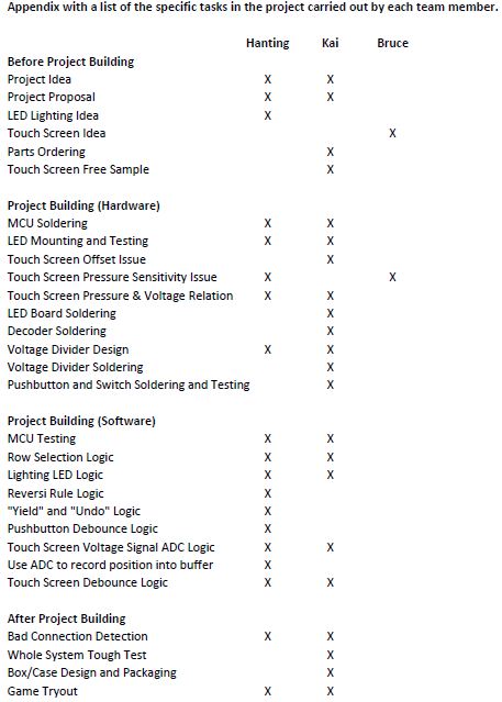
C. List of the specific tasks in the project carried out by each team member
D. Reference
Data sheets
- Atmel mega1284 Microcontroller
- Bergquist Touch Screen 8.4" 5-Wire Resistive Sensor, P/N 499265
- LITEON Bicolor LED, P/N 160-1057-ND
- Texas Instrument 3-8 decoder
Vendors
Background Info
Code/designs borrowed from others
E. Source Code
Acknowledgements top
We would like to thank Professor Bruce Land for his thorough and insightful guidance in ECE 4760, and for all the suggestion and assistance provided to our project design. We would also like to extend our gratitude to all the TAs' hard work for the entire semester especially Annie Dai (wd65) who assisted us in every lab throughout the semester.
Further, we would like to express our gratitude to the Bergquist Company Touchscreen Division for their generous donation of the sample touchscreen.
About Us top
 |
Hanting Lu
M.Eng Student, 2013
Electrical and Computer Engineering
Interests:
Embedded System, Computer Architecture, Control System |
 |
Kai Wang
Bachelor Candidate, 2014
Electrical and Computer Engineering
Interests:
Embedded System, Autonomous System, Robots, System Testing |