Our final project is to build a multifunctional music box. This music box can generate different songs in different instrument sounds, i.e. piano, organ, by FM synthesis. The theme and harmony are in two different channels. Besides, the music box can also be electrical piano by which users can play their own music, the piano keyboard is implemented by infrared emitter and light sensor. There is also tutorial function which can teach users to play a sound stored in music box. Distance sensor to control music box switch.
High Level Design top
Rationale and Inspiration
Music synthesis is always a very interesting and enjoyable project of Microcontroller. Inspired by Lab 2 and Bruce’s random music box, we want to expend the basic function of traditional music box to a multi-function music box.
Traditional music box often just has one song to play which lacks of user interaction. What we do in the final project is let users to choose the music and the instrument they like. Apart from that, users can even play their own music by our friendly user interface. The music box can also teach user to play a simple song. Our music box is very suitable for children to gain a basic interest in music.
Background Math
The distance sensor is the switch of music box. The output of the distance sensor is analog signal sent to Port A0. MCU get the result of ADC converter, comparing it with the default threshold. To ensure the ADC could sample fast enough to obtain the distance information with minimal latency, we set timer2 as compare match mode and use compare match ISR to get the ADC result. The interrupt time interval of timer2 is:
Remark:
- OCR2A=249, then timer2 has 250 sticks.
- The clock rate of MCU is 16MHz
- Prescalar of timer2 is set to 64, the time interval for timer2 stick is
We add time1 as time record variable and increase time1 once in ISR, checking the ADC value when time1 equals to 250. So the sample rate of distance sensor is 250ms.
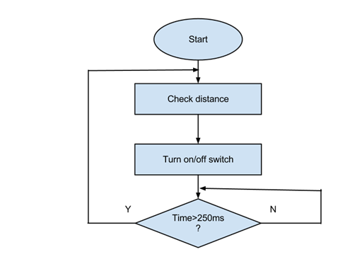
Figure 1. Chart flow of distance sensor
Logic Structure
At the beginning, our user control are combined by distance sensor and user interface. Distance sensor reflects the distance between music box and user, music box will only produce music when distance is shorter than the threshold. Then the switch button can change the work mode. There are two work modes:
(1) Music Play Mode
Under this mode, the music box will automatically play the songs stored in the Microcontroller. The user interface made by infrared emitter and light sensor can change different parameter of the song including song itself, instrument and harmony. There is also a line as hold button. When hold function is chosen, even the distance between user and music box are longer than threshold, the music will keep playing. This function enables users to listen the music and do anything else at the same time.
(2) Play Electrical Piano Mode
Users can also change to Play Electrical Piano Mode to play their own music. It can generate the sound of basic range including 12 notes from C4 to B4. There are also a tutorial function which can teach users to play a simply song. The LED on each note will light up in order, by following this play order, users can play the song.
The following is the Logic Block Diagram of multi-functional music box:
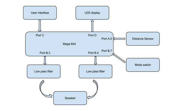
Figure 2. Block Diagram
Hardware and Software trade off
1. Hardware:
To simple the process of signal result of distance sensor and increase accuracy, it’s better to use digital distance sensor instead of analog one. However, digital distance sensor costs much more than analog one and digital sensor need 8 ports on Microcontroller to receive the result. Besides, in our final project, accuracy doesn’t affect too much, so we decides to use analog distance sensor and use internal ADC of Microcontroller Mega1284 to realize AD converter.Software:
2. Software:
The main trade off of software is the choice of sound synthesis algorithm. Karplus-Strong physical synthesis is very suitable for microcontroller because of its simple algorithm, besides it can produce the sound a real instrument, however, it can only generate several notes since performance will be affected a lot by high frequency. FM synthesis may not generate sound as real as Karplus-Strong physical synthesis, but its frequency range is much larger which meets the requirements to play a whole song rather than just several notes. After serious consideration, we end up use FM synthesis.
Existing Patents/Copy Rights/Trademarks
Music synthesis is a very popular project on microcontroller since its implementation is very simple and feasible. There are projects based on different sound synthesis algorithm and the focuses of these projects vary a lot. Our project focus is to produce a multi-functional music box to enhance user experience. With infrared emitter and light sensor, user can control the music box by touch screen like interface. Apart from that, combining song play and piano play together with different mode and instruments will bring more fun and provide more personalization options.
Some projects may similar to our project, but we don’t infringe on other copy rights or intellectual property, as we did not consult other projects for choosing a particular implementation method and we have no intention of patenting our design.
Hardware Design top
In the final project, there are four main parts of the hardware design. First part is the infrared detector circuit and one push button as our user interface. Second part the distance detector circuit as the main switch of the system. The third part is PWM design in the MCU to generate the music box sound. The last part is 8 led to shown the status of the system. Below is the block diagram of the system. We will detailed elaborate these in the following.
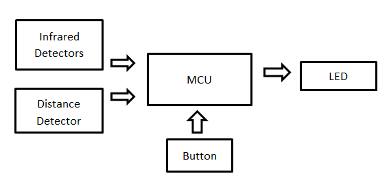
Figure 3. Hardware Block
Infrared detector circuit
We use eight infrared emitters to irradiate directly on eight phototransistors, so that it can detect when fingers are between them and generate a sinc on the waveform.
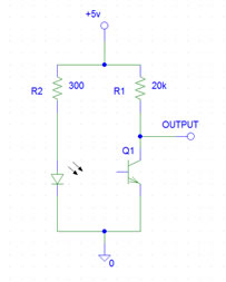
Figure 4. Infrared emitter and Light sensor
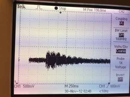
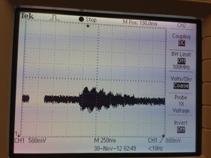
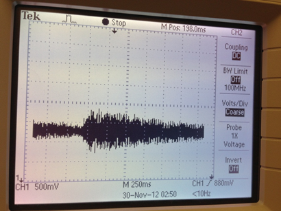
Using the circuit of Figure 4, the voltage of output will be lower when conducting the base and emitter of the phototransistor. So when the finger keeps moving, the waveform is shown in Figure 5.
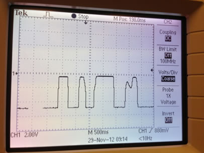
Figure 5. Output of light sensor
To transform the waveform to a square sinc wave so that the MCU can detect pulse more easily. We use a comparator circuit as below.
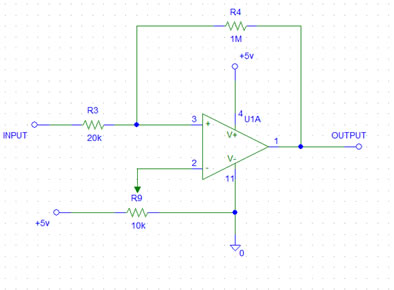
Figure 6. Comparator circuit
When the voltage of pin.3 is higher than the voltage of pin.2, the pin.1 output 5 volt. When the voltage gets lower, and becomes lower than the pin.2, the pin.1 output zero.
With the 1M resistor set between the pin.1 and pin.3, there will be a little amount of positive feedback add to the pin.3. So the waveform of pin.3 will lag behind a little. This lagging behind will reduce the effect of noise on the waveform which may cause the output square wave unstable.
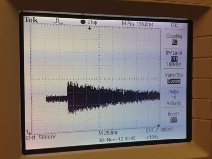
The final waveform that transmits to the MCU is as follow:
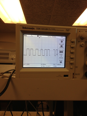
Figure 7
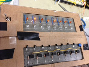
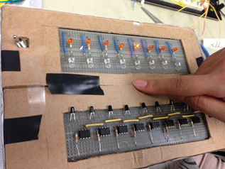
Here is the final board of this part of the circuit we soldered:
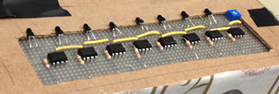
Figure 8
PWM
To generate music sound by PWM, we set timer0 run as full rate and turn off overflow ISR to turn on fast PWM, OC0A output and OC0B output. The initialization set of PWM is 16 microsecond per PWM cycle sample time.
In final project, we use two channel of PWM. The first one we used (OCR0A) is to generate the theme of the song at B3 port while the second one (OCR0B) which comes out at B4 port reflects the harmony of the song. These two PWM are put into the two channels of the speaker after low-pass filter.
Low-pass filter
A low pass filter is needed to connect to the Port B3 (OC0A) and Port B4(OC0B) so that we can filter most of the wave of high speed PWM-based D/A signal and receive a sine wave based on the appropriate PWM output.
We need a resistor that isn’t bigger than the input resistance of the speaker audio input (10 kohm), but isn’t too small that can load the port pin.
The RC time should between 2 to 10 times period of PWM. But we don’t want the RC become too big that the low pass filter will attenuate the bust frequency (Fout) we made:
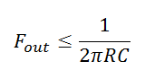
With these conditions, we chose our C to be 20nF and R to be 5Kohm. The Circuit shown in Figure 9:
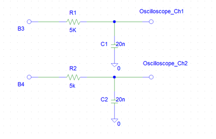
Figure 9
Voltage translation was implemented using simple resistive dividers. The values of the resistors were selected to be small in order to reduce the RC time constant of the translation. This was necessary in order to cleanly level shift the high frequency clock signal without distortion.
To test the read functionality of the Flash memory, a short segment of code was written to send a command from the microcontroller to read the memory chip manufacturer’s ID. To test the erase and write functionalities, a sector erase followed by a page write command were sent to the chip to store data. A data read command was then issued to verify that the contents of the memory were correct.
Speaker wiring
We need two small clips to make this connection between the speaker audio plug (shown Figure 10) and the circuit. The output of the RC circuit will transmit the chirp signal to the speaker by connect with Chanel1 or Chanel2 through the clip. The other clip should connect the ground to ground.
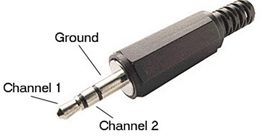
Figure 10
Distance detection circuit
We designed a distance detection module using Sharp IR Ranger. If user come close to our music box (we set this value to 50cm), the music box begins to work under default mode. And if user walks away from the box, it will pause automatically until someone come close again.
The sensor we used for our music box is Sharp IR Ranger (part number: GP2Y0A21YK). It is a kind of wide-angel (Detection Area Diameter: 12cm) distance measurement sensor. It can take a continuous distance reading and outputs analog voltage (corresponding range is from 10cm to 80cm). This measurement range is practical considering the common scenario we are playing with the music box.
There are the key features of the sensor:
Table 1 GP2Y0A21YK Work Requirement[1]
Output type |
Analog |
Supply voltage |
4.5V to 5.5V |
LED pulse cycle duration |
32 ms |
Typical response time |
39 ms |
Typical start up delay |
44 ms |
Average current consumption |
30 mA |
Detection Area Diameter |
12 cm |
Table 2 GP2Y0A21YK Parameter[1]
PARAMETER |
SYMBOL |
CONDITIONS |
MIN. |
TYP. |
MAX. |
UNIT |
NOTES |
Measuring Distance Range |
ΔL |
10 |
- |
80 |
cm |
1,2 |
|
Output Terminal Voltage |
Vo |
L= 80cm |
0.25 |
0.4 |
0.55 |
V |
1,2 |
Output Voltage Difference |
ΔVo |
Output change at ΔL(80cm-10cm) |
1.65 |
1.9 |
2.15 |
V |
1,2 |
Average Supply Current |
Icc |
L= 80cm |
- |
30 |
40 |
mA |
1,2 |
Note: L = Distance to reflective object
According to these specifications of the sensor, we are sure that work environment of the sensor can be satisfied perfectly and it won’t do any harm to the main part of circuit. We don’t have any requirements for the response time of the sensor and 39ms is already fast enough.
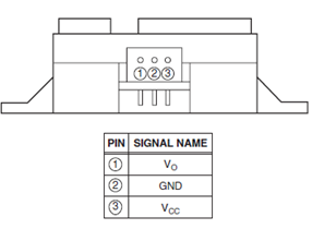
Figure 11[1]
In the distance detection module, we should connect it with the ADC inside MCU. The hardware design is as follows:
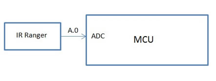
Figure 12
Connect the output (according to pinout diagram shown above, Vo is the output) of IR Ranger to A.0 port of the MCU. There is no extra component for this module.
Software Design top
Sound synthesis
There are different ways to synthesis sound, the most common ways are Karplus-Strong physical synthesis and FM synthesis. We tried both to synthesis the sound. Karplus-Strong physical synthesis is very suitable for microcontroller because of its simple algorithm, besides it can produce the sound a real instrument, however, it can only generate several notes since performance will be affected a lot by high frequency. Unlike Karplus-Strong, FM synthesis combines Direct Digital Synthesis(DDS) and FM modulation to produce sine wave with wider range of frequency, which meet us requirements to generate music. We end up use FM synthesis.
1. Direct Digital Synthesis (DDS)
DDS can generate pure sine wave with different frequency by producing time-vary waveform. In the final project, the phase accumulator is set as 16-bit register. The higher 8 bits are used as the phase register for increment and the lower 8 bits are for sine table index. The sine table is initialized in main function. We produce base frequency of FM modulation in timer1 ISR[3].
The output frequency can be determined by changing the increment value in DDS. Since the output frequency is related to the time it takes to overflow the 16-bit register. The formula is shown below:
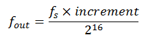
In this project, we set OCR1A equals to 1999 sticks. That is, timer 1 sample rate is 8000 Hz or 125 microseconds. Since, then:
![]()
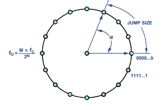
Figure 13. Phase Increment in DDS[3]
2. FM Synthesis
Frequency modulation (FM) reflects information on the carrier wave by varying instantaneous frequency. Commonly, there are two kinds of FM---PM and AM. Here, we use PM to realize FM synthesis.
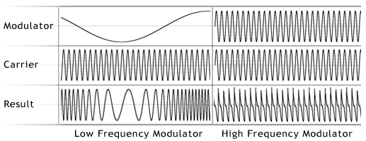
Figure 14. FM modulation[4]
In FM synthesis, the timbre of a simple waveform is changed by FM modulation with a modulating frequency that is also in the range of the timbre. In which way, the more complex waveform generated by FM synthesis will have different timbre.
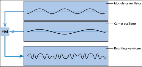
Figure 15. FM synthesis[5]
The formula of FM synthesis used is: Remark: 1) is the modulating envelope which is a waveform combining exponential rise and exponential decay. It can be described as: A controls the peak amplitude of output, and control the increasing speed of rise phase and decreasing speed of fall phase. 2) is the base frequency of the sound we want to generated. 3) is amplitude of FM modulation, is decay parameter to control the decay speed. is carrier frequency. When sound is plucked, we set the initial values to all control parameters. Different voices can be added together to OCR0A. 3. Timbre In FM synthesis, we can change the base frequency, rise speed, fall speed, decay speed and depth to control the timbre of different sounds. Then we can use FM synthesis to simulate different instruments. Some example parameter settings are shown below: Table 3 Parameter Setting[6] In our final project, we create four kinds of sounds to play different kinds of music. These parameters are tested first by matlab, then applied in to final project. 4. Note Generation By defining different notes to different frequency, we can generate different notes. The notes in basic range are shown in the following table: Table 4 Note-Frequency Remark: full table 5. Song Generation Song is a sequence of notes and each note has its own tempo. We store the note sequence in a table and create the index to indicate the current note. There is also a corresponding table to indicate the beat for each note. The indexes for both tables will be increased once when the beat ends for the current note. Increase variable time in Timer1 ISR to record the time interval. By comparing the time and beat for each note, we can control the tempo of the music. That is, when time is multiples of the value of tempo[index], index increases one and changes to the next note. notes[62]={E4,E4,F4,G4,G4,F4,E4,D4,C4,C4,D4,E4,E4, D4,D4,E4,E4,F4,G4,G4,F4,E4,D4,C4,C4,D4,E4,D4,C4, C4,D4,D4,E4,C4,D4,E4,F4,E4,C4,D4,E4,F4,E4,D4,C4, D4,G3,E4,E4,F4,G4,G4,F4,E4,D4,C4,C4,D4,E4,D4,C4,C4}; tempo[62]={0x07ff,0x07ff,0x07ff,0x07ff,0x07ff,0x07ff,0x07ff,0x07ff,0x07ff,0x07ff,0x07ff,0x07ff, 0x0fff,0x07ff,0x0fff,0x07ff,0x07ff,0x07ff,0x07ff,0x07ff,0x07ff,0x07ff,0x07ff,0x07ff,0x07ff,0x07ff, 0x07ff,0x0fff,0x07ff,0x0fff,0x07ff,0x07ff,0x07ff,0x07ff,0x07ff,0x03ff,0x03ff,0x07ff,0x07ff,0x07ff, 0x03ff,0x03ff,0x07ff,0x07ff,0x07ff,0x07ff,0x0fff,0x07ff,0x07ff,0x07ff,0x07ff,0x07ff,0x07ff,0x07ff, 0x07ff,0x07ff,0x07ff,0x07ff,0x07ff,0x0fff,0x07ff,0x0fff}; 6. Theme and Harmony In our final project, theme and harmony of the one song will come out in two different channels of the speaker to make a better music for user. To implement this function, we make use of the second PWM of timer0 and put the sound to OCR0B. The harmony uses its own note sequence and temp. For “Ode of Joy”, the tempo is the same while note sequence changes to: notes_harmony[62]={C4,C4,D4,E4,E4,D4,C4,B3,G3,G3,B3,C4,C4,B3,B3,C4,C4,D4,E4,E4,D4, C4,B3,G3,G3,B3,C4,B3,G3,G3,B3,B3,C4,G3,B3,C4,D4,C4,G3,B3,C4,D4,B3,B3,A3,A3,G3,C4, C4,D4,E4,E4,D4,C4,B3,G3,G3,B3,C4,B3,G3,G3}; The user interface we designed can allow users have two modes of using the music box. First one is music mode which has three songs and four kinds of instrument that users can choose from. Another mode is play mode. Users can play the key they want by 8 phototransistors. The two modes are switched by a button on the main board. figure 16. Music mode figure 17. Play mode 1) Music mode In the music mode, the 4 phototransistors on the left are choosing which instrument to play the song. When certain instrument is chosen, the led corresponding to the phototransistor will be turned on so that the users can easily see the status of the music box. There are two songs can be selected. Whenever the user slides the switch phototransistor, the music box will change to the other song and start from the beginning. The music box can generate an accompany tone to improve the sound of the music. However, with the accompany tone, the music may heard different among each of the instrument. So user can choose whether or not to choose an accompany tone to play in the music. Since the main switch of the music box is controlled by a distance sensor, we designed a hold function. After user choosing the song and instrument, with slide the hold phototransistor, the music box won’t turn off if user is moving away. This function is designed for the play mode and will discuss specifically in the next section. 2) Play mode Under the play mode, the users can play total 13 keys by sliding the 8 phototransistors. By sliding each of the single phototransistors, we can hear 8 different keys from C5 to C4. Besides, we can also play five more key s(Cs4,Ds4,Fs4,Gs4,As4) by sliding two of the phototransistors at the same time. The layout of this user interface is similar to one scale of the piano keyboard shown as below. figure 18 To achieve this function, we uses a unique state machine combined with a debounce function in this system. This state machine has completely two loops to follow according to the situation of which phototransistor has been slide. If one of the single phototransistor has been chosen, the condition is like this: Since output signal of distance sensor is directly sent to input of internal ADC of Microcontroller (Port A.0), we use ISR of timer2 to check the result of ADC. The time base of timer2 is 1 msec. By modifying the example code of ECE4760 lab1 given by Bruce Land, We set OCR2A = 249 to set the compare register to 250 time ticks and TCCR2B= 3 to set prescalar of timer2 as 64. 250*64/16M =1msec. Then we can easily adjust the value of t2 to decide how many milliseconds we check the ADC output. In this final project, we achieved the goal and successfully built the multifunctional music box. It has four kinds of instrument and two kinds of mode- music mode and play mode. Table 5 Parameter setting in our project
Figure 19. The sine wave of the timbre of bell Figure 20. The sine wave of the timbre of electrical piano
Figure 21. The sine wave of the timbre of organ Figure 22. The sine wave of the timbre of machine We can see that the waveform that generated by the MCU is clear and hear similar to the sound that generated by the actual instruments. The sound is synchronize with the system speed and no delay can be heard during the system is working. For the power part, we use 4 AAA batteries to power up the whole system. The current that flow through the system is 0.02 A (shown as Figure 3.5).Since one single AAA battery has the capacity of 1000-1200mAh. Our system can work under the batteries power in 5 to 6 hours. The multifunctional music box system was working properly as we expected. The music sound we generated by the MCU is similar to the sound that generated by the actual instruments. For further improvement, we can try to solve the voltage distribution problem so that the speaker can also power up by the system battery, and won’t leave a 3.5mm socket outside the music box. 1) Intellectual property We first came up the idea of building a new version of music box that can play generate random music. But later, we were influenced by a pervious year project(” Auto-Composing Piano”). It was more fun and playable to actual play the key through a music box and using the interface of building by infrared and phototransistors. The code of the DDS and FM synthesis was reconstructed from Bruce Land’s example DSP code. 2) Ethical consideration The multifunctional music box project is consistent with the IEEE Code of Ethics and has nothing danger to the healthy, safety or welfare of the public. We made sure that our project is keeping with the IEEE standards. We followed all the safety procedures in the 4760’s lab and using all the lab equipment properly. We seek, accept and offer honest criticism of technical work and credit all the paper or project that we are referenced or sharing the idea. We also assist colleagues and classmates in their project if they have questions related or not related to our project. As we obtained a lot of help from professors, TAs and other project classmates, we build a webpage and store all the information of our project on that as an open source. Anyone who is interested into our project can modify or reconstruct our work through the website. 3) Legal considerations Our project do not cause harm to anyone and violate to anyone’s intellectual property. Since our project does not associate with any RF related area. We don’t need to take care of the FCC legal restrictions. Cost details: Tasks allocation: We would like to thank Bruce Land and Terry for their help during the whole semester. They provide quite a lot of support and good suggestions to our final project. We also want to thank our friends and classmates who help us whenever we meet with difficult problems. Last but not least, we need to thank Cornell University that makes all this possible.![]()
![]()
main_freq
main_rise
main_fall
FM_freq
FM_depth
FM_decay
Timbre
261
0
6
350
8
5
chime
1000
1
4
50
10
5
rod resonator
600
1
5
150
8
6
electric guitar
261
4
5
261
7
6
bowed string
Note
Frequency
C4
261.63
C#4
277.18
D4
293.66
D#4
311.13
E4
329.63
F4
349.23
F#4
369.99
G4
392.00
G#4
415.30
A4
440.00
A#4
466.16
B4
493.88
The note sequence and tempo for “Ode to Joy”:
User interface
The function of the 4 phototransistors on the right is written as follow, and each of the phototransistor is corresponding to a led to show the status of that phototransistor.
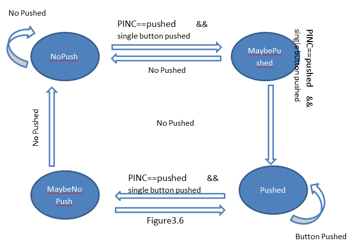
if (PINC==pushed)
Which pushed is the variable that storage the value of which pin is currently being slide. With this determine condition, the state machine will start over when it detects another phototransistor is also being slide at the same time.
However, when the current situation is that already two of the phototransistors are been slide, the condition change to this:
If(PINC!=0)
So, if one of the finger moves away, the state machine will still detect some of the pins on PORTC is using. The user interface won’t pass in the new pushed in to the system. The reason of doing this is when the user is sliding two of the phototransistors. It is impossible to move two fingers away at the same time. So if I only use the condition like if (PINC==pushed) , the user interface will pass in the new pushed and play a unwanted key every time user slide two phototransistors at the same time.
The table of our state machine show as follow: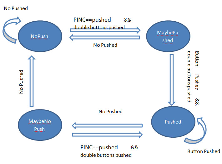
Distance Sensor
Two functions are to initialize the ADC and control the ADC process. One is void initializeADC(void) that sets these parameters of ADC registers ; the other function is unsigned int getAdcValue(void) to get the output of ADC. Because the ADIF indicates whether the ADC is completed and it is set to 1 automatically when ADC finishes, we need to use ADCSRA |= 1<<ADIF to clear ADIF manually in software. More important, this function returns ADCW which stores both high-level 8 bits and low-level 8 bits of ADC output.
In main function, we check the output of ADC which is ADCW returned by unsigned int getAdcValue(void) to compare it with threshold and then set flag. The flag indicates whether the music should be paused or kept playing.
The value of threshold is adjusted for several times by keep trying how close the people walk in can trigger the music. The longest distance is about 50cm.
Results top
At first, we planned to synthesis the real sound of piano, however, due to its special sound principle, we give up in the end. Unlike ordinary string instrument, each piano key hits three strings at the same time, each string has slightly different with other strings. The most important part of tuning piano is to make three strings sound as one note.
When adding three strings to produce the sound of piano, it’s very hard to make three strings sound as one since there will be small time different even when the parameters of three strings are totally the same, not to mention when they are different, even slightly.
In the end, we use one string to synthesis the sound of electrical piano which is much easier to achieve. Here is the attribute of FM synthesis we are choosing.
main_freq
main_rise
main_fall
FM_freq
FM_depth
FM_decay
Timbre
300
1
6
1000
8
5
bell
500
1
4
1500
7
3
electrical piano
500
2
4
1500
11
6
organ
1440
1
5
600
6
4
machine
Conclusions top
We are honest and realistic in stating claims and also in making sure all the calculation and estimates are based on available data. All of our periods of interrupt routine are calculated out by need. And we compare our result with the matlab example precisely to make sure to quality of the sound that MCU generated. Appendix top
A. Source Code and Audio file
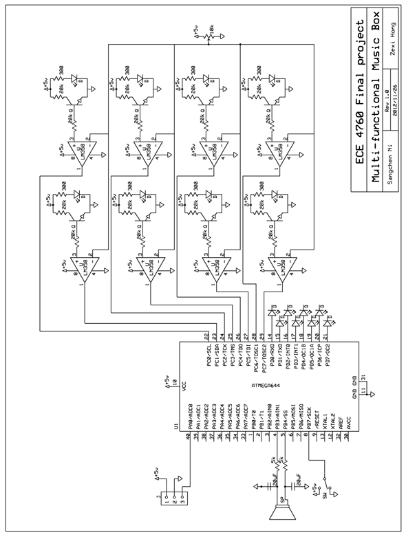
B. Schematic
C. Cost and Allocation
Name
Price
Quantity
Total price
Vendors
White board
$6
1
$6
4760 LAB
Bread board
$2.5
2
$5
4760 LAB
Distance sensor
$14
1
$14
Acroname
Mega 1284
$5
1
$5
4760 LAB
Custom board
$4
1
$4
4760 LAB
Speaker
$0
1
$0
4760 LAB
Flat jumper
$1
20
$20
4760 LAB
Switch
$0
1
$0
4760 LAB
Resistor
$0
--
$0
4760 LAB
Capacitor
$0
--
$0
4760 LAB
Infrared emitter
$0
8
$0
4760 LAB
Light sensor
$0
8
$0
4760 LAB
LED
$0
8
$0
4760 LAB
Battery box
$0
1
$0
4760 LAB
$58
Sangchen Ni
Zexi Hong
Haotian Wu
Together
Music synthesis
User interface
Distance sensor
Report
Hardware design
Hardware design
Welding Board
Webpage
Welding Board
Welding Board
Function Design
Debug
References top
References
Acknowledgements top