Rock-Paper-Scissors-Spock-Lizard Game
Xiaofan Luan (xl489) Ningning Ding (nd333) Yuanyuan Gong (yg325)
Introduction
This project implements rock-paper-scissors game that displays on the TV screen using camera to capture human gesture and doing image processing.
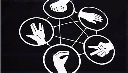
Rock-paper-scissors-spock-lizard game is very popular among teenagers. Our idea comes from a very popular American comedy: Big Bang! In this TV show we always see Sheldon playing this game with his friends. The purpose of this project is to let human play this game with computer’s random variable gestures. There are totally five different gestures included and every gesture can win two of them and lose to the other two. Figure 1 tells us about the basic rule of this game:
In order to achieve our goal, we use the digit camera OV7670 to get human gestures and then use microcontroller to send the image data to Matlab to do image processing, which can reduce the processing time. Finally we resend the results to another microcontroller which can display the game on a TV screen with computer random variable gesture. The hardest part in our project is the data transmission among camera, microcontroller and Matlab because there are some limitations in crystal frequency and Baud rate. Also, the image processing algorithm should be efficient and accurate enough so that we can distinguish the gestures correctly. Last but not least, in the second microcontroller which is used to TV control we cannot use any ISRs because of the TV display. Then the problem we need to solve is to make sure this microcontroller can receive the result signal on time, otherwise there might be some problems which will be discussed later.
High level design
As is introduced above, this game is quite popular among teenagers, especially when they want to make some simple decisions. Actually we were hesitate to doing this project at the very beginning because the camera is hard to debug and we are not sure whether we can get enough speed, let alone we only have 8 MHz crystal frequency because the camera can only work in 3.3 Volts. But we finally decided to do this project just because we want to take challenges and we think about several tricks to speed up the data transmission.
In order to achieve our goal, there are three components required: First is the camera OV7670, this is a digital camera with 3.3V operating voltage. And we need this camera to get real-time human gestures. Then we also need a voltage transfer module on our self-build microcontroller board to get this 3.3 Volts VCC. The last main part in our project is the LCD TV because we need to display both human gesture and computer random gesture on its screen. Additionally, we need a serial port line to communicate with Matlab.
The logical structure in our project is like the diagram below:
There are totally six steps. First: MCU1 tells the camera to capture image; Second: The camera sends what it gets to MCU1; Third: MCU1 sends such data to Matlab to do image processing to distinguish gestures; Fourth: Matlab tells MCU1 the processing result; Fifth: MCU1 sends the result to MCU2 to display; Sixth: MCU2 displays the result on TV and tells MCU1 that it receives the result.
In this project, we have made several tradeoff decisions between hardware and software and all this tradeoff decisions make the whole procedure faster and more efficient.
1) First of all, as the limitation of baud rate and crystal frequency on hardware, if we sent every pixel we got from the camera, the transmission time may be too long. So what we can do was to improve the transmission method on software. We first decided to send one pixel in four pixels, which no doubt could decrease the number of data. Then we did the binarization to every pixel in the microcontroller and combined every eight pixels into one byte to send. In this way we almost increased eight times of the speed. What we did next was to compress the image we wanted to send, which meant we only recorded how many “0”s and how many “1”s according to the order. So if there were successive “0” or “1”, we just needed to send the number of it without sending several times, and this method has been called as run-length coding. These few steps above just helped us to increase the transmission speed to an acceptable one.
2) Then we also did a tradeoff between the total budget and crystal performance. Since the working voltage for the camera is 3.3Vand if we just bought a level shifter chip, it would cost us more budget. So we just bought the LM2596 adj module instead of LM340 which could be added to the microcontroller to let it output 3.3V VCC. But in this way we can only use 8 MHz crystal frequency rather than 16 MHz, which may decrease the baud rate of the microcontroller.
3) Another tradeoff we made is to use INT1 in MCU1 controlled by MCU2 to reset the signal flag when MCU2 received the gesture signal from MCU1. When MCU1 received the gesture information from Matlab, it will set a flag to tell MCU2 which gesture it is. However, because MCU2 was used to control the TV display, it had its own working period and maybe cannot received the signal from MCU1. So what we did was just to let MCU1 wait until MCU2 received the signal, otherwise MCU2 may not be able to receive the signal or receive something wrong.
Standards in use
Four basic standards are used in our design, including camera configuration protocol SCCB, Video Graphics Array protocol VGA, serial communication protocol rs-232, and an analog TV display protocol NTSC.
SCCB is known as serial camera control bus. It is designed by the company OmniVision as a standard to configure the register inside the camera. It is quite similar to the standard IIC protocol, which is described in the webpage below. In detailed design part we will explain the timing issue of SCCB and describe how to implement it software.
http://en.wikipedia.org/wiki/I%C2%B2C
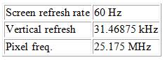
VGA is a widely used graphical standard, it support 640*480 video mode at a refreshing rate of 60 fps. Sequence chart of VGA is shown as below.
In our camera module, horizontal sync signal is named HREF, and vertical Sync signal is named Vsync. PCLK is the pixel clock and so every rising edge of PCLK we can read a pixel from data port. In our camera module, we have 16 bits data port, 8 bit for gray scale data, and 8 bit for hue information.
General timing issues are shown in the table below. To know more about VGA standard, you can visit http://en.wikipedia.org/wiki/Video_Graphics_Array for detailed information.
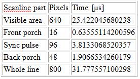
General timing
Horizontal timing (line)
Polarity of horizontal sync pulse is negative.
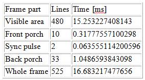
Vertical timing (frame)
Polarity of vertical sync pulse is negative.
The serial port transmission protocol RS-232 has been used several times in lab. So we also reused Bruce’s code for data transmission. You can refer to the webpage below for detail.
http://en.wikipedia.org/wiki/RS-232
NTSC, known as National Television System Committee, is a technical standard for black-and-white television. We use this protocol for writing the user interface on TV. The timing issue of NTSC is difficult and we will talk about it in detail later.
Patents, Copyrights relevant to our project
In our project, we referred to many code offered by Bruce on ECE4760 website. We also referred to webpages and blogs listed below for better understanding the camera chip and image processing code in MATLAB.
http://embeddedprogrammer.blogspot.com/2012/07/hacking-ov7670-camera-module-sccb-cheat.html
http://people.ece.cornell.edu/land/courses/ece4760/FinalProjects/f2012/krs228_dmw255/krs228_dmw255/BlackHack.htmlhttp://www.mathworks.com/help/images/
http://www.getreuer.info/tutorials/matlabimaging
Program/Hardware Design
Hardware Design
Full circuit schematic can be found in Appendix. A.
OV7670 Module
One of the most trick part of our design is to fetch data from CMOS camera. We chose OV7670 as our camera rather than C3088 module used by other students because it’s much cheaper and perform better in resolution. The OV7670/OV7171 CAMERACHIP is a low voltage CMOS image sensor that provide 640*480 VGA output. To successfully get image, several difficulties need to be cleared.
http://www.eleparts.co.kr/data/design/product_file/Board/OV7670_CMOS.pdf
1) Timing issue. Our micro-controller is far slow behind the VGA (QVGA), even if we use 20MHZ crystal oscillation, it’s still challenging to receive a 320*240 video in 30fps.
2) Storage and Transmission issue. Even if we use some weird method to synchronize with the sequence, our Atmaga1284P is likely to run out of memory if we try to storage a frame with 8 bits per pixel.
3) Level shifter issue. The camera fits in 3.3V and 2.5V for low energy consumption. However, our microcontroller prototype board works at 5V so it can’t be connected directly.
Our first touch to solve the third problem is to use a level shifter chip. However it’s too expensive to buy so many level shifter chip (Camera has too many pins). Another choice is only use resistor for tap voltage, but the SCCI interface is duplex, so it will not work. Fortunately, the micro-controller is also able to work under 3.3V, but we have to pay the cost of half the frequency of crystal. Also we may have trouble in communication between to micro-controller, but we find it works well if we put a 330 Ohm resistor between 3.3V and 5V I/O port, because all the I/O port is able to stand 5V and 3.3V is also judged as high in CMOS logic.
To supply 3.3V. We alter the LM340 by LM2596 adj module. LM 2596 adj is designed by TI, Its input can be up to 40V and output is adjustable from 1.2V to 37V. It can offer more than 2A current and it’s cheap. So it’s perfect for our application.
http://www.ti.com.cn/cn/lit/ds/symlink/lm2596.pdf
To solve the problem of different clock domain, the most efficient method is always using a FIFO. In the design, we use AL422b as our FIFO chip. The AL422B consists of 3M-bits of DRAM, and is configured as 393,216 words *8 bit FIFO (first in first out). It’s designed for caching image and its interface perfectly friendly. With FIFO we can store a whole frame of image and read it whenever the camera is free.
http://www.frc.ri.cmu.edu/projects/buzzard/mve/HWSpecs-1/Documentation/AL422B_Data_Sheets.pdf
As we insert FIFO, there is no need to store data in micro-controller. Yet it’s still to slow to transfer picture through USART interface from micro-controller to MATLAB. We tried both FTD chip and MAX233 chip and find the Maxim BAUD Rate is about 38400. So we only transmit a 80*60 image to computer for better speed. In the software part we’ll show more methods to improve the speed.
The wire for the camera, FIFO and micro-controller are shown in the appendix, detailed VGA timing is discussed in high level design standard part. PCLK is used as the written clock of FIFO, written enable is HREF signal (synchronization signal for line) and a control signal from MCU. All other control signals of FIFO comes from MCU. The VSYNC signal (synchronization signal for frame) is sent to MCU INT0 as a reminder.
Video Digital to Analog Converter
The video signal and synchronization pulses are sent to the LCD TV through PORT D.1 and PORT D.0. When generating NTSC video, PORT D.1 and PORT D.0 are used to generate three important video voltage levels. Sync level, equal to 0 volts, which is to control the device; black level, equal to 0.3 volts, which means drawing nothing at this pixel; white level, equal to 1.0 volts, which means this pixel should be white. Those voltage levels can be generated by a voltage divider like below. The video output circuit below is obtained from Cornell ECE 4760 Video generation with AVR page: http://people.ece.cornell.edu/land/courses/ece4760/video/index.html
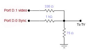
Schematic of Video DAC
Communication Part Description
In our design, we need to do communication and control between both upper computer and MCU1 and also between two MCUs. As an automatic game, the control need to be smooth so that it can keep running without too many interrupts.
The idea of how to communicate between computer and MCU comes from lab4. In lab4, we use PUTTY to set the parameters of PID algorithm, and the micro-controller parses the command and decides what to do. It can distinguish 6 commands, “t” means the MATLAB asks for a new image frame, and the other five commands means that MATLAB has successfully recognized one of the gestures, and then the MCU will notify the other MCU to show the result on TV.
The idea of how to communicate between two MCUs comes from OS class. Because we cannot change any timing in the TV display, it is impossible to use interrupt and timer there. So each time MCU1 want to send a message to MCU2, it needs to lock all the variables until the MCU2 to give a feedback. After the MCU2 run to certain stage and could handle the request from MCU1, it generates an external interrupt of MCU1 to unlock.
Software Design
Full source code can be found in Appendix. C.
OV7670 Module
The Software of camera MCU mainly include 4 part, Camera initialization, FIFO chip initialization, UART transmission and main loop for receiving data form camera module and sending back to MATLAB. The following are the description for each part.
Camera Initialization: this part is written as function in ov7670.c file. To do the initialization, the main task is to configure all the useful registers. To know the meaning of each register, we refer to the user manual book and also several other open source project.
http://hamsterworks.co.nz/mediawiki/index.php/OV7670_camera
http://www.cs.fsu.edu/~baker/devices/lxr/http/source/linux/drivers/media/video/ov7670.c
To configure the register, the first code we need to write is SCCB interface. Generally speaking, SCCB interface is almost the same as IIC interface, SIO_C is the sclk wire and SIO_D is the sda wire, in our system, master device is the MCU and slave device is the camera. Figure below is I captured from datasheet to show the SCCB Timing.
To start, we need to set SIO_C high and make SIO_D from high to low. Then in transmission we capture data at the rising edge of SIO_C. To finish transmission we need to set SIO_C and make SIO_D from low to high.
As we don’t have specific hardware for IIC protocol on our MCU, we decided to use I/O port to simulate this process. Functions are written as InitSCCB, startSCCB, stopSCCB, noACK, SCCBwriteByte and SCCBreadByte. Here we use _delay_us function from <util/delay.h> but it’s reasonable because this part of code is only running at the initialization, so it won’t hold cpu cycles once we began to fetch data.
To understand the SCCI protocol better, you could refer to the functional specification.
http://www.ovt.com/download_document.php?type=document&DID=63
Then we implement function wrOV7670Reg and rdOV7670Reg in OV7670.c to read and write register. As the functional specification mentioned above, the transmission are separated into 3 phases. For write register, the first stage is to write ip_address, which is usually 0x42 for read. The second phase is to write the register address, which is shown in the datasheet. The last step is to write the value of that register. For read register, the first two stage are the same, but we need to restart SCCB and write 0x43 as the ip_address to notify the camera that we want to read register, then we call SCCBreadByte to get the exact value for a register.
The last function we implement is OV7670_init. In this function we use a loop to do register configuration and read several to check if it’s working. We can also configure the window size of the camera in this function, the default value is 640*480 pixels per frame.
FIFO chip initialization:
To initial FIFO chip, we need to make all the read and write pointer clear. The only tricky part here is all these signals are active low, so we need to clear and then set.
UART transmission:
We use the UART code on the course website offered by BRUCE. With one stop bit, the highest BUAD Rate is 38400.this is far from enough for transmitting a photo with 640*480 pixels in real time. So we use bit concatenate and run-length coding to improve the transmission time.
Main File:
The main file is composed with an external interrupt and while (1) loop.
The external interrupt detect rising edge of VSYNC signal, each time the VSYNC count plus 1in the interrupt, it is cleared in the main loop when MATLAB is requiring for data. When VSYNC_cnt is equal to 1, we do the FIFO initialization and activate the FIFO enable signal, so a total frame will be loaded into FIFO automatically. When VSYNC_cnt equals to 2, we clear the FIFO enable signal and set FIFO data ready signal to 1, so the main loop knows that data is ready and can fetch at any time. This is like a request-ready handshake protocol and it works well.
In the main loop, the first thing to do is to check the command code. Once it receives the command to transmit data, it clears VSYNC_cnt and wait for FIFO data ready signal. Considered the space limited, we don’t store any data in the MCU, each time it received a data, the data is sent to computer through serial port. We used this method to receive a picture with 1*640*480 byte and show it on MATLAB, but it takes more than a minute to finish transmission. In the high level design part we have discussed the detail about how to compress the image.
Image Processing in Matlab
In order to solve more time, we decide to use Matlab in PC to do the image processing. At the very beginning of image processing, we need to extract the image information comes from the MCU1 because the data from MCU1 only tells you the arrangement of logical 1 and 0. So Matlab need to transfer every byte data into bits for every bit means one pixel, and then we reshape this image to an appropriate shape and get rid of the noise from camera edges.
What we actually do next is to judge what gesture it is. It is hard to do any judgment if every image has a different angle, so we first using Hough Transform Algorithm to rotate the image until all the fingers except the thumb point to left or right in the image. Then we distinguish every gesture in the following order:
1) Every gesture pixel is equal to 1 and every background is equal to 0. So what we do first is to determine how many 1 to 0 and 0 to 1 changes when we do the column scanning in the image. Here Paper has the maximum changes of 8 and Rock has the minimum changes of 2. So now we distinguish two of them.
2) Among spock, scissors and Lizard, we notice they all have four changes between gesture and background, but when you calculate the differences between two fingers’ slopes in one gesture, you will also notice that the slope difference in Lizard is always contrast to the others. So doing slope calculation we distinguish gesture Lizard.
3) The most difficult part is to distinguish Spock and Scissors for they have all the same parameters above. But we then notice that in gesture Spock the thumb increase the maximum width of the gesture while the width through mass center stay nearly the same. So we use the ratio between maximum width and mass center width to distinguish these two gestures, but the accuracy may not be as perfect as the three above.
Here one thing need to be mentioned is that because we do not know the total size of the gesture in one image, so we can never set a threshold value to determine any width or length. What we can use is just the ratio in your gesture and that’s why we didn’t use the threshold value to judge Spock and Scissors because it may change every time you capture the image.
Finally we print out the result and send back to MCU1 and then waiting for the next image information. Actually Matlab is not good at doing “while(1)” loop, so the function may break down after processing about 100 images and you need to run Matlab again in order to continue the game.
Video Generation
Televisions are raster-scan devices. They move a single electron beam across the display tube line by line to draw the image. The process is like that the beam starts in the left corner of the first line, then scan quickly across to the right corner drawing the first horizontal line of the image. After it finished the first line, the beam goes back to the left and drawing the second horizontal line. This process continues until all the lines in TV frame have been painted. A complete TV image has 525 lines and is fully painted 30 times per second. When displaying, each full image is split into two frames of about 262 lines each, where the first frame contains lines 1, 3, 5, 7…, and the second frame contains lines 2, 4, 6, 8…, and each frame is displayed at a rate of 60Hz. It takes 63.5us to draw a line. When drawing each line, the video signal uses a changing voltage to indicate the intensity of pixels. Below is a depiction of NTSC signal behavior drawing four lines of video (reference from Stanford EE 281, Laboratory Assignment #4 "TV Paint"). Each line starts with a horizontal sync pulse which tells the TV to begin a new line. After the sync, video signal is a varying voltage between 0.3V and 1V, which controls the intensity of pixels.
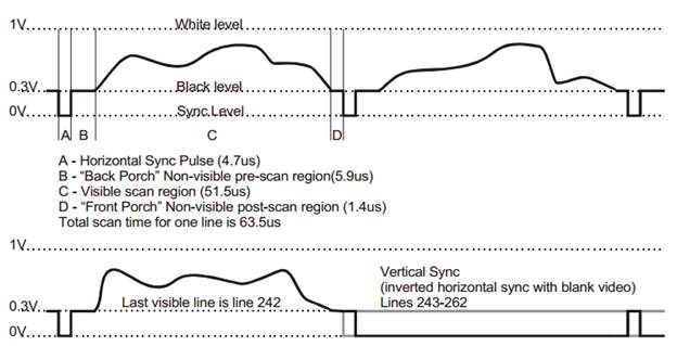
NTSC signal behavior of four lines. [Stanford EE 281, Laboratory Assignment #4 "TV Paint".]
Code for video generation is modified from the Cornell ECE 4760 Video generation with AVR webpage: http://people.ece.cornell.edu/land/courses/ece4760/video/index.html, where the resolution is 160 horizontal x 200 vertical. The code uses USART as a pixel shift register and sets the USART into SPI master mode. The horizontal and vertical sync are generated by Timer1 Compare-match A ISR to make each frame exactly 1/60 sec to conform to the NTSC standards. The Timer1 Compare-match B ISR puts the MCU to sleep just before the match A ISR goes off, so that entry into the match A ISR is cycle-accurate. Two big tables in flash memory, prog_char smallbitmap[39][5] and prog_char ascii[128][7], contain the bitmaps for the large and small characters, which are used to show the game information by calling the function video_puts(char x, char y, char *str). Five big tables, prog_char paper[], prog_char rock[], prog_char sci[], prog_char liz[], prog_char spock[], which are generated via processing five graph in Matlab, are used to display five gestures, including paper, rock, scissors, lizard and spock, on TV by calling the function video_pt(char x, char y, char c).
Game State Machine
When the game begins, the characters ‘YOU’ and ‘TV’ display at the top of the TV screen, indicating two players of the game. Meanwhile, five gestures, paper, rock, scissors, lizard and spock, appear on the right part of the screen in a scrolling way, representing player ‘TV’. We use the variable ‘state’ to control the appearance of five gestures in the while loop. When the MCU, controlling the TV display, receive the information about human gesture from the other MCU through PORT A, it will let TV show the human gesture on the left part of the screen. At the same time, the player ‘TV’ stops scrolling. Based on the gestures of human and TV, MCU can figure out which one wins and display the result on the bottom of the screen.
Results of the Design
In our project, we have solved two main problems: data transmission speed and gesture identification. Data transmission contains the transmission between camera and microcontroller, microcontroller and Matlab, microcontroller and microcontroller, microcontroller and TV. Since the frequency in camera is very high and the frequency in microcontroller is much lower, we use a FIFO between them so that the capture data can be stored in it and then send to microcontroller, the speed will be determined by the microcontroller. The transmission between two microcontrollers is simple but we added INT1 in MCU1 controlled by MCU2 so that MCU2 can receive information more efficiently, otherwise it may wait for more working periods. TV has its own working timeline so that we cannot change it. What we care most is the transmission between microcontroller and Matlab, and after the tradeoff we talked in high level design part, we decrease the transmission time remarkably so that it can reach our basic requirement.
For accuracy we just develop the algorithm which is discussed in the software design part. Through this algorithm, we cannot say we can get 100% correct but if we can get the full image of the gesture, the accuracy is shown in the table below through 50 tests.
Our project is quite secure and clean and everybody can play with it. What you need to do is just put your hand over the camera so that it can capture your gesture and show the game result on the TV screen.
For usability, we strong encourage everybody to play the game with some special needs. First of all, you should put your gesture to an appropriate height and position so that the camera can capture your whole gesture, otherwise it will lead to some false results. Second is that you need to make your gesture as standard as possible so that the judgment can be highly accurate.
Conclusions
2) Also, we learned the TV time sequence and how to display the pattern we want on the TV screen.
3) Through this project, we also know how to do some image processing. Even though the image processing is done in Matlab, but we also have confidence to do it on microcontroller if speed permits.
Generally speaking, the final results of our project exceeded expectations. As we have already discussed before, the transmission time once might be quite long and we may not play this game smoothly. However, several transmission tricks we made to reduce the time so that we can play a nearly real time game. Everybody can play with our game as long as the gesture can be fully captured by the camera.
For next time, I think what we will do is to improve the algorithm so that it can distinguish your gesture even though the camera does not capture the whole hand. Additionally, if permitted, we decide to use other MCU which can run faster and work correctly under high baud rate. With such MCU we may do the image processing on microcontroller and we can display the gesture on TV more quickly.
Ethical considerations:
We promise all of our experiments are safety, wealthy and disclose promptly factors which may endanger the public and environment. All the data we used are realistic and exactly what we got from experiences and all the methods and estimates we claimed are realistic and we definitely used them in our project without cheating. Of course in our project we did not bribery anyone in order to get illegal help. However, we are very appreciated to the help from those who have helped us. Especially we want to thank Bruce Land, the director of this course and Tian, Gao and Cameron Glass, the TA of the this course. In our project we once had the problems we cannot solve appropriately, but Bruce, Tian and Cameron gave us some suggestions which really help a lot.
Frankly speaking, we are eager to help others and we are friendly to share the experiences we got related to some problems and treat fairly all person no matter the differences in race, religion, gender, age or national origin. Actually we have a very nice group with very happy working atmosphere and everybody is patient and eager enough to help each other to solve each one’s technical problems in the whole project.
Appendix
A. Schematic
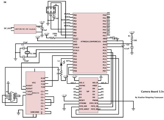
Schematic of Ov7670 module
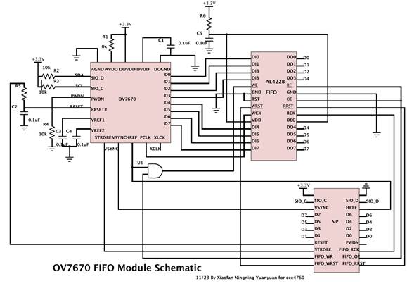
Schematic of OV7670 FIFO Module
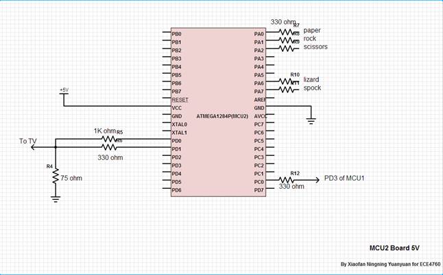
Schematic of connection of TV and MCU1
B. Parts List and Cost
All the modules possibly need are shown in the table below.
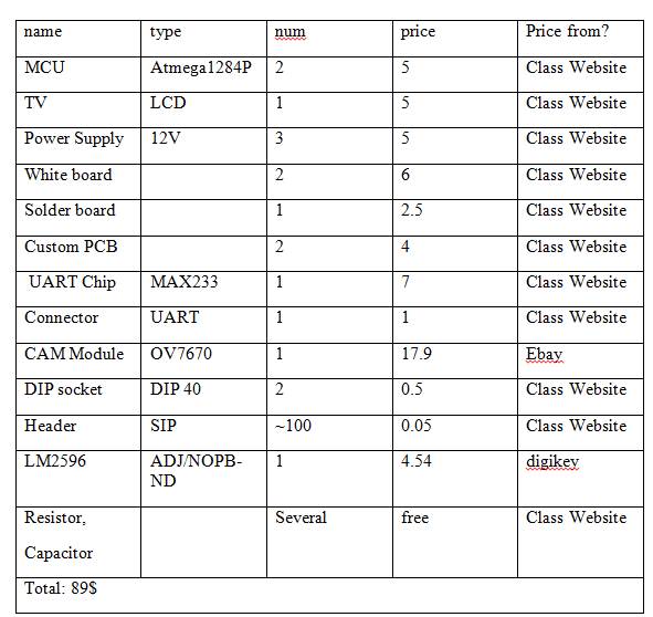
Table 1 Budget list
Camera module
http://www.ebay.com/itm/221200996848?ssPageName=STRK:MEWAX:IT&_trksid=p3984.m1423.l2649#ht_3452wt_1105
digikey
http://www.digikey.com/product-detail/en/LM2596T-ADJ%2FNOPB/LM2596T-ADJ%2FNOPB-ND/363709
Generally speaking, our budget is a little out of expectation, for TV and camera are all cycle consuming so we are forced to use two MCUs. The result is that we almost double the budget for using two white boards, three power supplies and two customer PCB board. To save budget we get rid of all flat cables which may cost 1 dollar each, and solder the camera module on a solder board, which takes great effort but saves us almost 20 dollars. Another way to save budget is to make a power supply module so we can use only one adapter. We didn’t do that because the budget is enough.
C. Code
Camera Module
TV Module
Image Processing Module
D. Labor division
Soldering |
Xiaofan Luan & Ningning Ding |
|
Hardware |
TV module |
Yuanyuan Gong |
Camera Module |
Xiaofan Luan & Ningning Ding |
|
software |
TV module |
Ningning Ding & Yuanyuan Gong |
Camera module |
Xiaofan Luan |
|
Matlab module |
Xiaofan Luan & Ningning Ding |
|
Serial communication |
Xiaofan Luan & Ningning Ding |
|
Hardware testing |
All of us |
|
Software testing |
All of us |
|
Reference
I2C Protocol
http://en.wikipedia.org/wiki/I%C2%B2C
VGA protocol
http://en.wikipedia.org/wiki/Video_Graphics_Array
RS232 protocol
http://en.wikipedia.org/wiki/RS-232
Knowledge of pixel format and signal
http://embeddedprogrammer.blogspot.com/2012/07/hacking-ov7670-camera-module-sccb-cheat.html
OV7670 driver code in verilog
http://hamsterworks.co.nz/mediawiki/index.php/OV7670_camera
OV7670 reference configuration on LINUX
http://www.cs.fsu.edu/~baker/devices/lxr/http/source/linux/drivers/media/video/ov7670.c
Our idea comes from
http://people.ece.cornell.edu/land/courses/ece4760/FinalProjects/f2012/krs228_dmw255/krs228_dmw255/BlackHack.html
Image process toolbox of Math works
http://www.mathworks.com/help/images/
Brief introduction of Matlab image processing
http://www.getreuer.info/tutorials/matlabimaging
OV7670 Datashett
http://www.eleparts.co.kr/data/design/product_file/Board/OV7670_CMOS.pdf
LM2496 datasheet
http://www.ti.com.cn/cn/lit/ds/symlink/lm2596.pdf
Al422B FIFO data sheet
http://www.frc.ri.cmu.edu/projects/buzzard/mve/HWSpecs-1/Documentation/AL422B_Data_Sheets.pdf
SCCB bus description by omnivision
http://www.ovt.com/download_document.php?type=document&DID=63
TV time sequence from standford
http://www.stanford.edu/class/ee281/handouts/lab4.pdf
TV display help from former 4760 lab
http://people.ece.cornell.edu/land/courses/ece4760/video/index.html
Vender of OV7670 module
http://www.ebay.com/itm/221200996848?ssPageName=STRK:MEWAX:IT&_trksid=p3984.m1423.l2649#ht_3452wt_1105
Vender of LM2596 module
http://www.digikey.com/product-detail/en/LM2596T-ADJ%2FNOPB/LM2596T-ADJ%2FNOPB-ND/363709
Acknowledgements
We would like to sincerely thank Professor Bruce Land for his guidance, help and support throughout whole semester. His detailed lectures and insightful labs gave us a solid foundation that allowed us to tackle this final project idea. We would also like to appreciate all of the ECE 4760 TAs, especially Cameron Glass and Tian Gao