Introduction

In the modern American classic, Rocky IV, Ivan Drago (portrayed by Dolph Lundgren) is shown utilizing a then-futuristic electronic punch meter (in addition to anabolic steroids) in his quest to triumph over Rocky in one of the Cold War’s only face to face confrontations. While we dispensed with the communist symbolism (and controlled substances) in our final project, we aim to create a boxing trainer that teaches various basic and advanced rhythms and combinations while also providing the user with a gauge of timing and accuracy. While we desired to have “built-in” sequences to train the user, we also desired to allow the user to self-program and store their own practice combination sequences. We attempted to do this without exceeding a budget of $100.


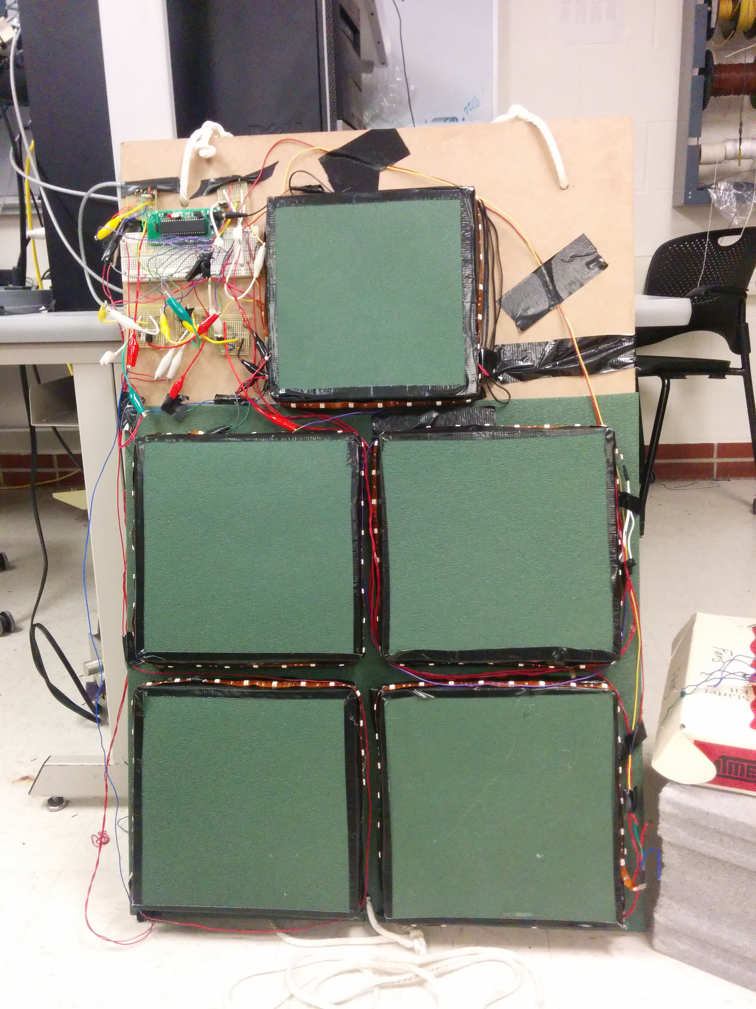
It’s probably easiest to get a sense of the subsystems that make up our project by considering it in action. Our system consists of five force sensing pads arranged in the profile of a human torso, as seen to the right. Each pad is surrounded by a bright LED ribbon. The user punches these pads to practice their combinations- the combination rhythm being indicated by the flashing of the LED ribbons. If the user fails to strike the pad within a set deadline, the next punch in the sequence proceeds. Our video provides both an overview of the project as well as a brief demonstration.


The feedback to the user (in terms of reaction times, accuracy, and related statistics) as well as the programming interface is by serial communication. We typically interface with a PC using a USB-RS232 cable and PUTTY. Since PUTTY is compatible with virtually all modern computer systems, this allows pretty much anyone to use our system with a laptop (or a dummy terminal).


Throughout this project, we followed a modular design approach. We started out with a few discreet LEDs and pushbuttons soldered to a broken-in-half solder board and in the first two weeks implemented code to simulate a game similar to “Simon” (link). We then tackled the force sensor issue, eventually coming to a sufficient solution that could be easily and accurately be reproduced using a few jigs. The performance of these sensors led us to develop a simple passive analog signal conditioning circuit which was paired with each sensor. After ordering power MOSFETS and the LED ribbons towards the conclusion we integrated our final lightning control and signal conditioning circuits onto (fractional) solder boards that were paired individually with each of the five force sensors. After a seemingly unending period of wiring, checking wiring, hardware debugging, software debugging, reprogramming, significantly heightened systolic blood pressures, caffeine overdoses, and sleeplessness we delivered our demo successfully.

Design Overview

Insofar as software was concerned the code on the microprocessor was used to control the timing of punch routines, run the “menu” and combination programming functionality over serial communication. It also interfaced with the force sensors using its analog to digital conversion capability.


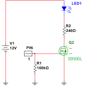
The LED ribbons run on about 3 amperes of current at 12V, which meant that we had to drive them indirectly using a switching power MOSFET circuit.


We had originally intended to provide users with accurate measurements of their punch peak forces using manufactured load cell and/or planar force sensor products integrated into the pad itself. Unfortunately this proved to be an expensive problem to solve, given the magnitudes of forces we estimated to be experienced by the components. Alternative DIY solutions were found online. We originally attempted to build some of the sensors used in the Cassius Punching Bag . These sensors relied on electrostatic discharge (ESD) foam, like the kind common integrated circuits are shipped on, and were designed for our same measurement application. Unfortunately, given the inexpensive surplus foam we had available, we were not able to achieve “macroscopic” sensor results. For this reason, we ended up making pads of our own that relied on variation of ESD foam resistance with the surface area of metal contact.

These sensors weren’t exactly industry grade themselves, and after some trial and error we developed a passive filter circuit that allowed us to measure a clean, consistent punch signal on a microprocessor ADC line. Furthermore, our conditioned signals exhibited behavior in the spirit of Drago’s device- increasing in magnitude (qualitatively) with the increase in punch impact.

As for the actual realization of a jumble of wires and square pads into something one could actually practice boxing with, we relied on our varied life experiences, as well as the experiences of salespeople at Lowe’s, Home Depot, and Ace Hardware to come up with a way to (safely ) mount our product on a metal exterior door.

As far as prior art was concerned, products similar to this one are on the market, the most similar one we found being the Nexersys Pro Unit LINK. This unit is clearly aimed at a bit different market (costing about $7000) and provides feedback information far beyond our scope (such as 3 axis force information) and features an onboard monitor. It is also different mechanically, being much larger and with “punch pads” that move when struck. It appears to have a game setting similar to our main project goal, but signals which pad to hit on its onboard monitor.

Force Sensor and Circuitry

After determining that the force sensors available in lab (which were designed for human machine interfaces on appliances such as microwaves) were unsuitable for our application given the forces we intended to apply over the areas we intended to apply them, we began to do some online research. Over budget concerns, we initially went for the design suggested in the Cassius Project. The author of that project claimed to have been able to make application appropriate force sensors by layering ESD foam in between two chicken wire sheets. The chicken wire was covered with cardboard, and the whole thing was taped up. The author does make mention that some ESD foams seem to work better than others and implies that several brands were tested. No results are stated, however, and given the prices we were finding for ESD foam online and time constraints we felt that the surplus lab foam (for which we were charged $1) was our best option. This foam was not observed to have a resistance that changed noticeably when compressed. It was, however, observed to have a measured resistance that varied greatly with the surface area of metal contacts applied to measure it, decreasing with increasing contact area, as expected. This property led to our parallel development of our own force sensor.


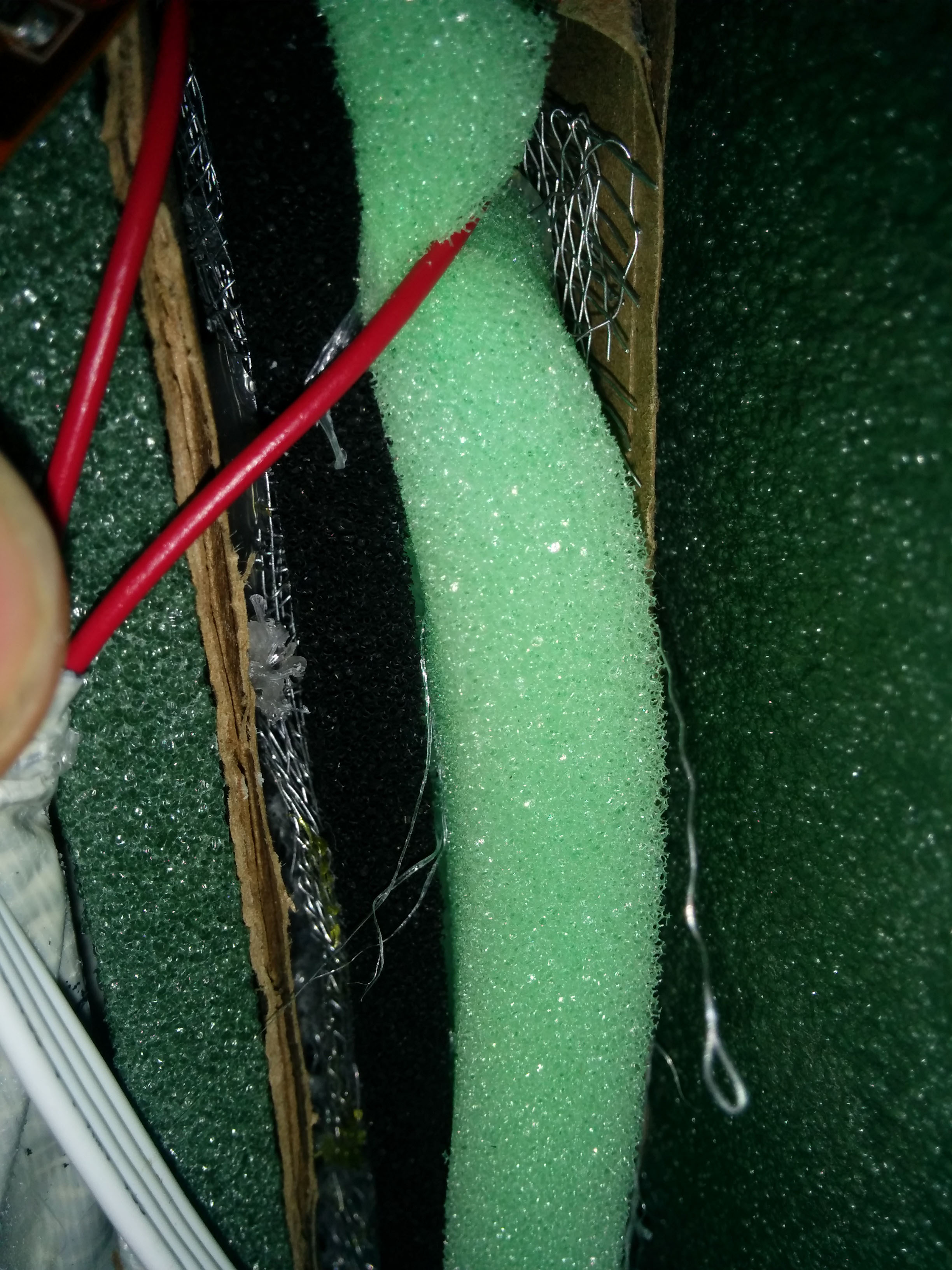
Our sensor consisted of two square pieces of fine aluminum window screen with foam structures places in between them. One of the foam pieces was made from the conducting ESD foam and was simply a square, while the other was a piece of half inch thick insulating foam rubber with quarter inch slits cut approximately half an inch apart, for approximately 12 slits per sensor. In each of the screen pieces, we thread (copper) wire through the (aluminum) screen’s holes in a “Z” pattern and bond the metals together with conducting glue. The jailbar foam is then hot-glued to the ESD foam, and then the composite foam is sandwiched via hot glue between two of the wire-threaded screens. The screens are then covered on their exposed sides with cardboard that has been rolled with a wine bottle to reduce its brittleness (by popping any trapped air pockets). We used four 10” by 10” sensors to create the “body” of a figure, and a 9” by 9” sensor for the head.


We made our sensors very carefully, and ensured that they were as similar as possible. While in testing we did find that harder punches lead to more screen contact to the ESD foam (and hence a lower resistance measurement) we did not find this measurement to be linear, and found them to be easily conflated with the size of the object doing the punching (as would be imagined). As such, we dispensed with the idea of using the sensor data as a true unit of punch intensity. However, for a given user, the relative resistance values obtained when striking the pad have a negative correlation with the force of the punch. However, between different users it is hard to quantify the level of correlation, and as such, we were back in the territory of Ivan Drago, displaying (smaller) unitless numbers on a display.


A schematic of our final circuit is shown. The sensors actual data was read by placing it in voltage divider with a 1M resistor and measuring the voltage drop on the latter with the ADC. The controller is set to use a 5V analog reference voltage. We did lots of measurements on the oscilloscope to examine the shape of the raw received signal, and found it to be plagued by “bouncing” and high frequency noise similar to that found with a pushbutton switch. Examining these signals and considering the time scale of a human punch, we settled on low pass filtering the signal with a filter with a time constant of about 100ms (we measured the timescale of a human punch to be on the order of 10ms). We still found that even with this filter negative voltage swings (which occur for a reason we still cannot wrap our heads around) could reverse the polarity of the charge stored on the capacitor. In the true spirit of engineering, we placed a diode in parallel with the capacitor that (normally in reverse bias) effectively removed the negative voltage swing at the expense of a bit of reverse leakage current. We implemented our low pass filter as a combination of a (quite large) 1MΩ resistor in series with a 100 nF capacitor, so this reverse leakage did noticeable reduce the voltage at the filters’ outputs. This parasitic voltage drop across the 1MΩ resistors effectively reduces the dynamic range of our measurement from very close to the entire 5 volts to about 3.5 volts. Using a larger capacitor and smaller resistor in future iterations would certainly be to our benefit. It is also notable that the reverse biased diode increases the capacitance of the filter circuit. However, even with our chosen implementation the measured peak force signal still scales well with the increased force of a punch and unambiguously allows us to make a quantitative decision (in software) whether or not a punch has occurred based on thresholds determined from measurements.


Lighting and Construction

As stated, we could not drive the LED ribbons directly from the MCU due to the fact that they source a large current. We found a power supply that was sold with the LED ribbons that could run both them and our processor (on the custom ECE 4760 breakout board) simultaneously. This allowed us to have two rail voltages, Vcc (at 5V) from the controller and a 12V rail with a common ground. We chose the Fairchild Semiconductor fqp30N06L to gate the LEDs using digital outputs from PORTB on the controller. Setting the gate of the MOSFET to high inverts the MOS channel and turns the LEDS on.

Mechanical

We used medium density fiberboard covered with a glued-on layer of surplus US Army Sleeping mat as a backing for our sensors. We additionally covered the cardboard faces exposed by the cardboard with pieces of the army mat. We tapped two holes into the top of the fiberboard equally spaced from the center, and centered at the base of the board. We had some nautical line, joyce hangers, and a cinderblock lying around and managed to attach our system to a metal door of a maintenance closet in Philips hall. We attached some surplus foam to the back of the board to cut the noise.

Software Design

The code for this program can be divided into three distinct section: initialization, user input via PuTTY (or other serial terminal), and gameplay.

Initialization

Our program first defines both the hardcoded programs and empty arrays to hold user-inputted training regimes. Additionally, arrays are initialized to hold the training results. Following this, the ADC is configured to use the 5V reference voltage, and the ADC clock is set to a prescalar of 64 to maximize accuracy of readings given the time insensitivity of our project. Only the top 8 bits are used, in order to ease storage constraints upon gameplay.

Timer0’s overflow ISR is also initialized to increment various timing variables for both reaction time, timing constraints, and “global” program time. Timer0 is then set to a prescalar of 1, and its overflow interrupt is enable, along with all other interrupts. At this point, the program moves on to its serial interface.

User Input

The stdout and stdin of the program are both defined to be the same UART location, in our case the UART pins, which are connected to a UART to USB cable, which spoofs a serial COM port for the computer. The user can then send and receive messages with any properly configured serial terminal.

The program first welcomes the user and then prompts them to select their training regimen. Currently, three different hardcoded programs of variable difficulty are featured, as well as a self-programmed option. All of these programs consist of a series of punches with “release” and “deadline” time defined relative to the previous timing constraint. This methodology prevents the user from inputting an “impossible” combination.

Once the user is finished inputting their combination, which can be up to 100 punches (a challenging round for most amateur boxers), the program prompts to see if the user would like to store their program into EEPROM. Given the limited size of EEPROM, a user can only save one program at a time. Once the program is finalized, the head of the arrays for punch location, release time, and deadline time are all stored to be iterated additionally. Additionally, the number of punches is stored as the loop iterator. As a quick confirmation, the entire training regimen, with timings is printed to the user prior to starting.

Gameplay

The gameplay occurs primarily within a single for loop which iterates through each punch, and its respective parameters. First, the virtual timer used for timing constraints is set to 0, and the program waits until the time has passed the defined release time before continuing to the next section. Each force sensing pad is wired to a distinct analog-digital converter line. . For a given punch, we consider only the ADC channel corresponding to the force pad to be punched- that is, striking any other (non-prompted) pad will not cause any effect. The position of the punch to be thrown by the user is loaded by the program, and used to define both the current ADC channel, via ADMUX, and to light the corresponding LED strip, via a MOSFET gated by a PORTB pin

At this point, the code enters a do-while loop where the selected ADC channel is constantly polled. The ending conditions of the loop are if either a punch is detected or if the deadline time expires. Within the do section, as soon as the ADC passes a predefined value, in our case 25/255 was used because it was found to be large enough that ADC noise never accidentally triggered the device while still low enough that a light jab can still register as a hit. Following this, the peak value of the ADC is determined by constantly saving max(previous max, current reading). We introduced a bit of hysteresis into the system and do not consider the punch to be completed until the ADC value falls below 20/255. This prevents small fluctuations about the threshold from prematurely ending the punch before its true maximum voltage is detected. At this point, the program will print out a line for each punch. For a hit, it will give the user reaction time, global time, and the reading of the ADC, comically labeled “SPI” for Soviet Punching Index. For a miss, the user will be informed of the hit window timeframe, as well as the global time at the conclusion of the miss.

Finally, some statistics are returned to the user in order to improve their future boxing experiences. The program calculates the user’s accuracy for each pad, as well as the average reaction time for each pad. The information is displayed as quantities within an ASCII diagram of the device sensors. Following the report printing, the user is asked if they wish to play again, at which point the game restarts from the beginning.

While the overall software design is not extremely hard to comprehend, the method allows for easy extensibility. First, because all menus are constructed with serial print statements, all it takes is an “if” statement for a new menu. Additionally, given the easy of altering the user interface, additional programs can be easily added for more tailored training. Plus, punch programs are parameterized perfectly to prevent painful programming.

Moving forward, possible improvements include introducing more advanced reporting systems. Possibilities include correlating pads with reaction time and “force”. This would provide a more thorough view of a user’s strong and weak offensive zones. A possible format would be to graph force against reaction time for all of the pads to allow a user to further granulize their boxing prowess. More aggressive software improvements include finding ways to distinguish between various punches’ “signal” given that a hook and a jab have very different contact profiles.
Results

Overall, our can accurately and quickly prompt a user to strike a panel. It successfully times the user's reaction, and can glean some information about the force of the user's punch. However, the current force measurements are not purely linear with actual force, and calibration and testing needs to be done via dropping weights.

From a safety perspective, there are many challenges due to the physical nature of the device. First, the user must make sure to wear proper protective gear, including but not limited to hand wraps and gloves. Additionally, the user should be physically fit, and preferably knows the basics behind punching something. From a accessibility standpoint, some users may struggle with the device due to the fixed height as well as lack of a variant for users without arms.

Conclusions

We were able to accomplish most of the goals we set out to with this lab. Insofar as future changes, it would be interesting to obtain a better calibrated force reading from the pads. Furthermore, there are many interesting things we could do with regards to pre-generated programming, for instance, we could easily create a random punch sequence and set timing levels for varying difficulties. Furthermore, we could support punching multiple pads at once.


We do not see prior art as an issue with this design. We did, however, abide by the IEEE code of ethics. We state the principals, from www.ieee.org , below:

“We, the members of the IEEE, in recognition of the importance of our technologies in affecting the quality of life throughout the world, and in accepting a personal obligation to our profession, its members and the communities we serve, do hereby commit ourselves to the highest ethical and professional conduct and agree:


  1. 1. to accept responsibility in making decisions consistent with the safety, health, and welfare of the public, and to disclose promptly factors that might endanger the public or the environment;
  2. 2. to avoid real or perceived conflicts of interest whenever possible, and to disclose them to affected parties when they do exist;
  3. 3. to be honest and realistic in stating claims or estimates based on available data;
  4. 4. to reject bribery in all its forms;
  5. 5. to improve the understanding of technology; its appropriate application, and potential consequences;
  6. 6. to maintain and improve our technical competence and to undertake technological tasks for others only if qualified by training or experience, or after full disclosure of pertinent limitations;
  7. 7. to seek, accept, and offer honest criticism of technical work, to acknowledge and correct errors, and to credit properly the contributions of others;
  8. 8. to treat fairly all persons and to not engage in acts of discrimination based on race, religion, gender, disability, age, national origin, sexual orientation, gender identity, or gender expression;
  9. 9. to avoid injuring others, their property, reputation, or employment by false or malicious action;
  10. 10. to assist colleagues and co-workers in their professional development and to support them in following this code of ethics

“With regards to the first principal, we state herein that our product should be used only by adults who have been deemed healthy enough to exercise by their physician. We will not offer it for sale until it we have established guidelines for use of our product with protective equipment (such as boxing gloves) in consultation with exercise safety and medical professionals. We will also provide guidelines for safe installation of our product that account for secondary and unintentional use cases.

As for the third principal we will be especially clear in any marketing the practical limits associated with our equipment, including, but not limited to, resolution of reaction time. We will also be clear about how our force measurements ought to be interpreted (with a grain of salt, and in relative terms for one user with no correlation to measurement units). For principal number five, as students of electrical engineering we are willing to contribute to the education of others by providing schematics and plans for this project, as well as by clearly delineating all potential risks to potential owners of this product.

As for the sixth and seventh principals, we vow to not sell this product until it is truly a complete product and has been evaluated by third parties for safety and accuracy. Furthermore, we will conduct a full investigation into any prior art that exists and may affect this products status as intellectual property.

Certainly as human beings we will seek to always adhere to the second, fourth, eighth ,ninth, and tenth principals, although they weren’t especially relevant to this product.

Budget, all values in cents for large numbers

  • Foam Rubber
    Joann Fabrics
    890
  • Conductive Glue
    RadioShack
    1098
  • Metal Screen
    Home Depot
    1000
  • Army Pad
    Ebay
    650
  • MDF Backing
    Home Depot
    775
  • ESD Foam
    Cornell
    100
  • Protoboard
    Cornell
    600
  • Solder Board
    Cornell
    250
  • ATmega1284P
    Cornell500
  • FQP30N060
    DigiKey
    524
  • Circuit Board
    Cornell
    400
  • DIP Socket
    Cornell
    50
  • LED/Power Supply
    Amazon
    2150
  • Liquid Nails
    Home Depot
    249
  • Cardboard
    Home Depot
    174
  • Total


    9522


References and Acknowledgements


Special thanks to Dr. Bruce Land, as well as to all of the TAs and consultants for ECE4760 for their support and assistance.


ATMega 1284P Data Sheet


Code Listing