Nick Teo (gt224@cornell.edu)
Roshun Alur (ra469@cornell.edu)
Ian Vermeulen (iyv2@cornell.edu)
Overview
A modular electronic drum kit that allows recorded samples to be used as drum sounds. We decided to build a modular electronic drum kit because we thought it would be an interesting project to be able to record ourselves and use our own voices or sounds as drum noises.
High Level Design
Rationale and Project Inspiration
Out first idea for the project was a concussion helmet that would use a number of force sensors and some accelerometers. After some time working on that project, we decided that we didn’t want to continue and instead chose to create the DRUM SET. All of us in our group enjoy listening to and creating music, so we thought it would be a good use of the
force sensors that we had already sampled. We looked through other projects that had been done before that would be similar to ours and found that it was a feasible final project.
Logical Structure
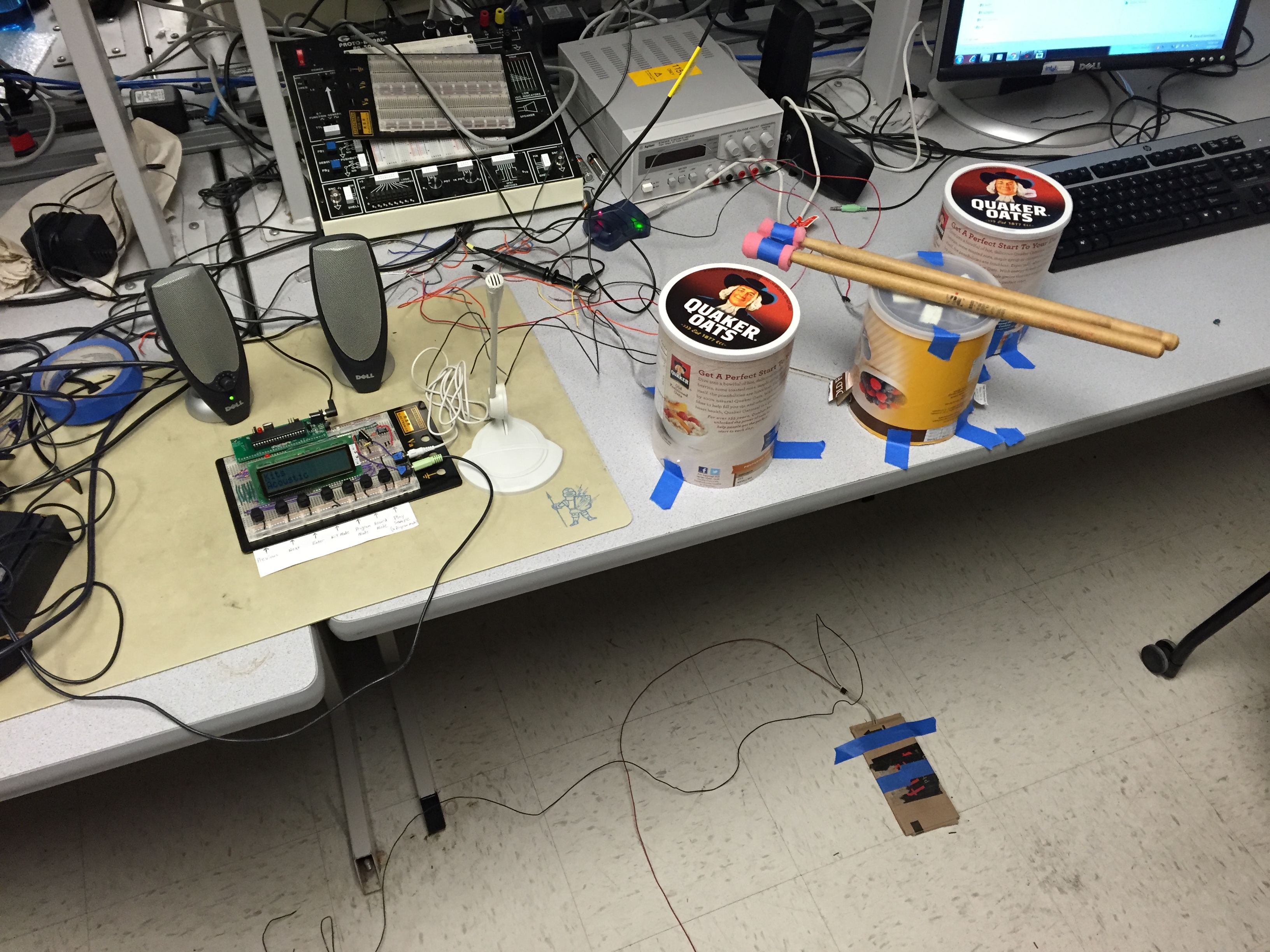
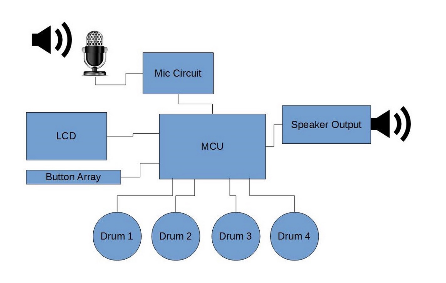
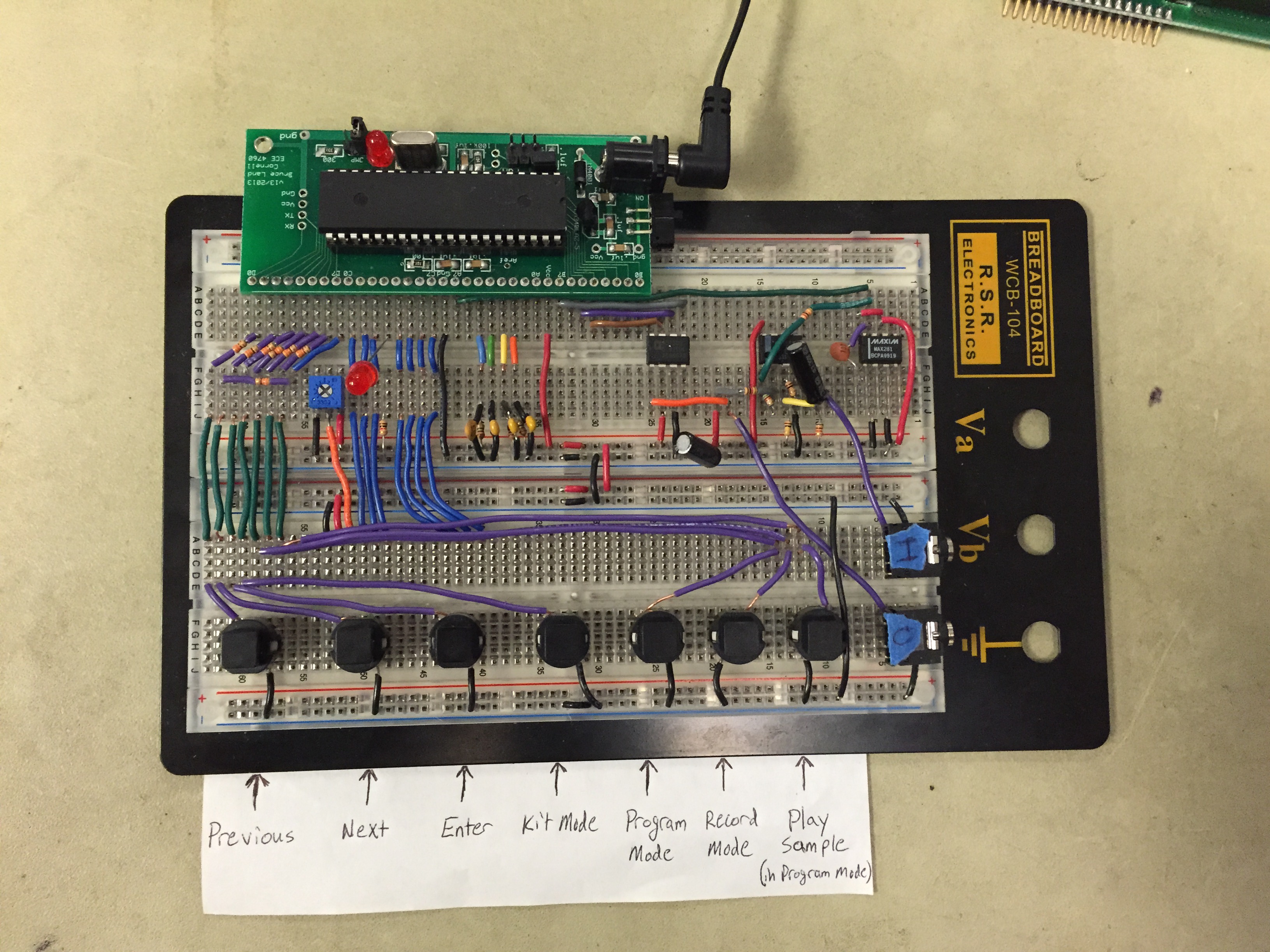
This project involves four major components: the user interface (controlled via 7 pushbuttons and a 32-character LCD display), the drums (connected to the ADC ports of the microcontroller), a microphone circuit with an amplifier and low-pass filter (also connected to an ADC port), and the speaker output that is produced from a DAC.
Hardware/Software Tradeoffs
This project involves four major components: the user interface (controlled via 7 pushbuttons and a 32-character LCD display), the drums (connected to the ADC ports of the microcontroller), a microphone circuit with an amplifier and low-pass filter (also connected to an ADC port), and the speaker output that is produced from a DAC.
Standards
We used the Serial Peripheral Interface standard in our project to interface between the MCU and the AD7303 DAC.
Borrowed Code
The code was used to create the 22kHz sampled files was taken from the Step Sequencer Drum Machine project. The code downsamples the samples to 22kHz and converts them into char arrays in a header file. We slightly modified the script to better fit our other code and limit the sample length. We used our own wav files to create the samples for our project.
Subsystems
Force Sensors and Drums
Hardware
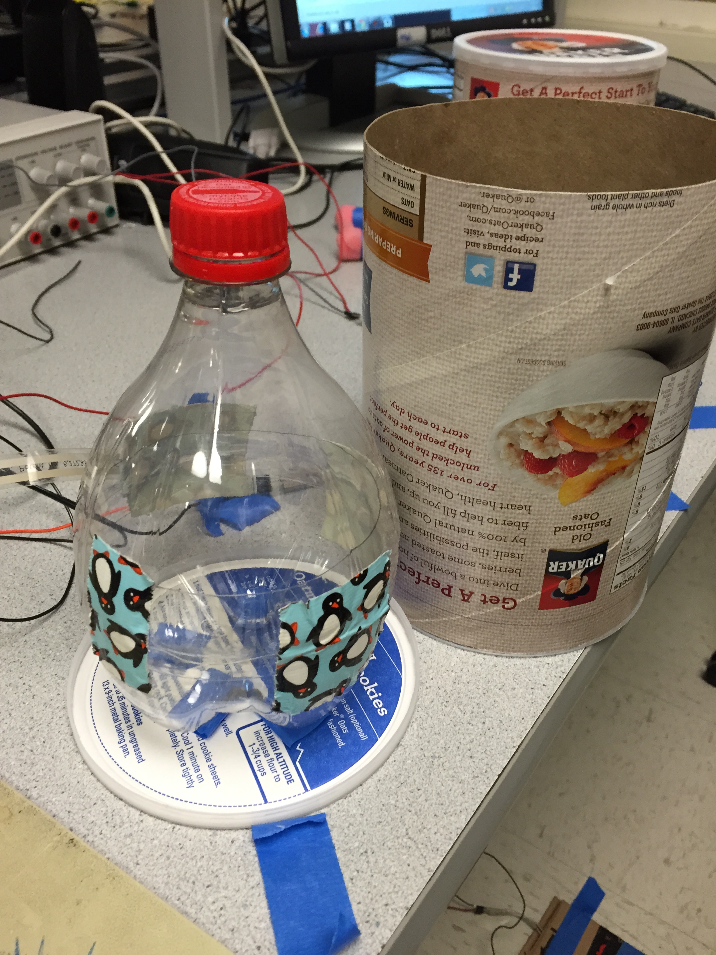
Each drum is made of a Flexiforce sensor, a cut 2-liter pop bottle, and an oatmeal container housing. The bottle is used to direct all of the force from the hit into the small sensor. The sensors are resistors that change their resistance based on the pressure that is applied to them. The bottle is suspended from the cover of the oatmeal container such that the bottle cap barely touches the surface of the table. This is done so that the sensor is not compressed when there is no hit on the drum head.
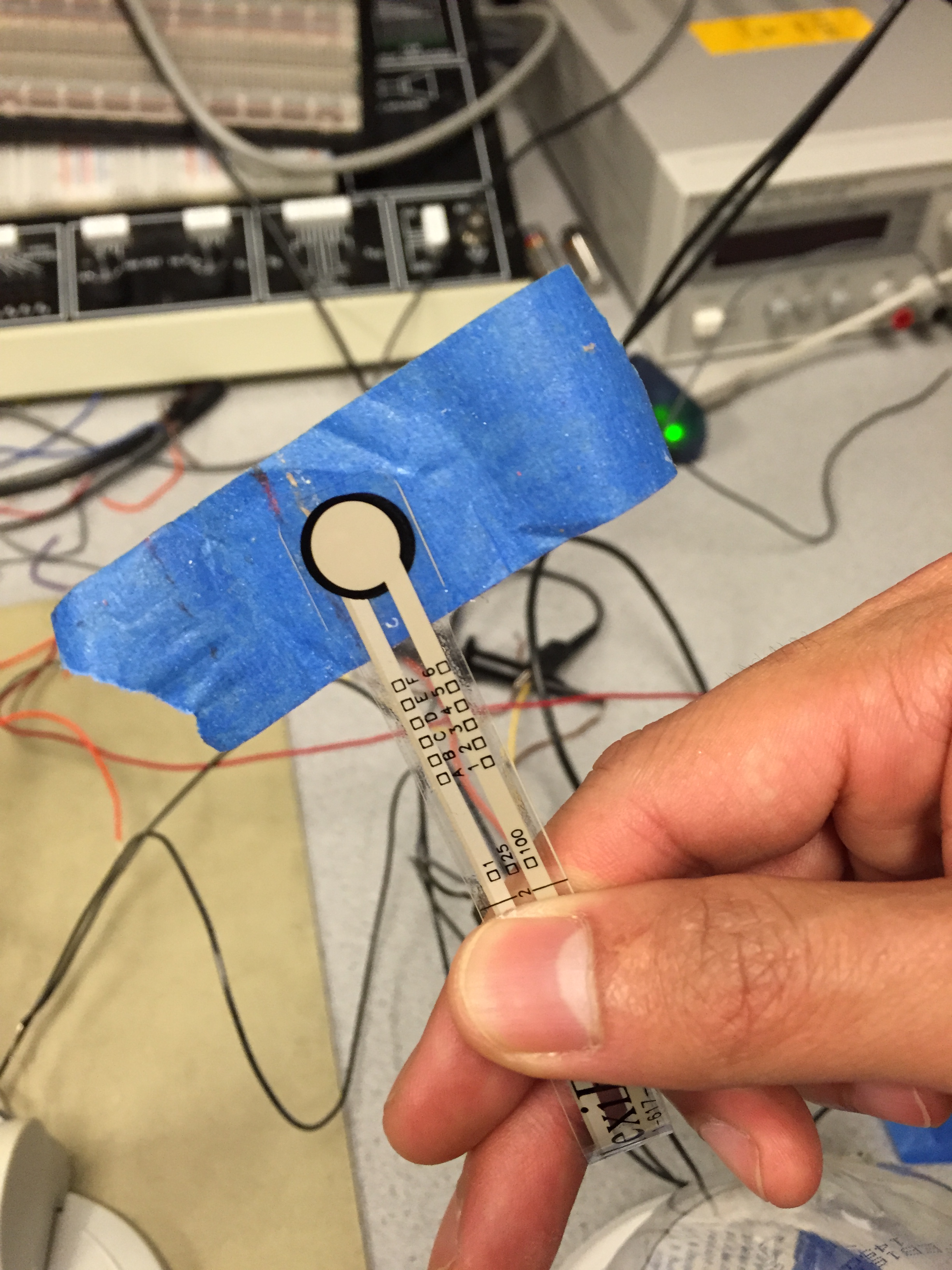
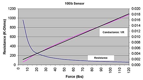
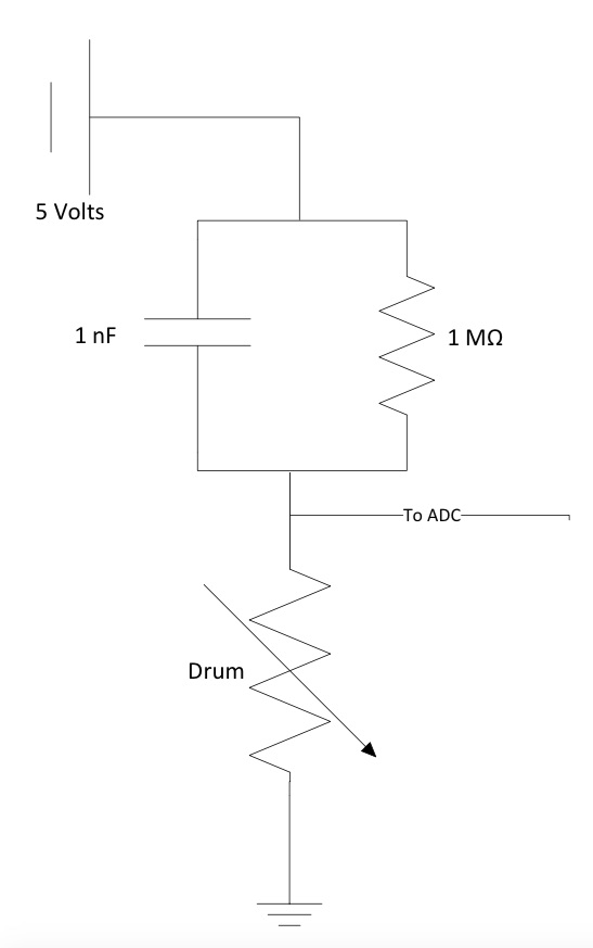
There are four drums and each of the sensors is connected to a channel of the MCU from pins A.2-A.5. Each pin is connected to a voltage divider where the force sensor is connected to ground and a 1MΩ resistor is connected to the 5 volt MCU Vcc.The value of the resistor was determined using this Force vs. Resistance graph from Tekscan for the flexiforce sensor.
It was discovered that input from one channel of the ADC would cause noise on a different channel so a 1nF capacitor was added across the 1MΩ resistor to stop the channel from registering a false hit.
The trickiest part of the hardware is the tuning of the drums so that the drum heads are sensitive enough to detect hits, but robust enough to not malfunction and return hits that weren’t actually hits on the drums. In order to register discrete hits more accurately, we debounced the drum inputs in software. We also covered the tips of our drumsticks with foam. This helped spread out the force transfer to the drums over a longer time period, making it easier to detect drum hits. It also made hitting the drums much quieter, which made it easier to hear the speaker output and helped prevent our project from driving everyone in the lab insane.
Software
Using the ADC, we polled one drum sensor every millisecond. If the input to the ADC is under the ADC threshold then a hit was registered from that sensor. We experimentally determined 190 to be an optimum value for the threshold. There are 3 different arrays of length 4 (our number of drums) needed for our project: hitState, hitFlag, and sampleLocation. The drum sensor at A.2 is mapped to index 3 of each of these arrays, A.3 is mapped to index 0, A.4 is mapped to index 1, and A.5 is mapped to index 2.
Each of the sensors is debounced in software such that a single hit is not registered as multiple hits. This is done using a standard finite state machine for debouncing. Debouncing was a tricky issue for drums constructed with very cheap materials, however. Hitting a drum quickly often causes extra force spikes due to the constructed drum continuing to move after impact, so we debounce the signal to remove this. However, a quick hit from a drum stick causes a very short signal spike, so we have to make sure we debounce quickly enough that this input is not ignored. We experimentally derived a state transition of 4 milliseconds for the debounce state machine. This means that we run our debounce code every millisecond, cycling through the drums one at a time.
Sound Output
Hardware
To play the drum sounds, an AD7303 DAC was used. The samples from each of the sounds is sent to channel A of the 8 bit DAC at 22kHZ using an SPI interface. The output of the DAC is connected directly to the speaker. Pin B.4 is connected to the clock sync pin on the AD7303, pin B.5 is connected to the MOSI input of the DAC and pin B.7 is connected to the SCLK input of the DAC.
Software
The samples that will be played through the speakers are contained in either the program memory or the flash memory of the MCU. If they are in the program memory, then the pgmspace library needs to be used to read each byte in memory. If the sample is in the flash memory, access to the sample array is carried out the same as any other access. We store the preprogrammed samples into program memory instead of flash memory because there is much much more program memory and we never have to modify the samples. This allows us to actually store a useable library of samples within the MCU’s memory space. There is an interrupt-triggered 22kHz ISR used to clock out each value of the sample through the DAC. The value is divided by 4 to allow for more than 1 sample to play at the same time. The playSlot data structure contains pointers to the arrays that will be played back. When a sample is played, it is loaded into an open playSlot and played back in the 22kHz ISR. The code that was written is based heavily on code in Bruce Land’s SPI site: http://people.ece.cornell.edu/land/courses/ece4760/SPI/DACspiGCC644.c
Microphone Input
Hardware
The mic is connected to the MCU through Pin A.7, which is the 8th input to the ADC. There is an amplification circuit and a low pass filter circuit as seen in the figure below. The filter we used was a MAX281 5-pole low pass filter. The amplifier used was the LF353 op-amp chip.
Software
To record the samples, we use an interrupt triggered at 22kHz. The same routine is also used to generate sound output because both of these applications must be triggered at the same rate. If the variable recordFlag is set when the ISR runs, we save samples coming in through the mic’s ADC input to a sample array. We also make sure not to start actually saving the sample until a reasonable amount of sound is being picked up by the mic. To let the user know that mic input is expected, we turn on a red LED when recordFlag is set. Due to speed limitations of the MCU’s ADC, we sampled at one third the interrupt frequency and only set every third byte of the recorded sample array whenever a value was read from the mic. In order to improve sample quality we performed some basic post-processing. This involved some simple interpolation between sampling points as well as including a ramp-up and ramp-down, roughly 4 milliseconds each, at the beginning and end of the samples. This ramping prevents clicking from occurring when the sample starts or stops playing. Due to hardware constraints we elected to only allow recording of four samples at any one time, one sample per drum. These samples are limited to 3700 bytes, or about 0.17 seconds. The length is limited because the recorded samples are stored in flash memory, which is very small. This allowed us to have a total of 4 samples, which is enough to map a recorded sample to each drum.
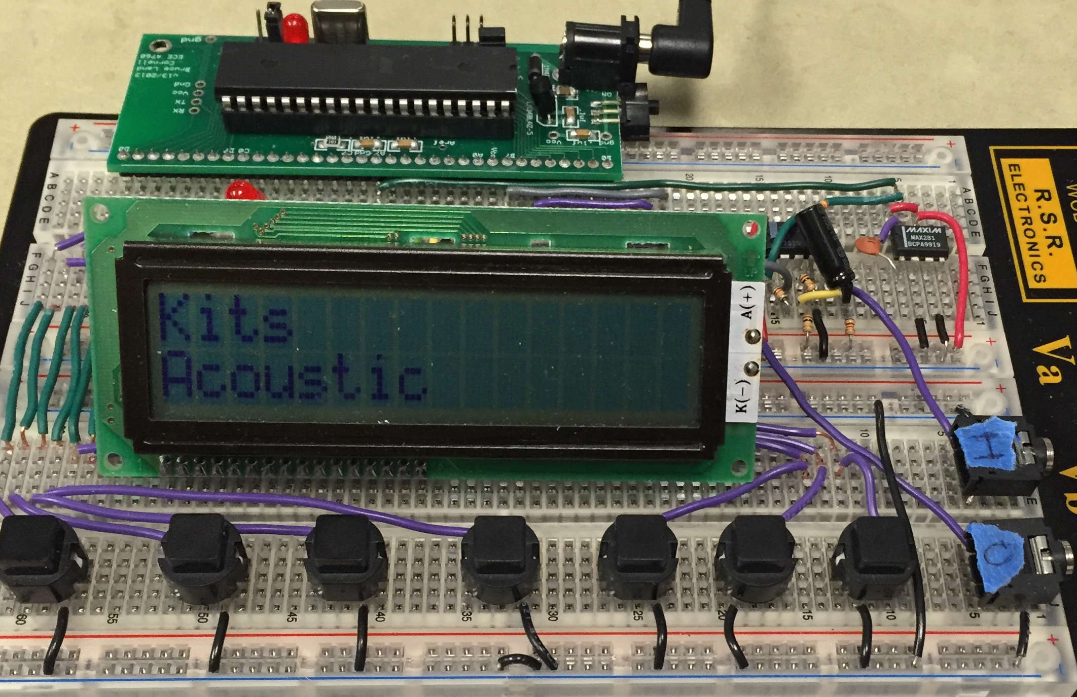
UI Buttons and LCD
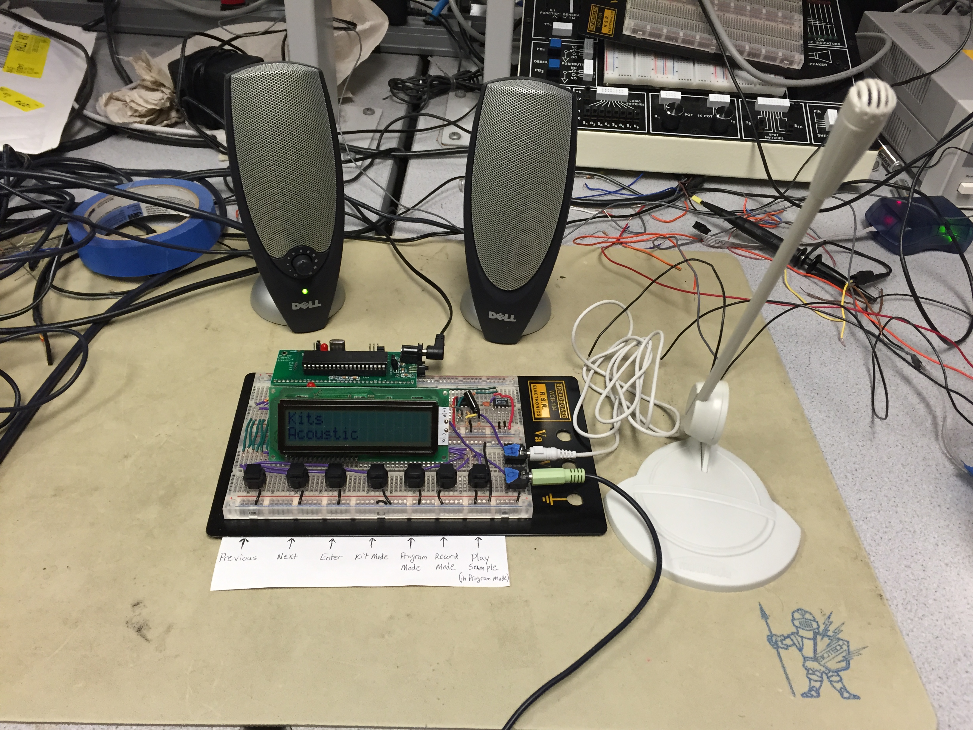
The User Interface for the drum set consists of 7 pushbuttons and an LCD display. This UI allows a user to choose between “Kit Mode”, which contains preprogrammed sets of samples forming a kit; “Program Mode”, which allows the user to program a specific drum to a specific sample in the sample library; and “Record Mode”, which allows users to record their own sound and program it to a drum. Our Kit Mode contained 4 preprogrammed kits: Acoustic (traditional drum sounds), Electronic (electronic drum-pad sounds), Misc (various claps, claves), and Smoke on Water (containing the four power chords used in Deep Purple’s Smoke on the Water). In Program Mode the user can scroll through all of the preprogrammed samples and play them using the play button before actually mapping a sample to a drum. Record Mode allows the user to record up to 4 samples for programming to the 4 drums in the system. Selecting a drum for mapping to a sample or recording is very intuitive and simply involves hitting the desired drum when prompted by the LCD.
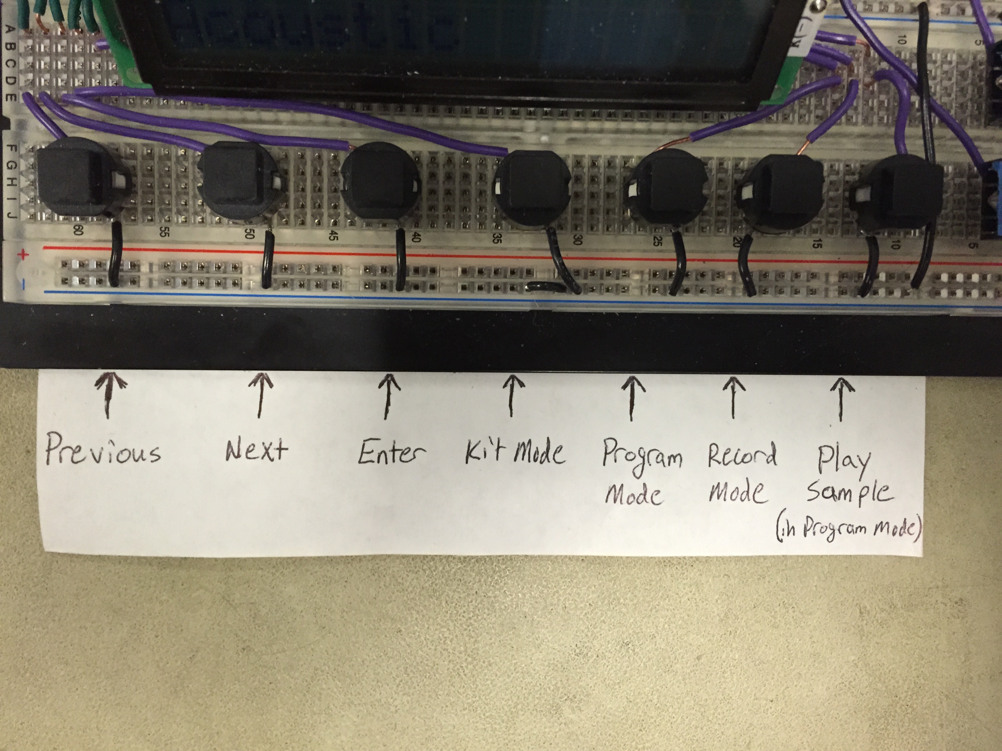
Users can interact with the system through the 7 pushbuttons, which are “Next”, “Previous”, “Enter”, “Kit Mode”, “Program Mode”, “Record Mode”, and “Play”. “Next” and “Previous” serve as navigation buttons, allowing users to scroll through the various kits/samples (depending on which mode they’re in). “Enter” allows the user to choose a kit or sample, and they are presented with a confirmation screen after hitting “Enter” that confirms the button push. “Kit Mode”, “Program Mode”, and “Record Mode” switch the user between the three modes of operation. Finally, “Play” allows the user to audition a sample in “Program Mode” before assigning it to a drum.
Results
Usability
There are some problems with accuracy of the force sensors. Sometimes the sensors will detect a hit when the drum was not actually hit and sometimes a hit will not be detected. This is because our drums were not built very precisely or with the highest quality materials. For the most part, however, the drums that were built were responsive to hits and very usable, especially the kick pedal and snare (yellow Wegman’s oatmeal container). The accuracy of the sounds created may not be as accurate as what would be created in real life. Also the quality of the recordings are not great either.
The design is very usable. The UI is intuitive and will explain what needs to be done by the user at every step. The mic will not start recording in record mode until it detects that a reasonable amount of sound has been detected.
Drum Hits
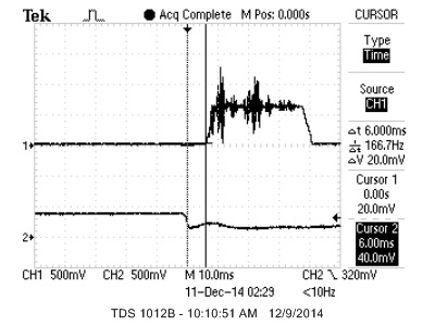
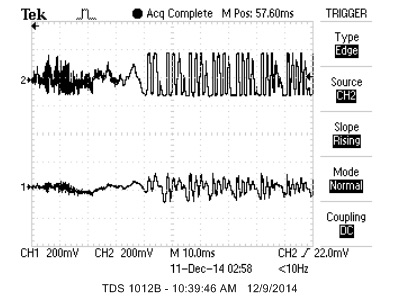
The latencies between the hits of drums and when the sounds played was well within acceptable ranges. The following figure illustrates the latency between hitting the drum head and the sound playing through the speaker. As shown in the screen capture, the latency from the hit to the sound starting to play is well below 10ms, which is when delays start to become apparent to the user. Channel 2, the waveform on the bottom, is the signal to the ADC pin connected to the drum. Channel 1, the waveform on the top, is the signal to the speaker
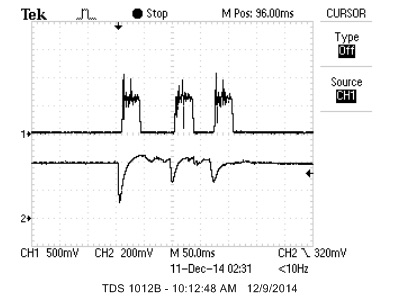
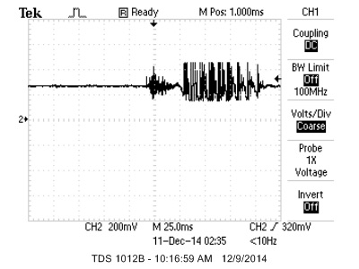
The system is also robust enough that it is able to get drum rolls, which are very fast drum hits in one smooth motion. There are three very clear peaks in the following image and each of those peaks is registered as a hit.
Recording
The recording through the mic required two different pieces, signal filtering from the mic to the ADC port and then saving the input to the ADC pin to flash memory.
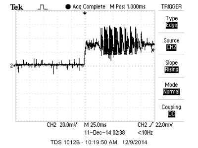
The following figure shows the input of through the mic vs the input the ADC pin. The raw input is channel 1 and the filtered output is channel 2. The channels are AC coupled to remove the DC offset. The raw signal is clearly amplified. Most of the noise that is filtered out by the circuit is very high frequency and difficult to resolve on the scope trace, but removing it through the low pass filter is necessary to produce cleaner recordings.
Because we are using a 22kHz playback, we needed to be able to record samples at 22kHz. This was difficult because the ADC on the ATmega1284 was too slow to record at 22kHz. The fastest it would go was around 8kHz. The following 2 figures shows how well the interpolation works in our system. The general shape of the signal is replicated through our interpolation. Some of the higher frequencies in the beginning were not able to be replicated because of the slower sampling rate and the fact that they were cut off by the ramp-up function.
Conclusions
The results met most of our expectations. In the beginning we had wanted to make it so that the drums would be able to play sounds with different volumes based on how hard the drum was hit. However, as we built up the project, it became clear that this was an unrealistic goal. This is due in part because of the way that force is transferred to the force sensor and also because of the way that the drums are constructed. Areas of the drum that are directly connected to the the soda bottle would transfer almost all the force to the sensor while other areas might not transfer as much. Also each drum is constructed differently and the force to each sensor would not be consistent.
If we were to do this project again we might try harder to create drums consistently so that we would be able to add varying volume to drum hits. It might also have been good to use a 10 bit DAC instead of the 8 bit DAC that is currently in the project. This would increase the resolution of the sound coming out of the speakers and allow us to take advantage of the 10-bit ADC resolution.
Intellectual Property
We reference code from the Step Sequencer Drum Machine project from Cornell’s ECE 4760 from 2011. Also, we referenced code from Bruce Land’s SPI page that uses the AD7303 Digital-to-Analog Converter. This code was very helpful in playing samples from our microcontroller without performing audio synthesis onboard. All the rest of the code was written by us and we do not feel that we are infringing on anyone’s intellectual property by building our project.
While our project could be seen as reverse engineering an actual electronic drum kit product, we were making most of the functionality from scratch and did not use any real product as a basis for our engineering. We did not find any patents that we are violating.
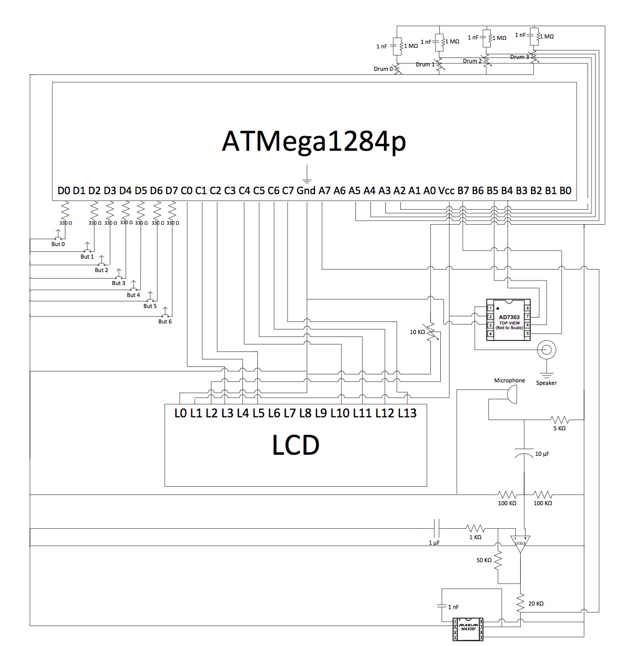
Full Circuit Schematic
Appendices
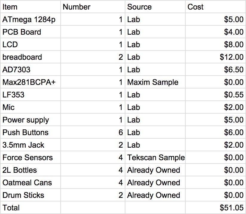
Appendix A: Budget
Appendix B: Sources
SPI Reference: http://people.ece.cornell.edu/land/courses/ece4760/SPI/index.html
Step Sequencer Drum Machine: http://people.ece.cornell.edu/land/courses/ece4760/FinalProjects/s2011/aps97_df257/aps97_df257/index.html
Flexiforce Information: http://www.tekscan.com/flexible-force-sensors
Maxim Integrated: http://www.maximintegrated.com/en.html
Appendix C: Project Management
Every task was a team effort. No task was left up to any single or even pair of team members. Every system that was built was truly a collaborative effort. There were very few lab hours that involved only one of us. If we had to break up management into different tasks that we each put the most effort into, it would be as follows: Nick-Drum Technician, Roshun-UI, Ian-Systems Integration.