Contributors: Michael Nguyen (mmn43), Elias Wang (ew429), Tri Hoang (tmh252)
Introduction
This project aims to create a .WAV music player with a parametric equalizer and adaptive noise cancellation. We decided to pursue this as our final project for ECE 4760 (Designing with Microcontrollers) because it aims to implement severally technically intersting signal processing techniques in C.
High Level Design
We will be attempting to build a microphone system capable of actively cancelling out ambient noises, and providing an equalizer for variable frequency gain. The system’s peripherals will consist of an SD card to read in the appropriate song, user input commands through UART, a microphone to record ambient sounds, and a playback device to output the desired signal. We will be using the PIC32MX250F128B as the microcontroller and will be implementing the equalizer, noise cancellation, and output playback in software. We decided to custom build our microphone circuit utilizing a series of high gain amplifiers and voltage buffers. In order to record background noise, the input signal from the microphone must be amplified to a point where ambient white noise can be resolved by the microcontroller’s ADC. Ultimately we would like the device to be portable and so the microcontroller along with its other hardware components will be battery powered. In the end, due to time constraints, we adapted our project to become a noise cancelling microphone system with equalization, where the background noise would be filtered out while someone was speaking into one of the microphones and the final output would be the voice signal passed through an equalizer.
Logical Structure
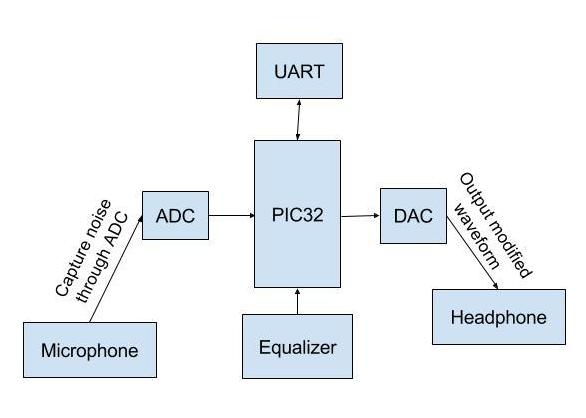
We obtain two audio inputs from two separate microphones. One is a noise reference while the other is a noisy signal. These two are used as inputs to the least mean squared (LMS) filter for the noise cancellation. The data is captured via alternating input ADC reads. After obtaining the samples, they are fed into the LMS algorithm that outputs the desired, de-noised signal. This is then fed into the equalizer where certain frequency bands are amplified or attenuated. Finally, the resulting signal is outputted through the DAC to an 3.5mm audio jack.
High Level System Block Diagram
Hardware/Software Tradeoffs
Noise cancellation and sound equalization can both be done in either hardware or software. However, since this is a microcontroller class, we decided to implement the signal processing in software on the PIC32. Although it is possible to amplify the microphone signals in software, the hardware circuit allowed us to do it more easily, while also reducing some noise.
Math Background
Noise Cancellation
The simplelist method of noise cancellation works by adding the noise, phase shifted by 180 degrees, to the signal in order to cancel the noise through destructive interference. However, this method is not very robust and relies on the noise signal being exactly the same in the reference and primary signals. Therefore, we decided to use a Least Mean Squares (LMS) filter for the noise cancellation. This works by adaptively estimating a filter that mimics another filter by minimizing the mean squared error of the difference between the actual and predicted signals.
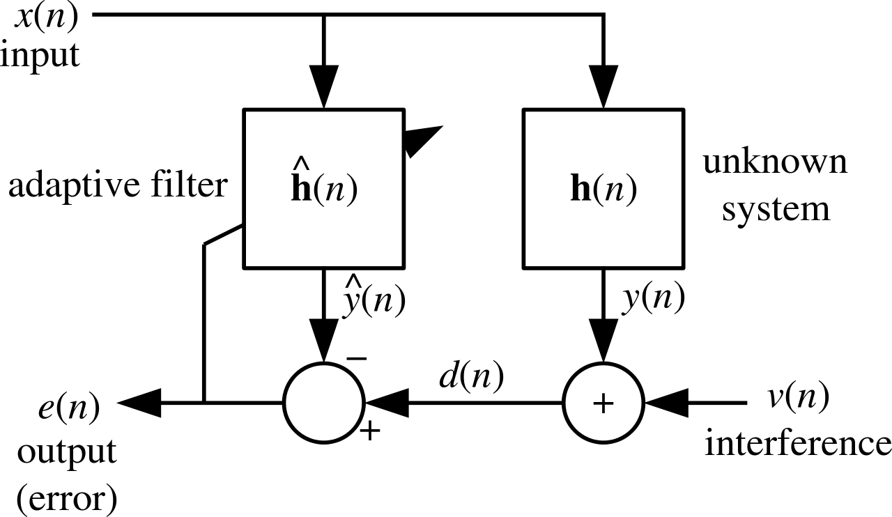
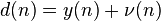
In the diagram below, x(n) is the noise reference obtained from one microphone and d(n) is the primary signal obtained from the other microphone, contains the voice signal, v(n), and the modified noise, y(n). Since the noise from the reference microphone, x(n), is not exactly the same as the noise in the primary signal, y(n), we must find a way to model y(n) in order to remove the actual noise in the signal. The LMS filter solves this by updating the weights of the estimated filter from the error signal. Ideally, this filter will converge to the unknown system and y_hat(n) will approach y(n), thus making the error signal, e(n), converge to the voice signal, v(n), successfully providing noise cancellation.
The LMS algorithm for a pth order algorithm can be summarized as:
Parameters:
Initialization:
Computation (for n = 0, 1, 2, ...):


(source: https://en.wikipedia.org/wiki/Least_mean_squares_filter)
Equalizer
We implemented several FIR bandpass filters using the Parks-McClellan algorithm which calculates the weights for the first N (alpha = 0 to N) elements of the following transfer function:
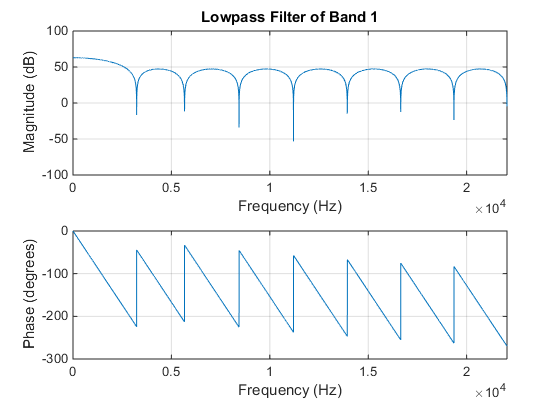
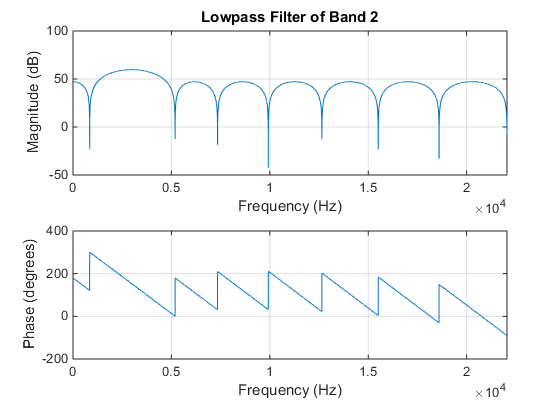
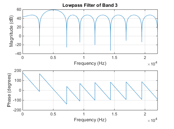
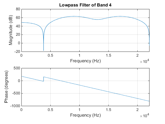
We chose to use an FIR filter due to its linear phase. And so, we should hear little to no distortion at the output due to phase. The coefficients were calculated initially using MatLab’s methods “firpmord” to optimize the algorithm’s parameters and “firpm” to calculate the “p” coefficients as specified by the equation above. The passband and stopband were specified to have 20 dB separation. The ripple for the passband was fixed at 5 and 15 dB respectively. Using the following frequency ranges specified by the table below, we found the following frequency response assuming equal contributions from each filter bank:
The frequency bands are quite large because we wish to minimize the amount of computations during run time. Therefore, we chose these parameters so that the equalizer will, at worst, be a 18th order filter. Below are the frequency responses of each band computed from MatLab:
Hardware Design
Overview
The device will utilize the PIC32 for input/output signal analysis, an external DAC, and two microphone circuits to pick up ambient noise and the desired signal + noise. The microphone circuit consists of a LM386N-1 Low Voltage Audio Power Amplifier and an MCP6242 operational amplifier as a voltage buffer. The audio amplifier will provide the necessary boost so that the PIC32 can resolve the sound while the voltage buffer will ensure the voltage does not exceed the pin’s limitations. Each audio signal will then fed into the PIC32’s 10-bit ADCs and filtered in software. The PIC32 will communicate with the computer via UART using one of the microcontroller’s SPI pins. UART will be used to tune the equalizer parameters. After the signals have been appropriately filtered, the result will be sent digitally to the external DAC via the PIC32’s second SPI channel. The analog signal will then be played out through an audio port.
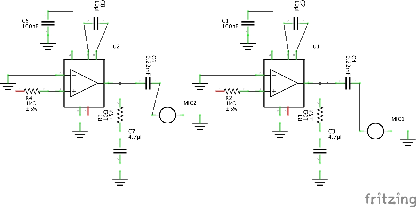
Microphone and Amplifiers
As mentioned above, the two identical microphone circuits consist of a LM386N-1 Low Voltage Audio Power Amplifier for gain and a MCP6242 operational amplifier for a voltage buffer. The microphone itself provides approximately 20 mV peak to peak signals for close loud noises. And so, we chose to fix the gain at 200 (output at 4 V see schematic below) so that we may resolve small fluctuations in voltage due to noise. This gain, however, may be problematic with even louder noises (e.g. tapping the microphone) which bring the voltage to approximately 6V peak to peak after the amplifier.
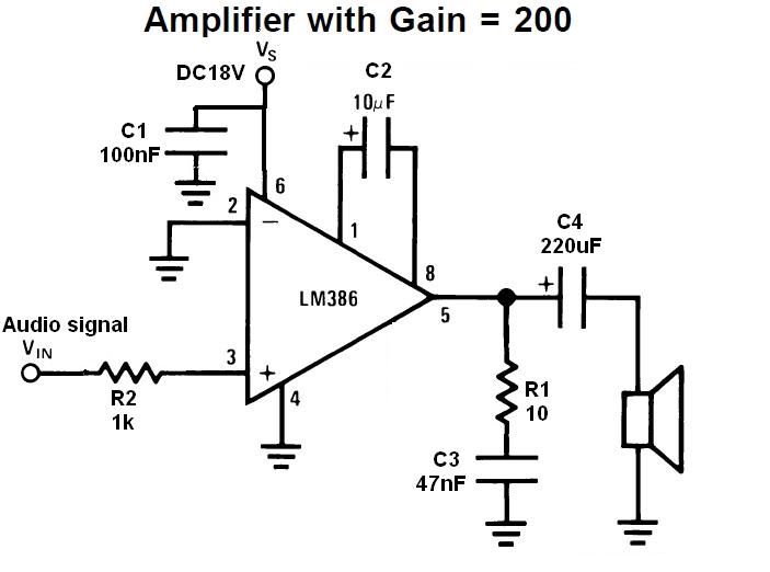
Amplifier Schematic Design (source)
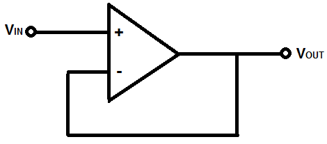
This is problematic as our pin can handle approximately 3.3 V at the input pin. Therefore, to prevent the pin from burning out, the voltage buffer (see figure below) was added with 0 to +3.3V rails between the amplifier and speaker and the input to the op-amp is biased at 1.5 V.

Voltage Buffer (source)
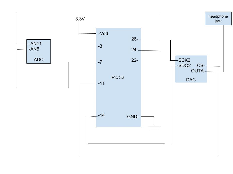
PIC32 ADC and External DAC
For the ADC, the primary signal from the microphone was connected to pin 24 (AN11) and the noise reference from the other microphone was connected to pin 7 (AN5). The DAC SPI uses two ports. SCK2 is connected to pin 26 and SDO2 (MOSI), included in PPS output group 2, is connected to RB5 which is pin 14. CS (chip select) connected to RB4 which is pin 11.
Software Design
ADC for the Microphone Inputs
We also were able to set up alternating input ADC capture to sample from both microphones. This allows us to use one microphone as the signal+noise source and the other as the noise reference. These two components are necessary for the LMS filter.
The ADC was set up with the following notable configurations: auto-convert on, auto-sampling on, scan mode off, 2 samples per interrupt, alternating input on. The full setup can be found in the Appendix. We also defined AN11 (pin 24) as the input for A and AN5 (pin 7) as the input for B.
We perform the ADC read in the timer 3 ISR, which runs at the defined sampling frequency. In the ISR, we read from buffer 0 into the variable for the primary signal (signal+noise) and from buffer 1 into temp variable which is used to update the reference signal (background noise). The update function simply adds the new ADC value to the end of the array while shifting out the oldest value.
Noise Cancelling
We implemented the LMS algorithm for the PIC32, based on our MATLAB simulations. The LMS algorithm was done in the same ISR as the DAC output, which was controlled by timer 4 and also ran at the same sampling frequency. This was to simplify the code and make sure no up or down sampling was needed.
Four variables were used in our implementation: two integers for the primary and desired signal, a integer array for the reference signal, and a float array for the filter weights. The order of the filter determines the length of the arrays. We initially decided to implement fixed point arithmetic for the weights; however we ran into problems properly implementing fixed point and ensuring the system stability and so we decided to settle for float.
The first step of the algorithm is calculating the desired signal at the current time instant. This is the same as the error signal and is obtained by subtracting the primary signal by the predicted noise. The predicted noise is the inner product of the weights and the reference signal. We created a simple helper function to calculate the inner product. The desired signal is the output of the LMS filter and can be sent directly to the DAC or put through the equalizer.
During each iteration we also need to calculate the weights for the filter. We did this by looping through the weights array and adding the product of the step size, corresponding reference signal value and desired signal value to the current weight. The implementation can be easily understood by looking at the first few lines of the timer 4 ISR.
Equalizer
Using the coefficients computed using MatLab, we implemented the FIR filter by simply coding a function for convolution, and keeping track of the previous 18 outputs using an array. To calculate the desired filter, the coefficients of each bandpass filter are weighted differentially and added together depending on the amount of gain the user wants for each frequency band. By applying the convolution on the array of outputs and coefficients, we can now generate the filtered output.
DAC Communication
Most of the software necessary for the DAC was just setting up the pins to function as described in the hardware section. To actually send the data in the ISR, we first set the CS to low to start the transaction, waited for the DAC to be ready, wrote the audio data to the DAC, waited for the transaction to finish, then set the CS back to high. Before sending the data, however, we made sure that it was within the 12-bit range of the DAC to prevent any clipping.
Results and Conclusion
Conclusion
Overall, the results that we obtained matched the majority of our expectations. We have finished a microphone system with an equalizer and adaptive noise cancelling feature in. The equalizer works really well but we did not have enough time to implement the UART communication with the PIC32 that would allow users to change parameters in real time. Every time the users want to use the equalizer and change parameters, the code has to be flashed to the micro-controller again. The adaptive noise canceling feature that we implemented also works somewhat as expected. We simulate the noise-cancelling features. The system will take inputs from two microphones as follow: one will record the main sound source, the other will record a sign wave. As end-users who use the headphone, we were able to experience that the noise was canceled.
Without prior experience with adaptive noise cancelling filters, in hindsight we were a bit optimistic about our ability to implement one. In the end, we were able to get the algorithm working, although not as robustly and accurately as we would have liked. The equalizer was relatively easier, partly due to our increased experience designing bandpass filters.
Noise Cancellation Results
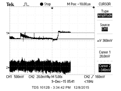
The LMS noise filter worked somewhat as expected. The waveform below shows the output of the LMS filter with a sinusoid input to both microphones. We see the filter converge and the output fall to zero. Since there is no voice signal, the output should just be silence. We see about a 20 dB reduction in amplitude of the sinusoid background noise.
We were surprised that the filter performed decently with different types of broadband noise sources. With a low order filter we expect the cancellation to be narrowband and quite limitted. When observing for ambient noise, there was very little to none. We tested to see whether or not this was due to the resolution of the ADC which was filtering out the noise; however, we found that the resolution was high enough to pick up the noise. It may be possible that because of the low sampling rate of the ADC the filter would be more effective in filtering out broadband noise.
Equalizer Results
The only change we made when producing the filter coefficients was decreasing the slope of the bandpass filters. By having softer edges, the number of coefficients needed decreased to the desired 18 coefficients. The equalizer was tested by inputting a sinusoid into the primary ADC port and grounding the noise reference. From there, we measured the power content of the specific frequency given a frequency in-band and a frequency out of band. To test each band, we selected the center frequency of each band and a frequency 1 kHz out of band.
We found that in general there was a 19-22dB drop between the in and out of band power content given the same input amplitude.
Future Changes
If time permits, we would implement a more interactive UI with the users. At the moment, the only way to make use of the equalizer is to flash the code to the PIC32 again. We would want to allow users to instantaneously change the parameters of the equalizer through UART. Moreover, we could turn this into a music player with noise-canceling feature. The music is stored in the microSD card which will be fetched into the PIC32. MicroSD connector will connect with PIC32 through SPI channel.soft
Societal Impact
The product is a microphone with adaptive noise-cancelling that will reduce background and an parametric equalizer. This project include a software equalizer, microphone, headphone and a board of circuits (the system). Because the equalizer will only send inferenced signals, we identify little to no probable hazards that could stem from repeated use of a headphone held next to the ear.
Standards
SPI protocol which was used to communicate with the DAC, was the only standards that we used.
Intellectual Property Considerations
We use code from lab 2 and 3 to set up the DAC in the course. We referenced code from our TA Syed Tahmid for setting up the ADC as well. We did not sign any non-disclosure to get a sample part.
Ethical Considerations
IEEE code of ethics are something we carefully considered during the course of working on this final project in ECE 4760. We strictly ensured the IEEE Code of Ethics is always followed. We confirmed that neither ours nor the user’s safety is at risk while working on the project. There are no high voltage/current sources that could wounded a person using our project. Therefore, there are no safety measures conducted. We kept our lab space clean and minimal.
We referenced code from ECE 4760 website in order to avoid conflicts of interests. We used glasses when perform soldering. We are not unfair with anyone based on race, religion, and national origins. We treated our peers with respect and did not use any curse words towards anyone or while doing the lab. We cited all contributions made to the project including any of our own previous work. The lists of cost assessments were truthful to our knowledge and we did not try to cover any potential costs.
Overall, this project was created with the intent to apply filtering and adaptive noise cancelling algorithm in a real product. In the end, we gain a valuable understanding in a field of signal processing. We have cited the contributions of others and taken criticism of our work.
Legal Considerations
As far as we know, there are no legal considerations involved. All pictures and diagrams without a reference are drawn by ourselves. All references we have used have be indicated. All materials used were purchased by us or taken from lab with permission.
Appendix
Appendix A - Program Listing
Source code can be found in the following repository (see Lab5): Source
Appendix B - Schematics
PIC32 Schematic
Microphone and Amplifier Schematic
Appendix C - Cost
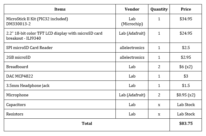
Appendix D - Contributions
Appendix E - References
PIC32 Microcontroller