Software Design
The software side was completely done in protothreads with some additional helper functions. There were 4 threads: the LCD update thread, the keypad thread, the timer thread, and the water control thread, all of which was initialized in the main function.
LCD Update Thread
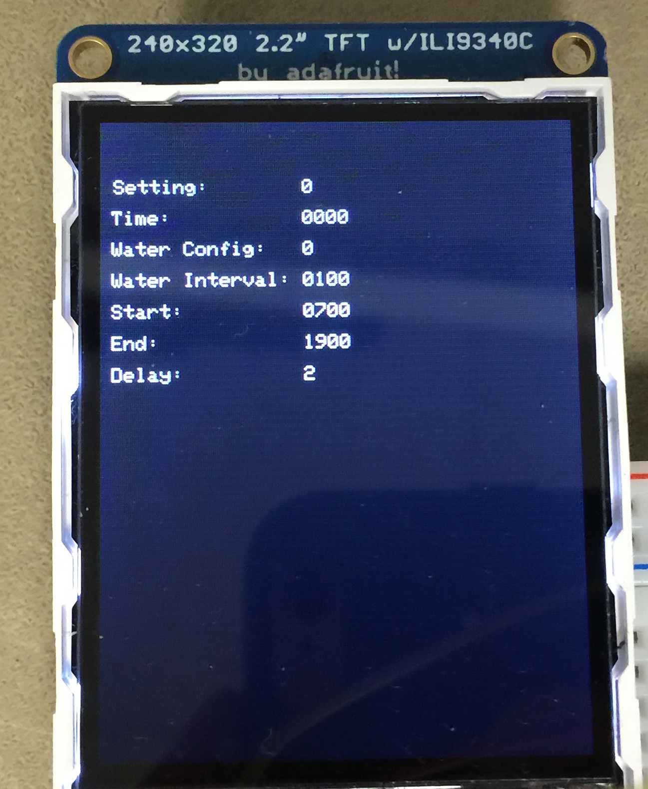
The main function of the LCD update thread was to update the LCD with the current values of all the configuration options and the time. This was done by first programming one half of the LCD to display the variable names. Afterwards, the half with the variable names would not be erased or reprogrammed. Instead the LCD will program the other half with the updated values. The LCD would update every 500 milliseconds.
Keypad Thread
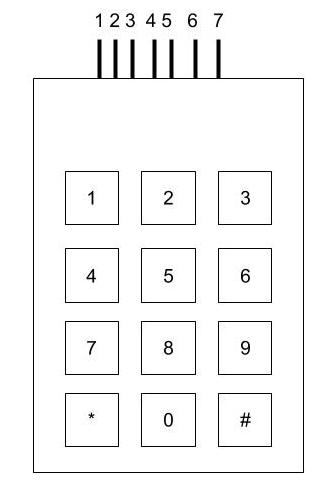
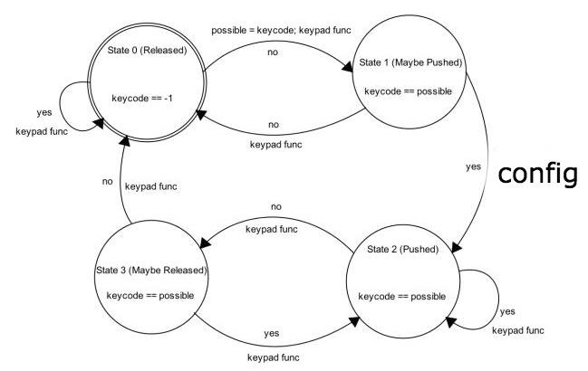
The keypad thread was exactly the same as the code used in Lab 2 for the DTMF dialer, except that the maybe state of the FSM changed what it did to the variables. The FSM used was the same FSM used in Lab 2 provided by Bruce. As in Lab 2, the keypad thread would be scheduled approximately every 30 milliseconds. First it would call a helper function to scan through the keypad to scan for a value greater than 0 to indicate that a key was possibly pressed. The value was checked against a table of values for all the keys and if it matched, the table index would be returned. Once this was done, the keypad thread would proceed through the 4 state finite state machine to handle debouncing. In the second state, the maybe pressed state, if the keycode matches the previously read keycode, then depending on the keycode, a different option will be selected. If the key pressed is the * key, the system will cancel any ongoing changes to the configuration values. If the key is a number from 0-9 and setting is 1, the thread will call the helper method config to change the settings appropriately. If the value being changed is a time, the key will be checked to see if it matches the constraints of the place and if the buffer is full. If the buffer is full, the time will be converted to the proper format and stored. Otherwise, the key will be added to the buffer and setting will remain unchanged to indicate the option is not set yet. If the key is the # key, then setting will be changed to 1 indicating that the user would like to change a configuration option. Otherwise, setting will be set to 0 indicating that it was a random key press and nothing should change. The FSM used in the keypad thread is displayed below.
Timer Thread
The timer thread would simply yield for 1 second. After which it would update the elapsed system time. Once the elapsed system time is greater than or equal to 60, the minute variable would be updated. Once the minute variable was greater than 60, the hour variable would be incremented. During each call, a check would also be performed to ensure that the hour and minute are stored in the proper format from 0000 to 2359. Minute and hour were stored separately to reduce the number of calculations that would need to be done. Additionally, all time values were also stored as minutes to simplify calculations for the water control thread.
Water Control Thread
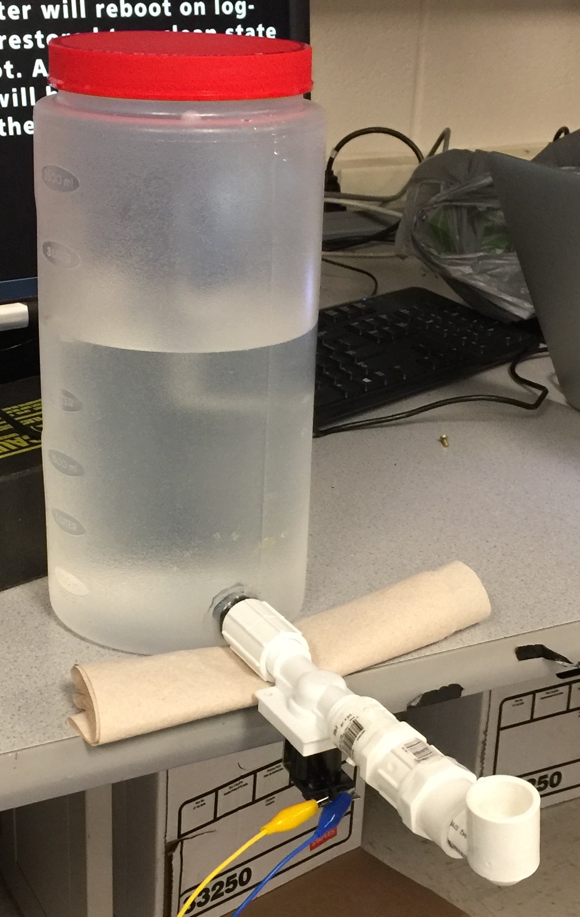
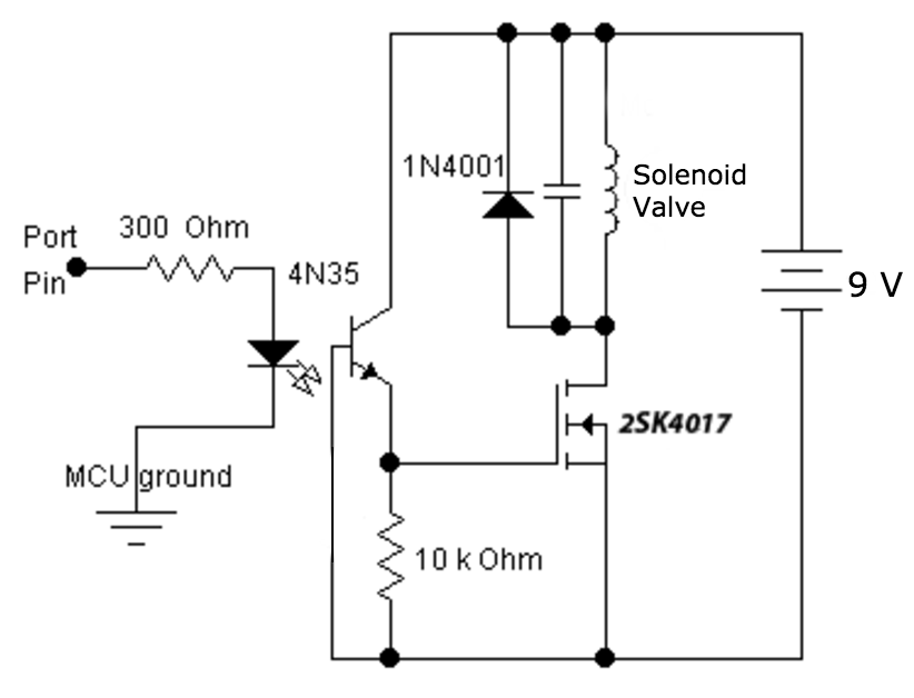
The thread would first check if the system was in manual or timed mode. If the system is in manual mode, the thread will check if the button is held down and the solenoid valve is off. If so, it will set the solenoid pin to drive the valve and wait for a period of time. This is to allow the valve to actually open before allowing the thread to close the valve. The second condition that is checked in manual mode is if the valve is open and if the button is released, If so, the pin will be cleared an the thread will yield.
If the system is in timed mode, the thread will check if the (current time - start time) % interval is equal to 0. If it is, the thread will drive the pin high, yield for startup, then yield again for the duration based on the delay value, before clearing the bit and yielding once more for the shutoff time. Afterwhich, the thread will yield for a minute as it will not be time to dispense water again. If it was not equal to 0, the thread will simply yield for a minute and then check again.
Main Function
The main function simply sets all of the appropriate pins as input or output pins and sets the default values for all the configuration options. Once this is done, the TFT and the protothreads are initialized, then the system schedules the protothreads.