Cornell University ECE4760
Realtime clock and Calender (RTCC)
PIC32MX250F128B
Realtime Clock
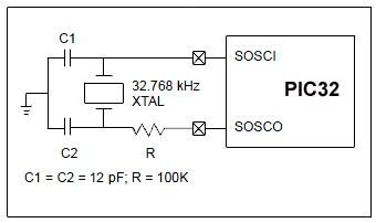
The realtime clock and calender (RTCC) maintains time-of-day and date based on an external 32768 Hz crystal or oscillator. The datasheet suggests using a crystal, but don't! The choice of capacitors is too critical for easy prototyping. Note that most solderless prtotype boards have too much capacitance for an external crystal, which requires around 12 pf of load capacitance. Typically, each side of the crystal would have a 12 pf capacitor to ground and would be connected to SOSCI and SOSCO (pins RB4 and RA4). The crystal circuit is shown below but is very sensitive to stray capacitance. You will probably have to tune the frequency using different capacitors, and the one second pulse as discussed below.
Rather than use this circuit, use the oscillator system described below.
It is easier to set up and more stable, and may draw less power.
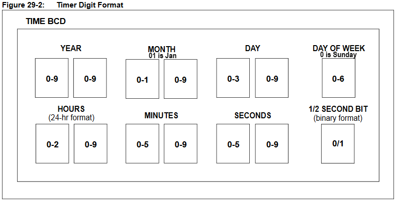
Setting up the RTCC is easy, but remember that the time and date registers store data in BCD format! The lowest 4 bits store the first decimal digit, the next 4 bits the second decimal digit, so that decimal 10 is stored as 0x10 and decimal 18 is stored as 0x18. See the reference manual chapter and PLIB chapter 19 for details on time/date format and setting the time. The details of the BCD storage are shown below. Note that the Day-of-the-week is zero based, but month is 1-based.
Instead of using a crystal, I strongly suggest that you use an external oscillator module which can be connected to SOSCO (RA4) through a 1K resistor. (For comparison, the internal oscillator draws about 25 microamps (datasheet TABLE 29-7). Accuracy is then determined by the external crystal, in the range of ±5 to 50 ppm. )
-- For example digikey part number DS32KHZS#T&RCT-ND. See example project using this module.
This part draws about 150 microamps and has a frequency accuracy of ±2 ppm (equivalent to ±1 min/year).
--
A smaller, lower power part is the SiTIME SIT1630AI-S4-DCC-32.768E (digikey 1473-31301-1-ND)
This part draws 2 microamps and has a frequency accuracy of ±20 ppm max (equivalent to ±10 min/year).
According to the data sheet, most parts fall in the range ±5 ppm when maintained at about 20-25 C (equivalent to ±2 min/year).
Remember that you must make sure the config_1_3_2.h file is set so that the secondary oscillator is turned off:
#pragma config FSOSCEN = OFF
This is because
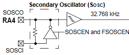
the internal oscillator is not actually used. Instead, you wire the external oscillator to the output pin of the internal oscillator, SOSCO (RA4) through a 1Kohm resistor. With the oscillator turned off, the internal circuitry floats this output. The schematic of the internal circuitry (below) shows a tristate-driver which is controlled by FSOSCEN, and a resistor which has a value of around 2 Mohm. You can see that driving SOSCO makes a direct connection to the clock output schmitt trigger.
An example code turns on the clock, sets the time/day at boot-time, sets up a 1 second RTCC pulse on RB3,
then reads three different time estimates, plus clock time:
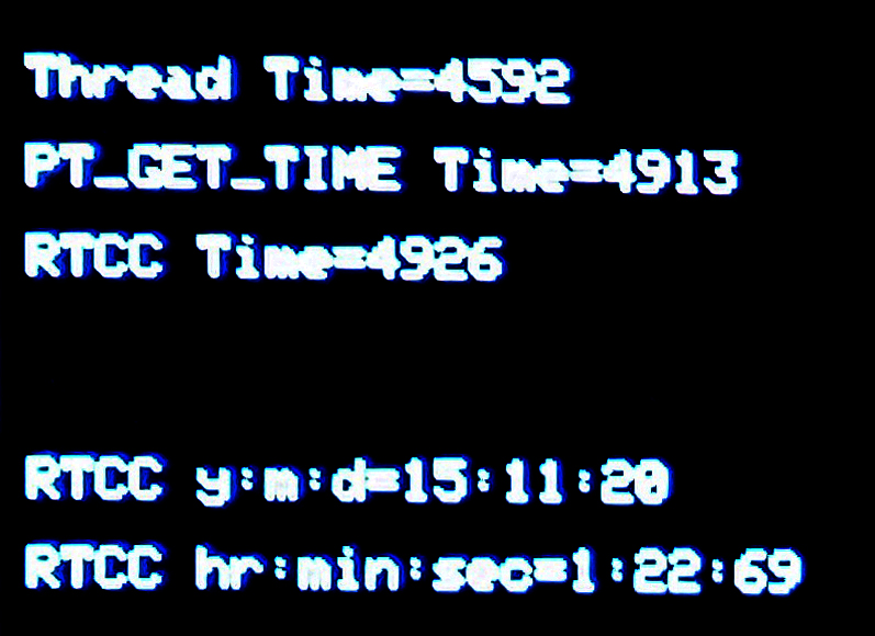
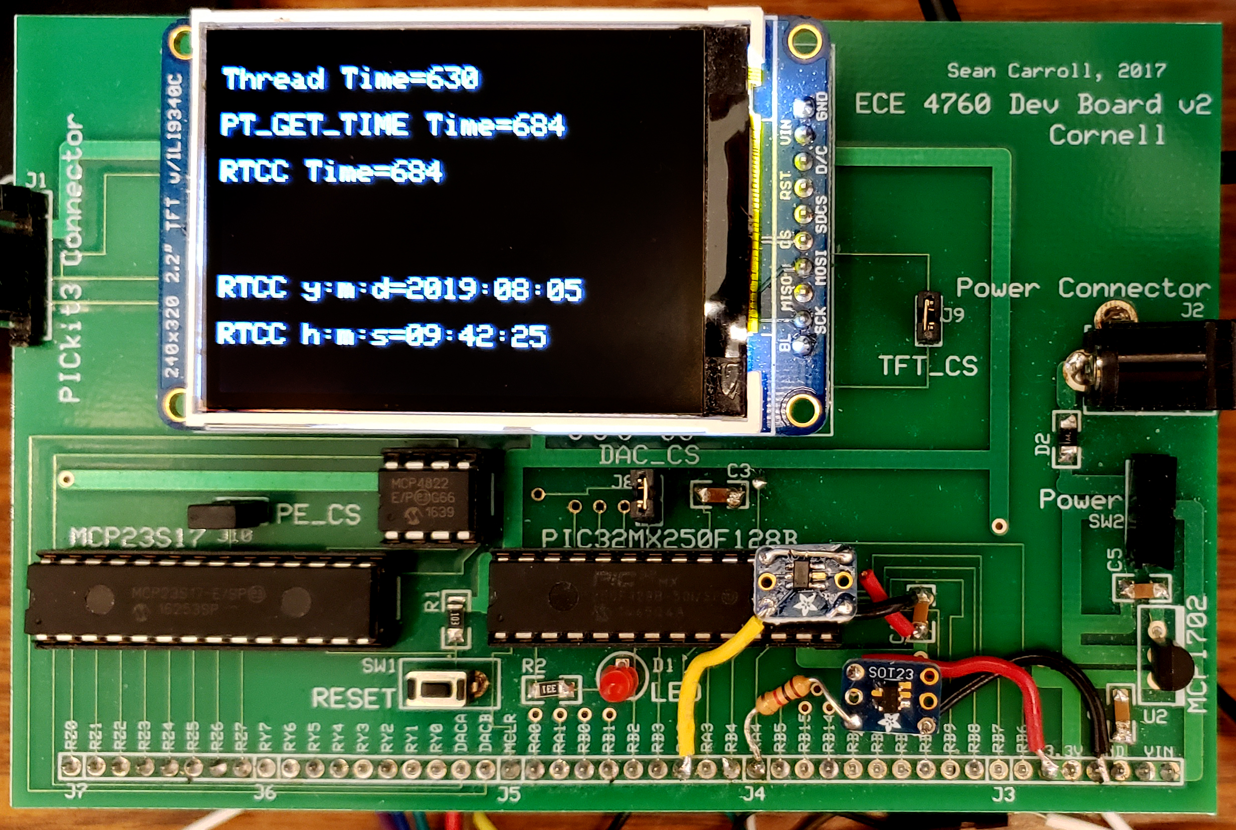
As you can see in the screen dump below, the ISR-driven timer (SYSCLK is derived from the internal RC oscillator) was about 0.26% slow compared to the RTC oscillator. This number is within the published error range of the internal RC oscillator. The ISR-driven timer would be about a day off after a year of real-time (and in fact overflows after about 2 months). The thread time was low by about 6.8%. So the thread time is completely useless for a realtime clock. The RTCC is the only way to get a reliable, long term clock. BUT you must test the elapsed time on the RTC. Even if the oscillator is accurate and stable, there are small systematic errors which can creep in. I used the one second output time pulse from the RTC to make sure the oscillator was set up correctly. The oscilloscope measure function should give exactly 1.000 Hz. If it reads something like 1.004 Hz, then the oscillator setup is not correct!
Switching SYSCLK to use the primary external oscillator input in the config_1_3_2.h file
#pragma config FNOSC = PRIPLL, POSCMOD = EC, OSCIOFNC = OFF
and connecting a 8MHz oscillator to OSC1 (bottom of timers page) makes the ISR-driven PT_GET_TIME() millisecond count almost as accurate as the RTC. The seconds count matches for at least 10000 seconds when using the two external oscillators. After 333600 seconds (~3.9 days), the PT_GET_TIME() millisecond count lagged by 10 seconds, or about 30 ppm. Since the accuracy specification on the RTCC oscillator is ±20 ppm and on the 8MHz oscillator ±30 ppm, the two counts match within spec. The RTCC differed from internet clock time by about two seconds in 4 days (10 ppm). The image below shows typical counts, as well as the connections for the two external oscillators. The RTCC oscillator is a SiTIME SIT1630AI-S4-DCC-32.768E (digikey 1473-31301-1-ND) on an Adafruit SOT-23-5 carrier board. The 8MHz ocillator is mounted over the end of the PIC32. The RTCC oscillator is to the right and lower in the image.
(Code)
Older, possibly obsolete, code:
For testing, the following code initializes the clock and produces a 1 Hz square wave at pin 7 to check crystal accuracy. If you use a crystal rather than an external oscillator you must do this. An example code starts the clock and sets it in main, produces a 1 Hz square wave and also reads it in the serial command thread. As usual, you will also need protothreads to run this.
// init the clock
RtccInit();
RtccSetTimeDate(0x0, 0x0); // for testing accuracy
RtccSelectPulseOutput(1);		// select the seconds clock pulse as the function of the RTCC output pin

  RtccOutputEnable(1);			// enable the Output pin of the RTCC (PIN 7 on 28 pin PDIP)
Copyright Cornell University August 27, 2019