Cornell University ECE4760
Time Measurement and Control
plus clock generation
PIC32MX250F128B
The larger goal is to use parallel hardware to make timing completely independent of software, including independent of interrupts.
Time measurement and control
There are eight hardware timers on the PIC32MX250. Each of them is an independent counter which is toggled by one of several clock sources and which may trigger interrupts or other hardware events such as DMA bursts, ADC conversions, or pulse trains. The timers are not equivalent. Some have specific hardware abilities that the others do not. See also the Hardware Manual. There are two other functions which are closely related to timers: Input Capture which uses the timers to measure precise intervals, and Output Compare which use a timer to produce precise output pulse trains such as PWM and variable frequency square waves. There are five input capture units and five output compare units, each of which may be linked to either timer 2 or timer 3. This page also talks a little about the available time-base oscillators the PIC32 can generate. An example in an older lab uses one timer to drive two output compare units to produce two pulse trains, and a second timer to act a source for input capture of the period of either pulse train.
Timers
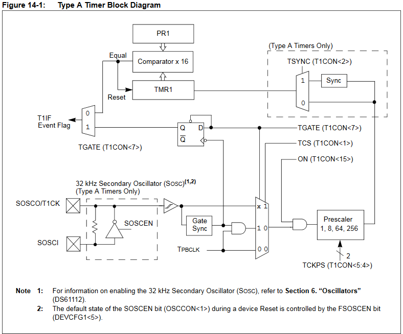
- Type A timer (timer 1)
Type A timer can be clocked from the PBCLK (peripherial bus clock), from an external pin, or from the secondary oscillator (see below). There is a period register,PR1, with hardware compare to the timer counter. Equality of the 16-bit counter TMR1 and PR1 resets the timer and may trigger a hardware event (DMA burst or interrupt). Typical initial setup would be to use the PBCLK source, choose the prescalar divider, and PR1 period value to set a timeout interval. The low speed secondary oscillator could be used with an external resonator to make an accurate real-time clock. The type A Timer can operate asynchronously from an external clock source. Using this clock source, the Type A Timer module can continue to operate during Sleep mode. To operate in Sleep mode, the Type A Timer module is configured as follows:
• Timer1 module is enabled, ON bit (T1CON<15>) = 1
• Timer1 clock source is selected as external, TCS bit (T1CON<1>) = 1
• TSYNC bit (T1CON<2>) is set to a logic ‘ 0 ’ (Asynchronous Counter mode enabled)
When these conditions are met, Timer1 continues to count and detect period matches when the device is in Sleep mode. When a match between the timer and the period register occurs, the T1IF status bit is set. If the T1IE bit is set, and its priority is greater than current CPU priority, the device wakes from Sleep or Idle mode and executes the Timer1 Interrupt Service Routine
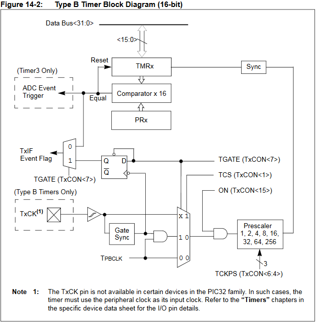
- Type B timer (timer 2 to 5)
Type b timers can be clocked from the PBCLK (peripherial bus clock) or from an external pin (see below).Type B timers may be
used individually as 16-bit timers, or grouped into timer23 and timer45 as 32-bit timers. Equality of the 16(32)-bit counter TMR and PR resets the timer and may trigger a hardware event ( DMA burst, interrupt, and/or ADC conversion). Typical initial setup would be to use the PBCLK source, choose the prescalar divider, and PR value to set a timeout interval. Type B timers stop operating in sleep or idle modes if they are running from the PBCLK.
- Type B Timer configuration:
PLIB contains functions to turn on/off timers, to , read/write the timer counter register, read/write the period register and set up interrupts.
- To open a timer: The following turns on the timer, sets the clock source to PBCLK,
sets the prescalar to one, and the period-register to timeout after 400 ticks of the clock.
OpenTimer2(T2_ON | T2_SOURCE_INT | T2_PS_1_1, 400);
- To open a 32-bit timer use something like
OpenTimer23(T2_ON | T2_PS_1_256 | T2_32BIT_MODE_ON, 0x00A00000);
- To configure an interrupt you need to choose a priority level and clear the flag.
There are also separate disable/enable commands to turn off/on an interrupt.
ConfigIntTimer2(T2_INT_ON | T2_INT_PRIOR_2);
mT2ClearIntFlag(); // and clear the interrupt flag
- To read a timer as an integer or short
currentValue = ReadTimer4();
- To write a timer
WriteTimer1(0x000); // zero the timer
- To write to the period register
WritePeriod1(1000);
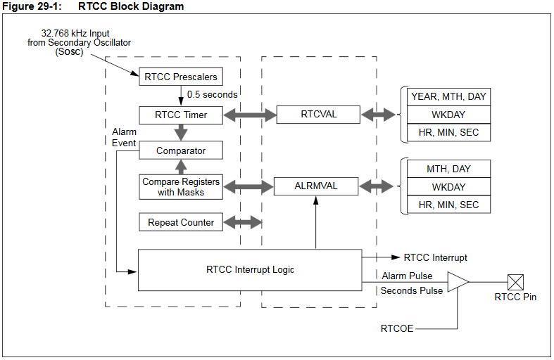
- Real-Time Clock and Calendar (RTCC)
The
RTCC requires an external precision oscillator at 32.768 kHz. (example). Some of the features are below.
This device is very handy if you need alarm clock type of functions. See also the RTCC page.
- Time in hours, minutes and seconds in 24-hour format (military time)
- Provides calendar for weekday, date, month and year
- Alarm configurable for one second, 10 seconds, one minute, 10 minutes, one hour, one day, one week, one month, one year
- Year range from 2000 to 2099
- Binary Coded Decimal (BCD) format for smaller firmware overhead
- Alarm pulse or seconds clock output on the RTCC pin
- Because the RTCC works in idle or sleep mode, a RTCC interrupt can wake up the cpu.
- Core Timer
The core timer has a count register which is incremented every two system clock (SYSCLK) cycles. There is a Compare register which is used to cause a timer interrupt if desired. An interrupt is generated when the Compare register matches the Count register. An interrupt is taken only if it is enabled in the Interrupt Controller module. Generally you will not use this timer in application code. It is used by the TFT library to generate short delays.
- Watchdog timer
The primary function of the Watchdog Timer (WDT) is to reset the processor in the event of a software malfunction or wake-up the processor in the event of a time-out while in Sleep mode. If enabled, the WDT will increment until it overflows or “times out”. A WDT time-out will force a device Reset, except during Sleep or Idle modes. The WDT module may be used to wake the device from Sleep mode or Idle mode. When the WDT times out in a Power-Saving mode, a Non-Maskable Interrupt (NMI) is generated and the WDTO bit (RCON<4>) is set. The NMI vectors execution to the CPU start-up address, but does not reset registers or peripherals. The WDT module uses the LPRC Oscillator for reliability. The LPRC Oscillator is separate from the FRC. It oscillates at a nominal frequency of 31.25 kHz (+/-15%).
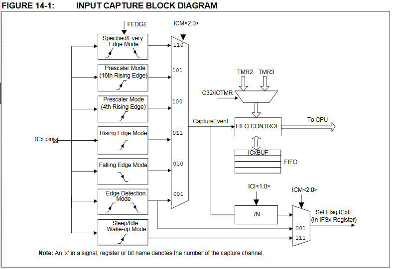
Input Capture Units
Timer 2 or 3 can be used as a time source for time capture based on an external event, such as a rising or falling edge on an ICx pin.. This allows very accurate (1-cycle) timing of events independent of software. Our cpu has five input capture units. All if the IC event-inputs are on PPS, and therefore may be moved between 8 different external pins. An example in An older lab uses one timer to drive two output compare units to produce two pulse trains, and a second timer to act a source for input capture of the period of either pulse train.
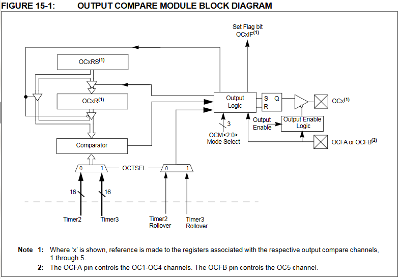
Output Compare Units
Timer 2 or 3 can be used as a time source for generating an external event, such as a rising or falling edge or PWM signal. This allows very accurate (1-cycle) generation of events independent of software. Our cpu has five output compare units. All if the OCx pulse-outputs are on PPS, and therefore may be moved between 8 different external pins. There is Hardware-based PWM Fault detection and automatic output disable (OCFA or OCFB inputs). An example in An older lab uses one timer to drive two output compare units to produce two pulse trains, and a second timer to act a source for input capture of the period of either pulse train.
Oscillators
The PIC32 oscillator system has the following modules and features:
• Four external and internal oscillator options as clock sources. Primary osc, secondary osc, fast RC osc, low power RC osc.
• On-chip Phase-Locked Loop (PLL) with a user-selectable input divider and multiplier, as well as an output divider, to boost operating frequency on some internal and external oscillator sources
• On-chip user-selectable divisor postscaler on some oscillator sources
Generally in this class, the oscillator will default to the fast RC, FRC, 8 MHz +/-0.9%, clock, as specified in the Protothreads config file.
See the full list of configuration-bit options for more information.
In the file there are three pragma lines:
#pragma config FNOSC = FRCPLL, POSCMOD = OFF
#pragma config FPLLIDIV = DIV_2, FPLLMUL = MUL_20, FPLLODIV = DIV_2 //40 MHz
#pragma config FPBDIV = DIV_1 // PB 40 MHz
--The first line sets the Oscillator Selection Bits (FNOSC) to use the Fast RC Osc with PLL. The PLL allows the system to multiply the 8 MHz FRC to a higher rate. It also disables the primary oscillator by setting POSCMOD off. See below for using the primary oscillator.
--The second line divides the FRC by two because the PLL input must be 4 MHz. Then it sets the PLL to multiply by 20 and divide by two to get 40 MHz cpu clock. Range is 15≤FPLLMUL≤24 and
1≤FPLLODIV≤256. But check the config page for details.
--The third line sets the peripherial bus speed to be the same as the cpu speed.
FPBDIV can be set to 1,2,4,8.
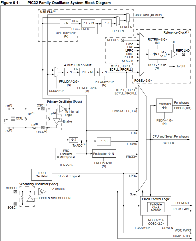
From the diagram below (figure 6-1), you can see that there are many ways of setting up the oscillator system to minimize power, or maximize performance, or run USB. To run the USB PLL you must use the primary oscillator with an external 12 MHz resonator!
Using an external primary oscillator
An external oscillator can be much more accurate than the internal RC oscillator (FRC oscillator). I tried a SiTime SIT2024AA -S8-33E-8.000000E 8 MHz MEMS oscillator connected to the OSC1 clock input. This pin is on i/o pin RA2. Adding the external clock disables RA2 for general i/o. The oscillator worked easily when connected to the SECABB v2 with port expander installed, but the clock signal did not pull down all the way to Vss because of the port expander.
This means that on the SECABB you cannot turn on the port expander interrupt INTB because it can affect clock integrity.
Solutions:
-- You could remove the port expander when using the external oscillator, but that is often not feasible.
--
If you do not need i/o expander interrupts, cut pins 19 and 20 (INTA and INTB) off the port expander IC (see datasheet).
--
The full work-around for the pin-use collision is to first turn on the interrupt mirror function on the port expander so that only one interrupt pin is necessary, then cut off port expander pin 19 which is attached to RA2. In the function initPE() you would modify the setting CLEAR_MIRROR to SET_MIRROR, then only detect an interrupt on RA3.
One line of the config_1_3_2.h file (see above and the full list of configuration-bit options) must be changed to:
#pragma config FNOSC = PRIPLL, POSCMOD = EC, OSCIOFNC = OFF
This pragma line:
--
Selects the precision primary oscillator in PLL mode.
-- Enables an external oscillator module input (not a crystal).
-- Turns off the optional function for port OSC2 (RA3), which is to output the peripherial bus clock (PBCLK).
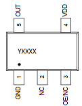
The SiTime oscillator is packaged in SOT23, which is a small, but easily soldered surface mount.
I put it on an Adafruit SOT23 breakout board. You need:
--
to wire a 0.1 uf bypass capacitor between Vdd and GND,
--
connect the OUT to RA2
--
wire the OE input to Vdd.
The oscillator SOT-23-5 package is shown below.
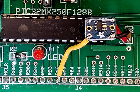
This small circuit has been added toto the PCB for SECABB v2.1. (Look just above the RA4 and RB5 pinouts).
But for testing, a small circuit board was hacked onto the SECABB v2. In the image below,
an existing capacitor (C1) on the board is used as the oscillator power connection and bypass capacitor. The
oscillator output was hard-wired to RA2. You may be able to discern that the SOT-23-5 pin 2 (middle-right side)
on the oscillator package was not soldered. That is because it is internally a no-connect. The left-middle pad
has a droplet of solder on it by mistake, but there is no pin there anyway.
For many applications, the internal oscillator ( fast RC, FRC, 8 MHz ±0.9%) is good enough, but for time keeping or for music synthesis, a 1% error is too high! For time keeping, you need better than 0.005% accuracy (4 seconds/day), and a cheap watch is at least 10 times that accurate! The MEMS oscillator is good to about 0.003%. For music, you need at least 0.2% accuracy. Comparing audio synthesis between the internal oscillator and the external MEMS oscillator for a nominal 440 Hz sine wave gives 441.36 Hz (0.3% error) for the internal oscillator and 440.04 (0.009% error) for the external MEMS oscillator. It turns out that the calculation for 44 KHz sample rate was rounded off from 909.1 cycles (40 MHz/44 KHz) to 909 because the timer compare-register can only be set to integer values. So the frequency measured should be about 0.01% high, which it was. The TDS1012 oscilloscope specfication gives an frequency measurement accuracy of 0.005%, so the MEMS oscillator is approximately as accurate as the scope can measure. Changing the sample rate to be an exact 1000 cycles results in 440.00±0.03 Hz variation in the scope measurement.
Copyright Cornell University
October 21, 2019