Introduction
Stewie: A 3DOF Motion Table
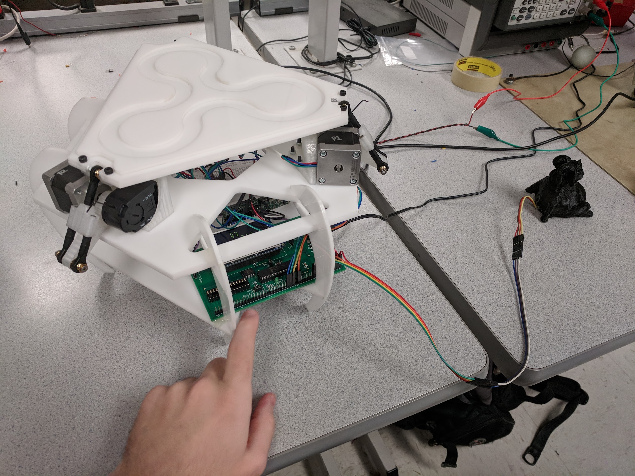
This website serves as irrefutable evidence that a single goat, with the help of a few stepper motors, really can move mountains. Team Micro-goat proved this hypothesis by building a Stewart motion platform controlled by an accelerometer embedded within the aforementioned goat. We have dubbed our diabolical creation Stewie. The platform mirrors the attitude of the goat to about one degree of accuracy, and is able to lift about five hundred grams of alfalfa, shrubbery, socks, and other goat foods. Stewie’s brain is a PIC32MX250 microcontroller. While much of his current utility is as a form of entertainment, we hope that Stewie can eventually fulfill many practical jobs, such as testing spacecraft sensor systems, calibrating antenna designs with extreme accuracy, and as a VR simulator motion platform for ferrets.
Close
High Level Design
Our rationale when picking a project was to design a physical device that involved significant electrical and mechanical integration, an interesting controls problem, and that would provide us with an interesting and useful piece of hardware when everything was over and done with.
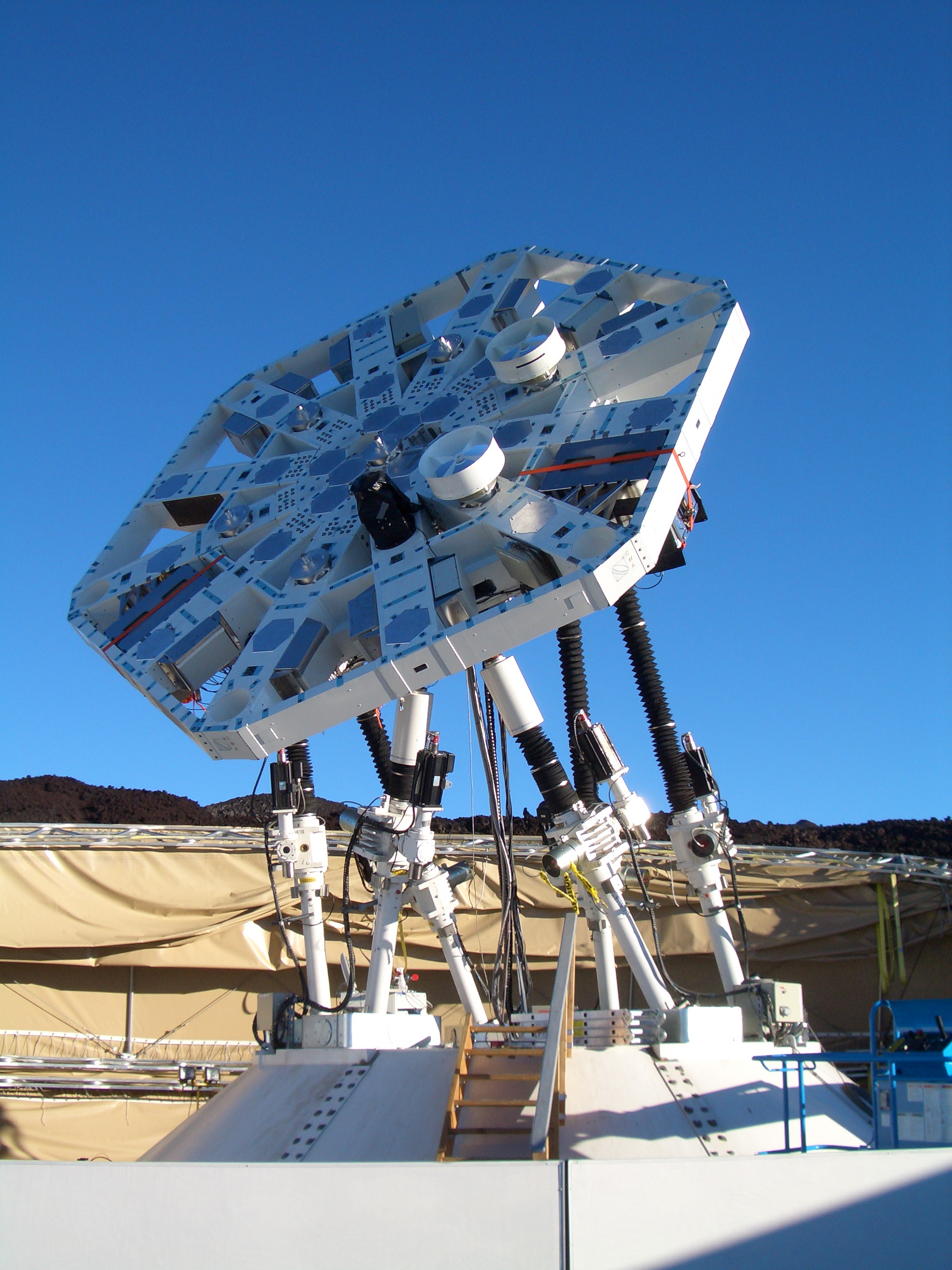
While our initial considerations were all flying devices, we decided to stay grounded in reality with a project that would be easier to test at the bench. We found a few youtube videos of stewart platforms, which are commonly used in a 6DOF configuration as the backbone of car and airplane simulators. Here’s a picture of a large stewart platform used to point experimental antennae.
We eventually came upon this 3DOF variant being used to roll a marble around on a plate.
This design served as the inspiration for our project’s mechanical design. Rather than running a closed loop control system on a marble with a capacitive touch screen, as shown in the above video, we decided to invite user input through an accelerometer embedded into a controller.
Our motion platform was designed with three degrees of mechanical freedom, while the accelerometer is only outputs two values for pitch and roll of the controller. These values are calculated by measuring the downwards acceleration of gravity. The Z (vertical) axis of our table is thus constrained to a constant value in software. While it’s true that we could have achieved 2DOF movement with only two actuators rather than three, we preferred the look of the triangular table and thought that the control algorithm needed to translate from accelerometer readings to motor outputs would be an interesting challenge.
Close
Hardware
The first step of the hardware design was to pick components and order them from the cheapest available source; our rationale for each choice, and component details, can be found below. In our case we used sourced using Ebay and Amazon.
Stepper Motor
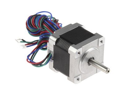
These stepper motors are small and powerful, measuring only 35mm in square base and outputting 18 Ncm of holding torque. These steppers have 1.8 degree steps, making a full rotation in 200 steps. These 4-wire bipolar stepper motors run off of 12 or 24V and pull a maximum of 1.6A.
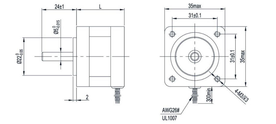
This diagram includes useful dimensions of the stepper motor, which we used to mount them to our project.
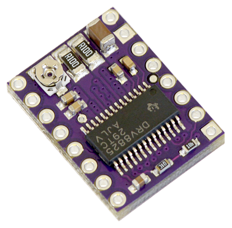
Stepper Motor Driver
We chose these stepper drivers because they have six micro-step resolutions, down to 1/32 of a step, meaning we can control the bipolar stepper motors with extreme precision. These drivers have adjustable current limiting, and can take in 8-45V.
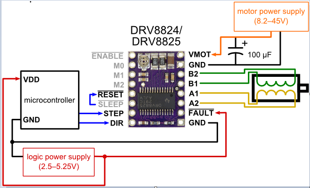
Stepper Motor Driver Wiring
We used the above wiring diagram to wire our Nema 14 stepper motors to the driver. In order to enable the 1/32 microstep mode, both the M0 and M2 pins were pulled high using 1KΩ resistors. The data sheet is here
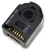
Avago Encoder
In order to implement a high accuracy closed-loop feedback system, we chose these optical encoders to track the absolute position of the stepper motors during movement. These optical encoders offer an extremely high resolution of 1024 counts per revolution. The encoders have floating shaft couplers for easy mounting to any shaft. These encoders are appropriately sized given our stepper size and can be easily packaged in alignment with the stepper shaft.
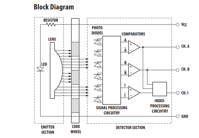
Avago Encoder wiring
Channels A,B, and I can be wired to digital inputs to trigger interrupt driven timers in order calculate the shaft position.
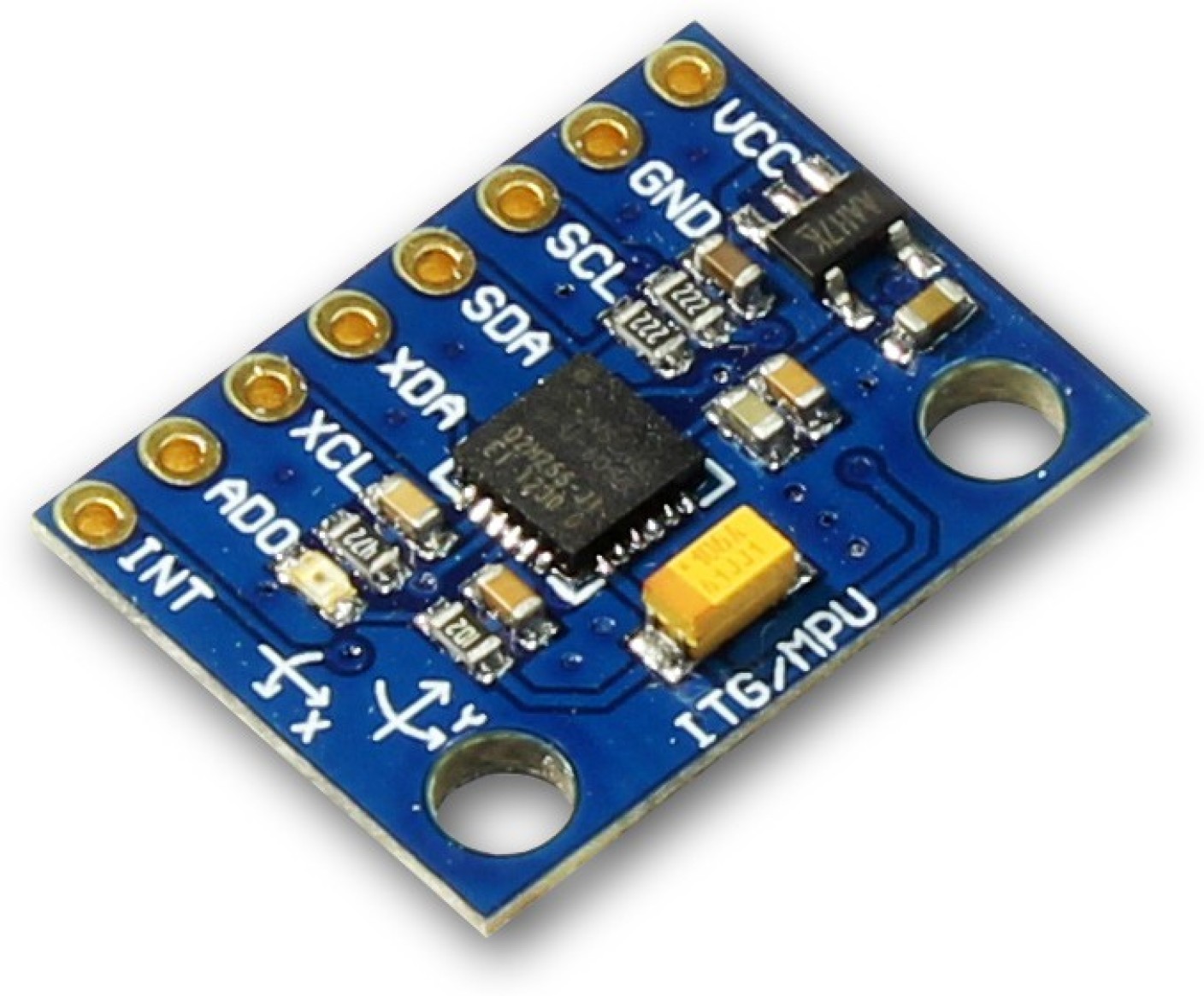
MPU6050
We chose this 6-axis accelerometer/gyro because it is commonly used in robotic applications and has lots of supporting documentation and examples. Additionally, the MPU6050 is capable or operating at 400kHz in fast mode via I2C. This high throughput of readings allows us to control the motion of the table with high sensitivity. For our purposes, we only used the accelerations readings in x, y and z axes, but not gyroscope readings. Because the readings are quite noise, we used a running average filter to smooth the data.
Mechanical Design
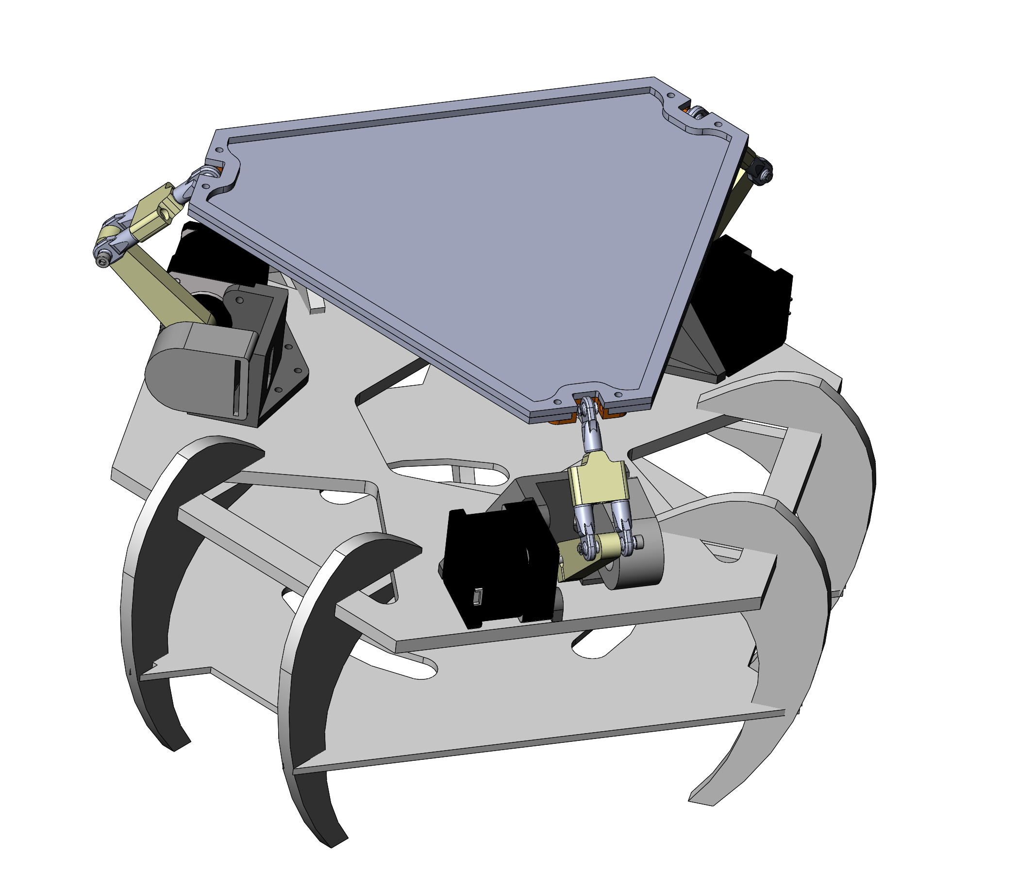
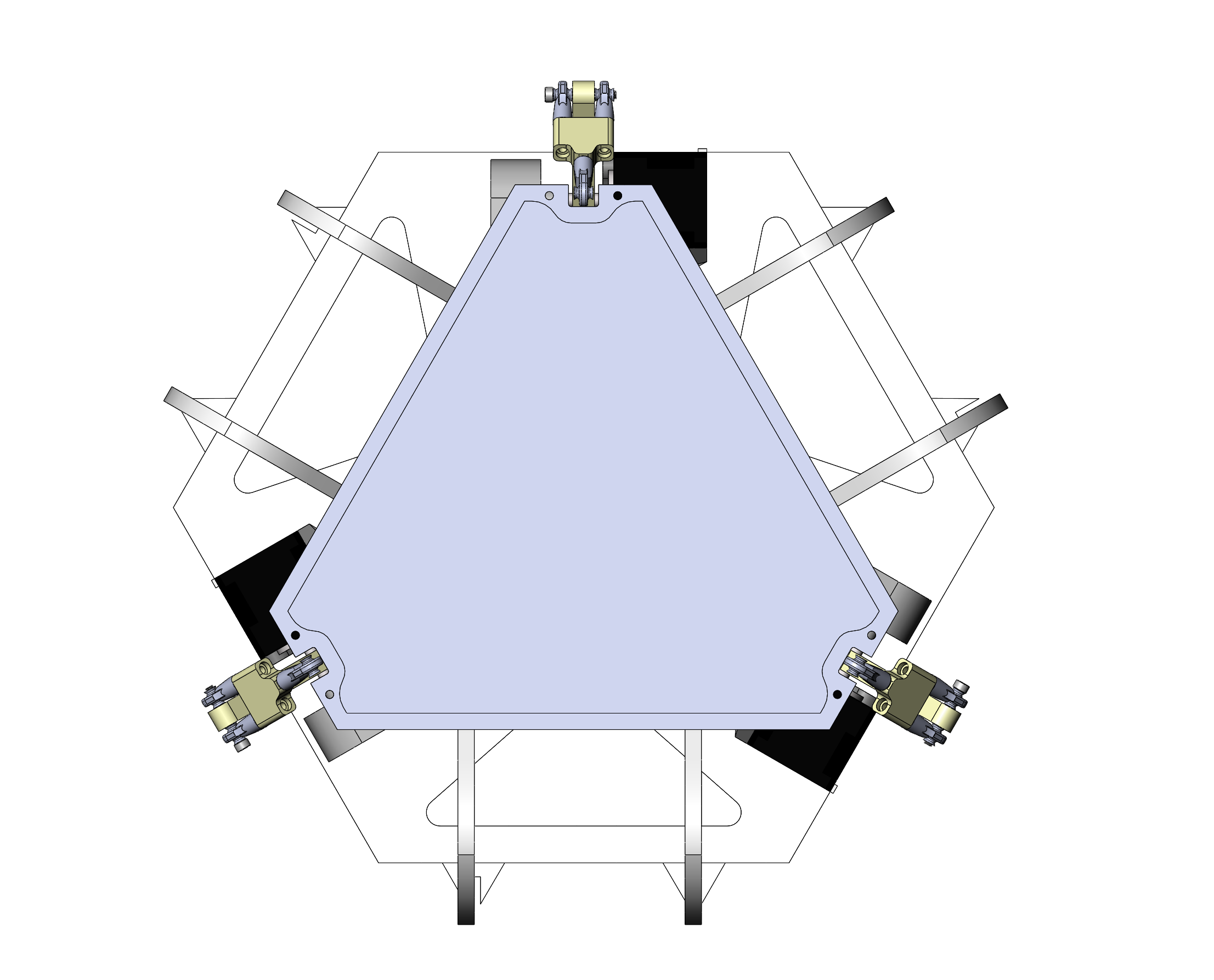
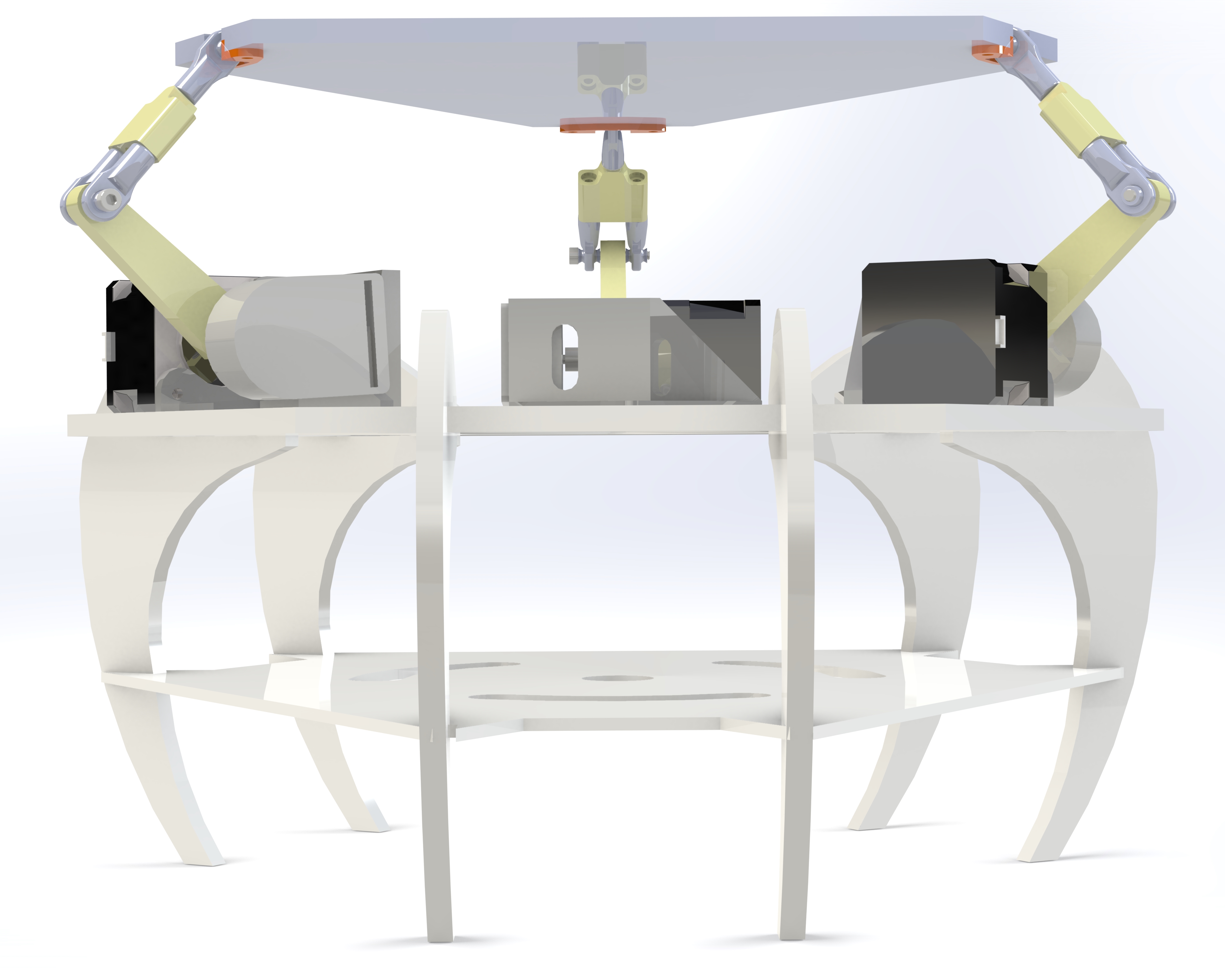
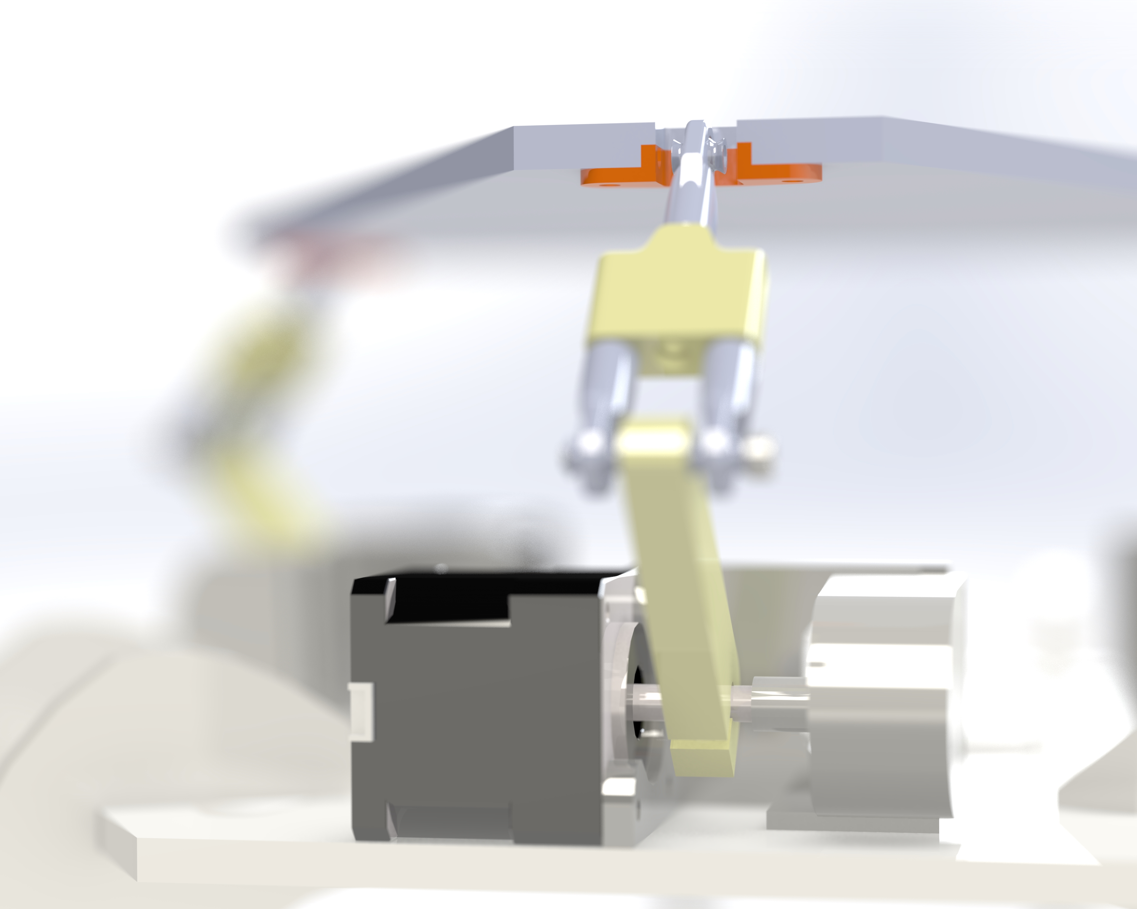
In order to allow for a fast iteration timeline on the hardware design, each part was carefully designed for rapid prototyping manufacture. In our case this means using only off the shelf hardware, 3D printed parts, and laser cut acrylic sheet. After arbitrarily picking the major dimensions of the table and base, we split the hardware design into two projects for faster execution. Adam modeled the ball joints, designed the two-piece arms using a “Y” configuration to stop unwanted rotation, the attachment method to the table and stepper motor shafts, and designed the acrylic table itself. Eric modeled the stepper motors and encoders, 3D printed mounts to hold these components together, and an acrylic base for the entire project and some beautiful arachnid inspired legs. Most of the parts required an iteration or two to find the perfect design and fitment, but we were prepared for this eventuality and finished the hardware design a few weeks before the deadline for the integrated project. The finished CAD design can be seen below in all its glory:
In the spirit of our team mascot, the μgoat, we 3D printed a micro-goat to serve as the user controller for our stewart table. This goat was carefully sized to be ergonomic and ayn user’s hand. The MPU 60-50 was embedded into the base of the goat, with long extension wires connecting to the main PIC32 board. As the controller is manipulated by the user, the stewart table mimics the tilt and motion of the micro-goat.
Close
Software
The software for this project is split up into a couple categories: sensor reading, the dynamics/control algorithm, and motor driving. It can be found here. The main file that our code runs from is called stewie_main.c. Additionally, we used the protothreads, tft display, and I2C helper libraries.
Accelerometer Reading
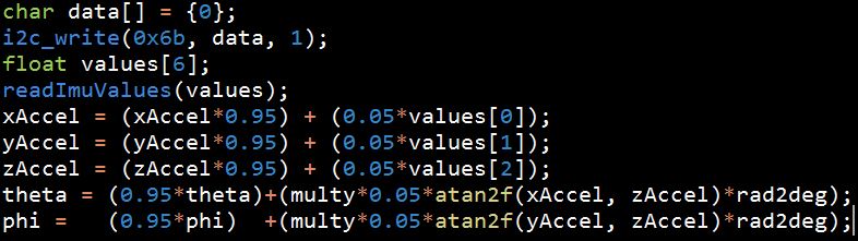
Reading from the Invensense MPU6050 module is quite simple as the data sheet spells out the register map quite well. Additionally, it is an incredibly popular device with a plethora of different libraries written for it. In our case, we decided to abstract complexity and used the i2c_helper.h library written by Caulley, Nehoran, and Zhao in their 2015 4760 final project. Using their helper functions this is the general form:
Code Snippet
The readImuValues function packages the three accelerometer and three gyroscope values into a single array named values[]. Then to read the values, the index of the value of interest is called. Because the IMU values were somewhat noisy and very sensitive to movement, we implemented a running average smoothing filter using a 20th time step average. Then, using the x, y and z acceleration values, weable to calculate theta and phi, describing the orientation of the table in the X and Y axes. These two angles are the inputs to Padraig’s algorithm which outputs the stepper movements for each stepper motor in order to set the table to the orientation determined by theta and phi.
Dynamics and Controls
Platform Coordinate and Vector Definitions
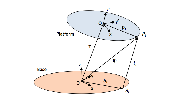
This photo illustrates the coordinate systems that are used in this project. We base everything around the body frame where the constant T vector describes the length and direction from the origin to the center of the table. Technically, given that this system as theta, phi, and z degrees of freedom, this T vector could be a dynamic input. For the purpose of simplicity we initialize this vector as static for now. This is to say that the center of the moving platform should remain stationary. The B-sub-i vector describes the constant vector from the origin to the actuator shaft. The L-sub-i vector describes what must be calculated which is the length that needs to be output from the system. The motor spins two 3D printed segments which move upwards. We will calculate this in the next step. The P-sub-i vector describes the constant vector from the platform frame origin to the end-effector pivot point. We can see that, once we have rotated the p vector into the body frame, we can easily calculate the L-sub-i vector by a summation of the other vectors. This is shown in equation one below. I will also describe the direction cosine matrices. The sub-i values represent each of the actuators and therefore the calculations for for arbitrarily many effectors.
Vector Math
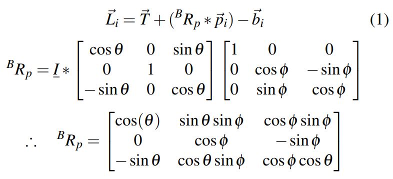
Equation one above shows the sum of vectors that allow us to calculate the shaft-to-platform vector for each of the three motors. The matrix called BRp below equation one shows the theta-phi restricted direction cosine matrix. This matrix allows us to transform vectors in the platform frame to ones in the body frame. This is useful for calculating the sum of vectors in the body frame. For a given input theta and phi, which are taken from the accelerometer readings, the p-sub-i vector values will change in the body frame and this matrix is required to find those. The identity matrix shows that we zeroed out the psi direction cosine matrix.
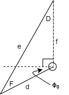
Actuator Schematic
The figure above shows the shaft of the motor (the circle) and the legs that attach it to the platform and allow it to move. The capital letters denote angles, where the lowercase denotes length of the side of the triangle. Large E, opposite of side e, is the sum of this rest angle, 90 degrees, and the negative of the shaft input angle. The dotted line ‘f’ value is the Euclidean norm of the L vector that we have calculated and is an input to this calculation (we have already determined it using equation one and our angle inputs). Phi-sub-zero denotes the natural state of the leg, which is resting against the body. This is a constant value.
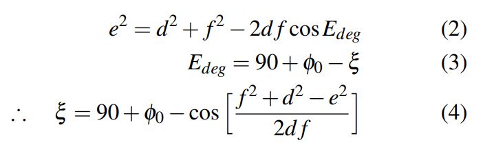
Actuator Math
The equations above show how we will find angle that must be sent to the motors. E is calculated by using equation two: the law of cosines. We know that the angle E is the summation of the rest angle phi-sub-zero, 90 degrees, and our shaft input angle. Therefore, we use equation four to find our xi value which is the angle that the shaft of the motor needs to turn. This angle in degrees is converted to step values and sent to the motor driving code.
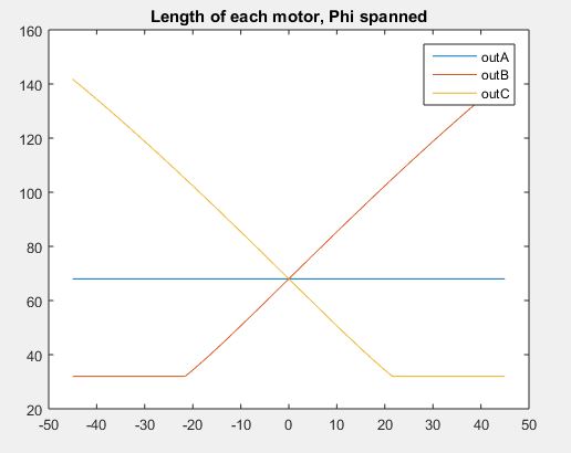
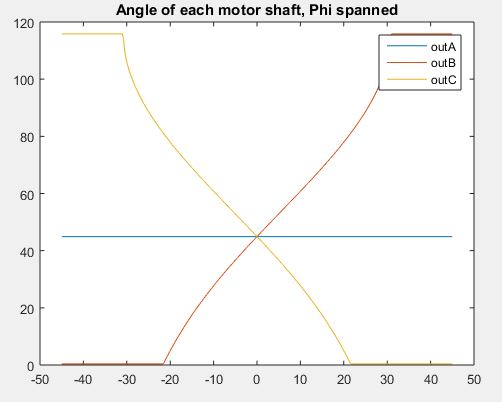
Before we implemented this algorithm, we wrote it in MATLAB to confirm that all numbers made sense. This especially helped when our calculations yielded complex values which would otherwise shut down the PIC processor.
Motor Driving
Another aspect of the design that was important for smooth operation was the stepper motor drive design. Our motors have 200 discrete steps per full 360 degree revolution, resulting in a precision of 1.8 degrees per step. This isn’t particularly high; luckily the motor drivers we chose, the Texas Instruments DRV8825, includes a functionality called microstepping wherein the motor can achieve sub step accuracy. We ran our motors at the maximum micro step quantity of 32, which is set using a simple resistor pull-up selection. This results in motors that now take 1600 steps per full revolution with a theoretical precision of about .05 degrees.
The motor drivers are controlled by the microcontroller through an interface of two digital pins per driver. The DIRECTION pin sets the direction of rotation, and a pulse to the STEP pin steps the motor once in that direction. This code must be run in a high frequency, timer controlled ISR to achieve reasonable output speeds in the 32 microstep mode. The maximum speed of the motors is set by the frequency of this ISR; the difficulty of driving the motors smoothly is that in the simplest implementation of the microcontroller ISR the motors will always run at full speed towards the target position. If the ISR is setup with a high period, the motors run smoothly but the maximum speed is limited. If the ISR is setup with a low period, the motor can run extremely fast but is likely to accelerate quickly to each target position and then brake suddenly on arrival causing a noisy, jittery performance.
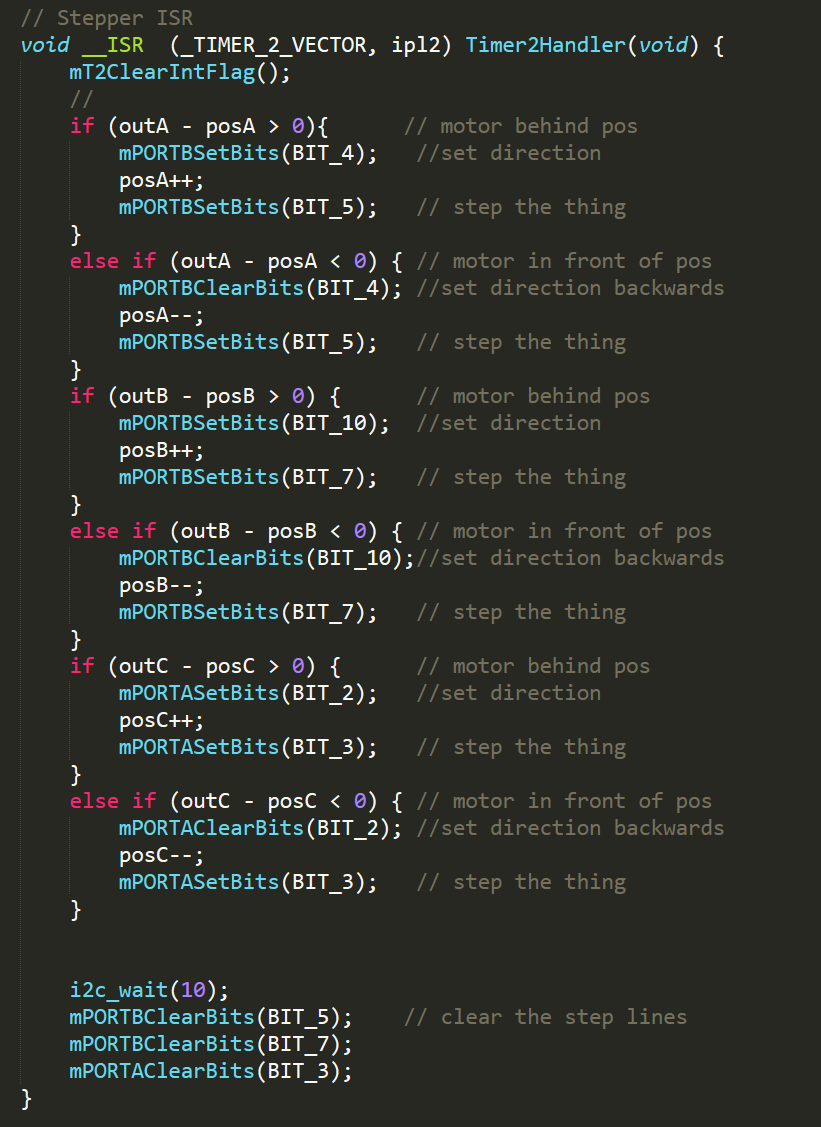
Our initial implementation of stepper driver code simply determined the direction of movement between each motor’s current position and its target position, and stepped the motor once in that direction. Here is what our ISR function looks like:
We also spent a while working on a more optimal method of driving the stepper motors with variable speed. The theory here was that rather than having the IMU thread update the target position, and the ISR step towards that position at maximum speed, the IMU thread would also calculate and set a speed of rotation for the ISR to carry out. This is implemented with the variable stepInterval, generated by function computeNewSpeed(), which is used in the ISR loop to skip steps for smooth changes in motor speed. If stepInterval is set to 1, the motor will run at full speed. With a value of 2 it runs at half speed, at three one third speed, et cetera. Here is the implementation:
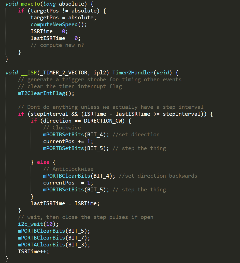
The result of this change is that the ISR can be run at an extremely fast frequency, setting the maximum speed of the stepper motors higher without sacrificing smoothness. The above implementation was tested with a single stepper motor successfully, but we did not have time to get all three motors running using this variable speed system and thus demoed with the initial stepper driver method.
Close
Results & Future Improvement
Testing Accelerometer
After using the I2C helper library created by other 4760 students, we were easily able to read IMU data from the MPU 6050. We wrote a simple thread to print out the xAccel, y Accel, and zAccel values to the TFT screen. Then we manipulated the accelerometer to ensure the readings were as expected. The readings were appropriate to given changes in orientation, but when held still, the values were far from static. The values stayed relatively constant, but they still jumped up and down quite frequently when the accelerometer was not moving. When it came time to test the transformation algorithm, the table was extremely jittery due to the noise in the IMU. To improve this we implemented a simple running average filter to smooth the incoming readings. This improved the vibration of the table when the IMU was being held still. We changed the smoothing timestep until the table stayed fixed when the IMU was fixed. The final filter implemented was a 20 step filter, meaning every 20th reading is average with the previous 19 readings.
Testing Stepper motors
Because we built the stewart platform very early on with stepper motors installed, we setup an additional testing station with a stepper and stepper driver to test stepper movement without the physical constraints of the table, which limit range of motion. Two main issues arose when trying to control steppers, speed control and smoothness of motion. In order to achieve high resolution stepping, we chose to run the motors at 1/32 microsteps, meaning every microstep is 0.05 degrees of rotation. By running at 32 microsteps we achieved very smooth control, but the movement was very slow. Because the stepper movements are updated in the ISR, the ISR frequency determines the velocity of the stepper rotation. By decreasing the ISR timer period, which in turn increases the ISR frequency, we were able to achieve both smooth and fast movement. These results were determined form independent stepper testing separate from the stewart table. We also used this setup to implement minimum and maximum stepper positions by setting bounds on the variables that track stepper position. Then we tested setting setpoint for the stepper and ensuring the stepper would always reach the setpoint quickly and smoothly. Another important factor we tuned in this setup was current limits for the stepper drivers. Unless the current limits were set properly, the motor could skip steps or vibrate unnecessarily. We set the current limits relatively low to keep the vibrations low while still having enough current to provide sufficient torque. This current was approximately 0.1-0.2A per stepper motor.
Algorithm Testing
Once we achieved smooth and quick setpoint tracking on a single motor with hardcoded setpoints, we implemented Padraig’s algorithm to convert accelerometer readings to stepper setpoints. When we first tested this, the motor was behaving quite spontaneously. It would generally change setpoint as the accelerometer change orientation, but it was not always correct. After troubleshooting and reverting back to the Matlab calculations done to establish the algorithm, we noticed that complex values were being generated in the conversion from the equations converting the length vector to the stepper angle. By setting the bounds to the input of the arccosine function we resolved this issue and the stepper began behaving appropriately.
Full Platform Testing
After the algorithm correctly converted accelerometer data to stepper motion on a single stepper outside the stewart platform, we tested the each of the algorithm’s stepper angle outputs by switching the stepper motor to the three different drivers and ensuring the stepper shaft reacted appropriately. Once this was done, we moved to testing on the platform using all three motors. Fortunately, and somewhat miraculously, after performing all the previously described subsystem tests, the first full system test worked as expected as shown in the video below:
Calibration and Tuning
Of course, the table was quite jittery and loud, and there was still lots to be improved. For calibration, we ignore the IMU readings for the first few seconds to raise the table to the correct height, then IMU readings are accepted and passed through Padraig’s algorithm.To tune the system we played with two values, IMU_read_period, and TIMER2_peirod, which control the ISR and IMU thread frequencies respectively. After playing around with different values, we were able to analyze patterns of movement as we increased or decreased the value. As mentioned in the Stepper Motor section, By increasing the ISR frequency, we could achieve faster motion and therefore faster response time, but the stepper vibrations were augmented. By increasing the IMU frequency we also increased response time of the system with respect to user input, but again vibration increased due to high sensitivity to IMU changes. For best performance we spent a long time tuning the ISR period, and IMU read period, to work well with one another and to balance maximum performance with jitter reduction.
In the end we settled on an IMU read frequency of 500 Hz and an ISR frequency of 40KHz. This provided solid performance and speed. These were determined by increasing the ISR frequency until we had a fast speed without too much vibration caused by extreme accelerations.
Full System Results
All in all, we were very pleased with the performance of our stewart platform. We tested platforms ability to mimic acceleration orientation and movement by isolating certain axes. When the micro-goat was pitched forward or backward in the x-axis, only one motor would change angle because only the phi angle was changing. Then when the goat was tilted in the y-axis, the other two motors would change angel while the x-axis motor remained fixed because only the theta angle was changing. All of these results were observed and were in alignment with the expectations. Finally, in order to not exceed the mechanical bounds of motion of the platform, we tested our software-set bounds by tilting the accelerometer past the achievable range of the table to make sure the steppers did not try to achieve that angle. As expected, the motors would only go to their minimum or maximum position instead of forcibly trying to work against the systems physical constraints. To test the functionality and control of the platform, our first test was to balance a ping pong ball on the table. This video shows that our platform’s performance is controllable enough to be capable of balancing a ball given user input:
Our next test involved implementing a maze game which require the user to traverse a ball around a curved path by tilting the table without letting the ball fall of the table. Again our system was well tuned and was very capable of this test given good controller input. A video of a user playing the maze game is shown below:
Close
Conclusion
While some of the elements of our design could and will be further improved in the future, we’re very happy with how our results stand up to our goals and expectations. We had a lot of fun designing and building the hardware sections of the project, spent our fair share of time scratching our heads figuring out the software, and managed to get everything working in time for demo in the end. We also succeeded in creating a complete, aesthetically pleasing package for the project with a tray for electronics placement and legs to lift everything off of the table.
We were very grateful to be able to reference the i2c setup h file from the 2015 project Self-balancing robot - this saved us a lot of time getting the MPU working. The final performance of the motion platform after tuning was favorable. It swiftly updates to changes in the accelerometer input, with minimal noise at steady state.
We learned a lot from the process, and would definitely make some changes if we wanted to build a Stewie 2.0. On the input side, we would use more sophisticated filtering on the accelerometer to reduce jitter. Finishing off the variable-velocity stepper driver code would result in a great improvement of speed and smoothness; we will probably get this change implemented as soon as we’re back from break with our current hardware. We would also like to get the optical encoders running for closed loop performance and to eliminate drift from skipped steps over a long period of operation.
During the design and construction of Stewie, we strictly followed the IEEE Code of Ethics. We made safety conscious decisions such that nobody was in danger of getting injured. We were honest and realistic in stating our claims according to data collected. We were accurate in listing our component costs to our best knowledge. We strove to solve challenging problems by ourselves, sought the help of the instructor and TAs for those we were not able to resolve, and were willing to accept constructive feedback and incorporate it into our design. We did not hold any bias against anyone nor engaged in acts of discrimination based on race, religion, gender, disability, age, national origin, sexual orientation, and gender identity. We treated all of our peers with equal respect and offered help to our colleagues whenever possible. We gave credit when using code from any external sources, to prevent the perception of any conflict of interest, and acknowledge all contributions made to the final project.
Close
Appendix A
The group approves this report for inclusion on the course website. This group approves the video for inclusion on the course YouTube channel.
Appendix B: Commented Code
stewie_main.c
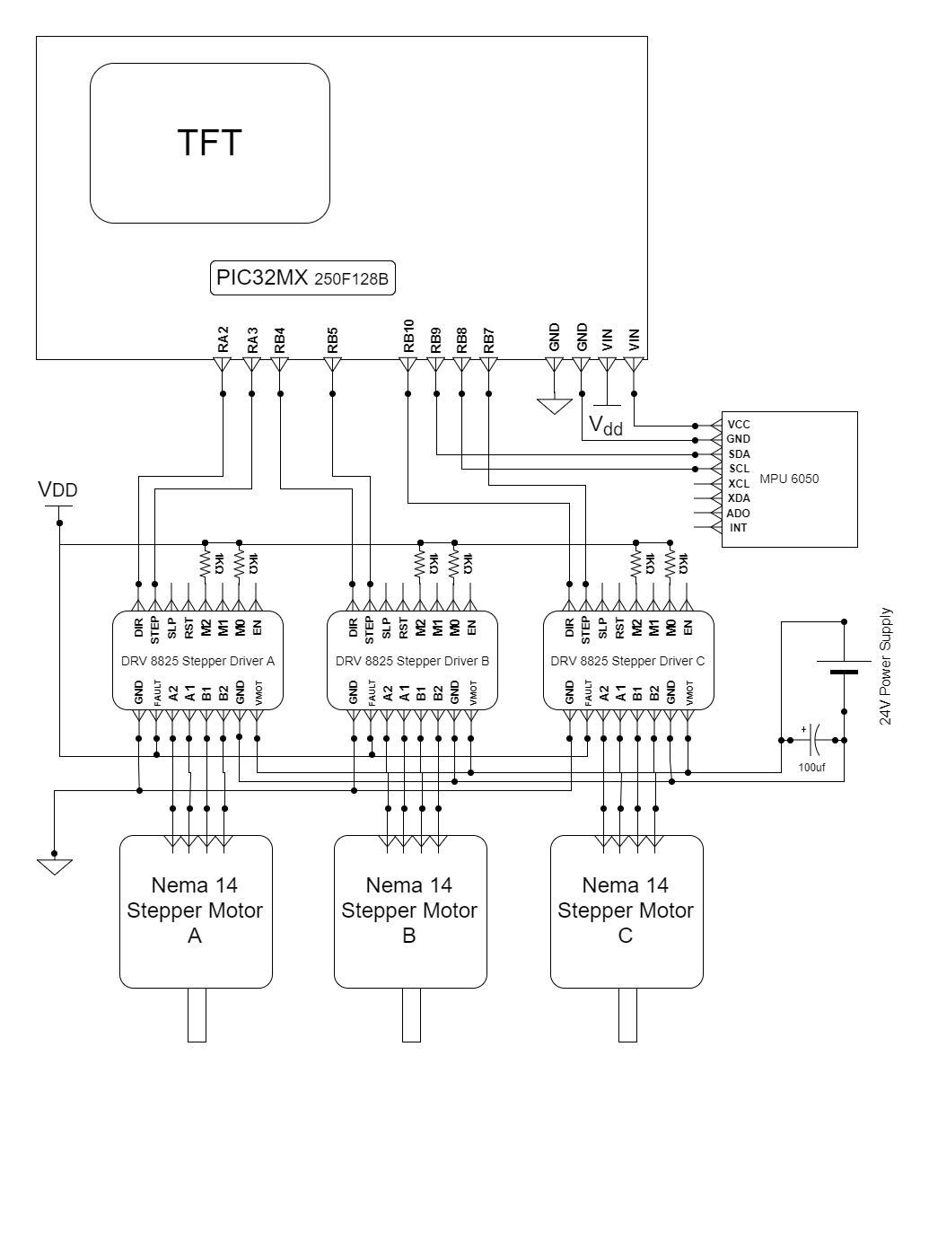
Appendix C: Schematic
Appendix D: Bill of Materials
Appendix E: Work Load Breakdown
- Padraig Lysandrou: Dynamics/Algorithm Software, Electrical Hardware
- Adam Weld: Table Design, Motor Driving Software
- Eric Berg: Platform Design, Electrical Hardware
Appendix F: References
- Inspiration from Instructables,
Posted Jan. 20, 2015
-
Wokingham U3A Math Group Paper on Dynamics of Stewart Platform
- Stewart Platform math
- Kinematic Calibration
of precise 6-DOF stewart platform. Juan Carlos JáUREGUI, Eusebio E. HERNáNDEZ, Marco CECCARELLI, Carlos LóPEZ-CAJúN, Alejandro GARCíA
Frontiers of Mech Eng, vol 8 2013.
-
Wheelchair stabilization by the control of a spatial 3-RRS mechanism,
Mehrdad Javadi; Narges Afzalpour; Peymaan Jafari; Mahdi KhorsandiJou
Article 5, Volume 17, Issue 2 -
Issue Serial Number 27, Summer and Autumn 2016, Page 84-100
- Stewart, D. (1965–1966). "A Platform with Six Degrees of Freedom".
Proc. Institution of Mechanical Engineers (UK). 180
- A Stewart platform-based manipulator: general theory and practical construction
EF Fichter - The International Journal of Robotics Research, 1986 -
The International Journal of Robotics Research
journals.sagepub.com
Contact Information
Padraig Lysandrou: PSL58@cornell.com
Adam Weld: AW698@cornell.edu
Eric Berg: EB645@cornell.edu
Close