Introduction
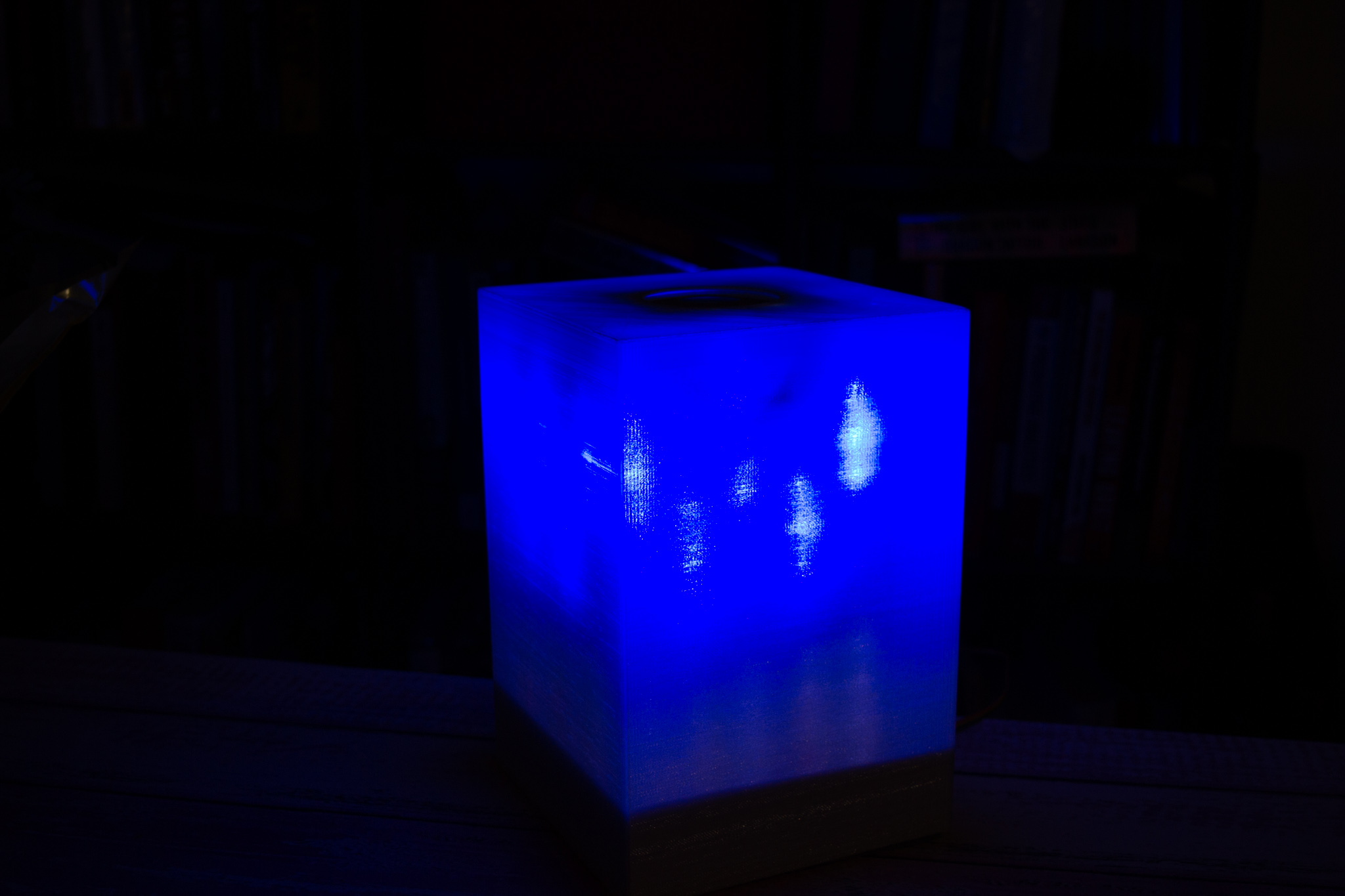
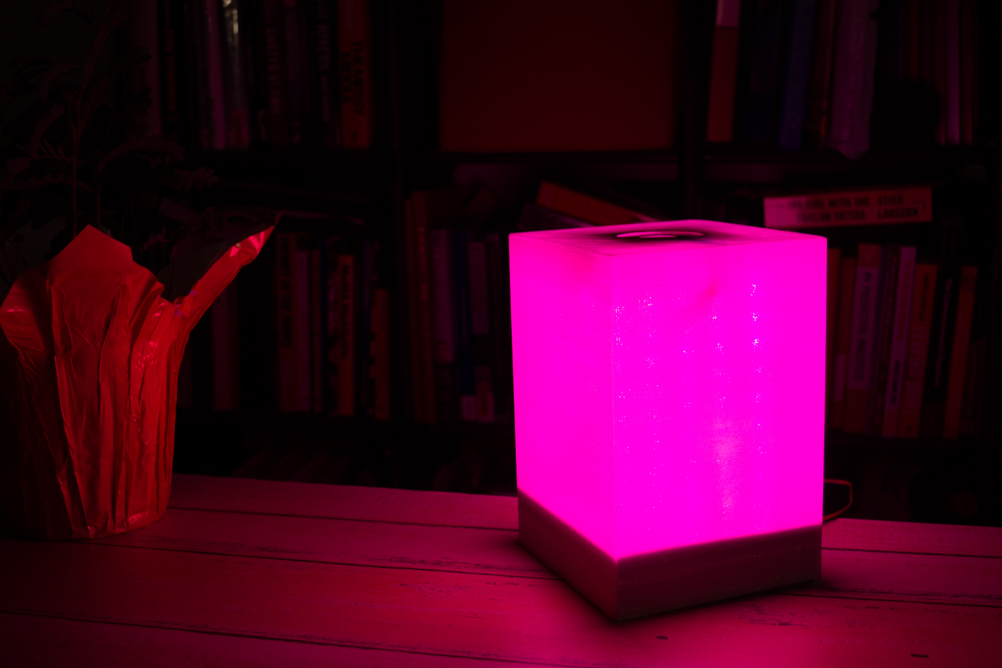
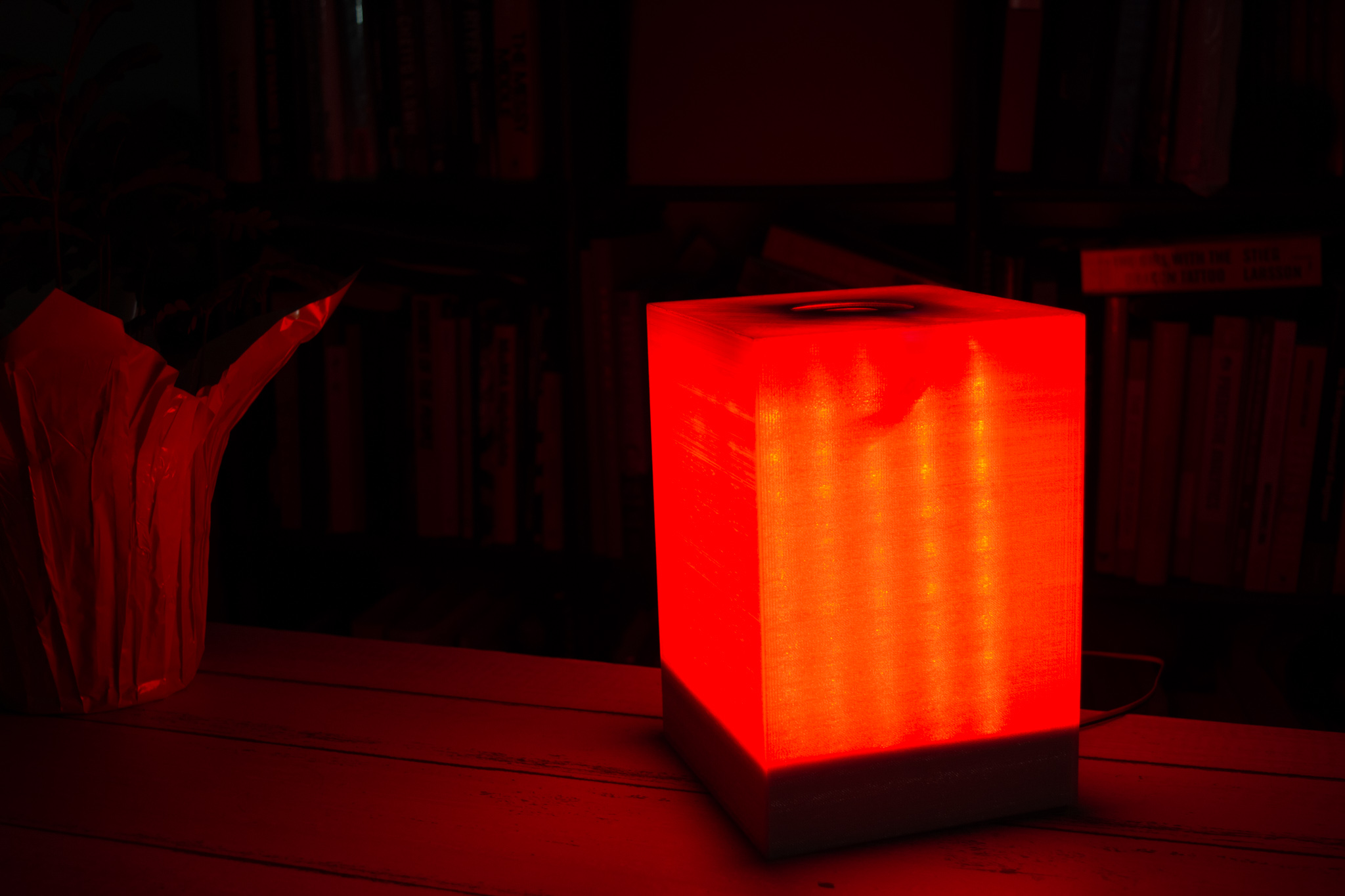
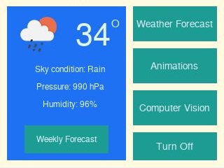
DOLORS is a smart lamp that, paired with a Raspberry Pi, is capable of showing live weather information upon request, such as the temperature and sky condition. Additionally, it provides dynamic animation modes with vibrant colors and computer vision features.
The main reason for building the SmartCube DOLORS was to have an easily accessible source of weather information on top of your desk, as well as the common features of a desk lamp and night light. DOLORS is able to display temperature and animations based on the weather conditions, become a desk lamp by illuminating a plethora of hues and be used as night light by displaying calming animations with color preferences.
The SmartCube was built combining the strengths of the Raspberry Pi and the PIC32. The PIC32 was used to drive all Real-Time intensive tasks. These tasks include reading input from sensors and driving 200 individually addressable RGB LED lights, in addition to a display with the current time and temperature. The Raspberry Pi was used mainly for its user interface design tools, its connectivity capabilities, and its processing power. It runs a multi-layered Graphical User Interface designed with Pygame, which allows the user to see live weather information, communicate commands to PIC32 via Bluetooth Low Energy (BLE), and detect shapes and colors to display on the lamp.
The scope of the content of this website limits to the work done using the PIC32 small board. For more information about design aspects controlled by the Raspberry Pi, visit this page.
High Level Design
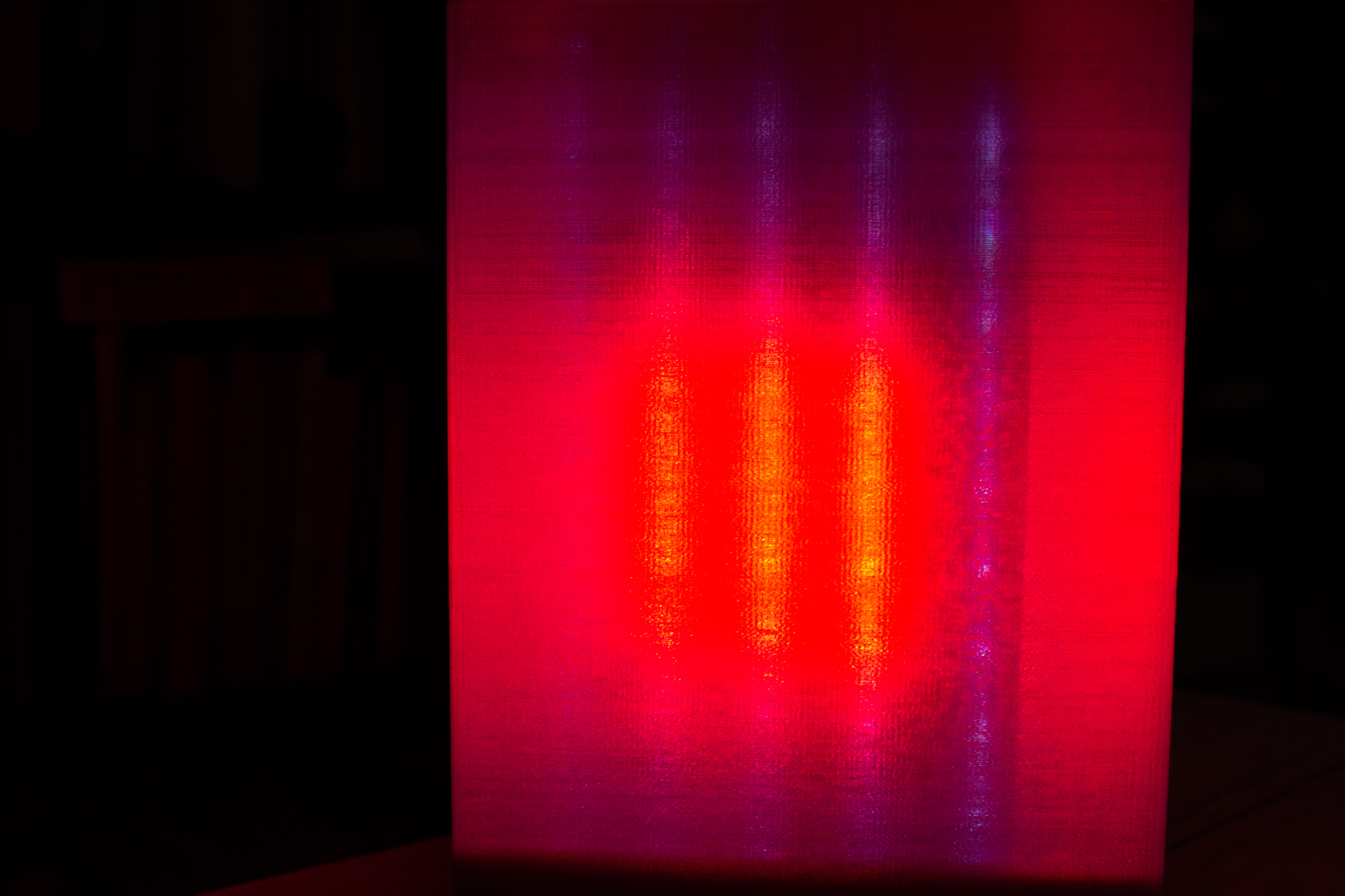
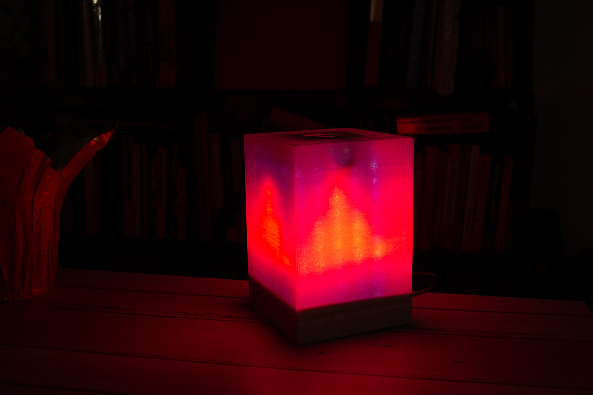
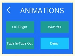
DOLORS is a smart lamp with a custom-built 3D-printed enclosure. It is capable of receiving commands and information from a Raspberry Pi via BLE. Depending on that information, it navigates several functioning modes, providing the user with live weather information, 3 lighting animation modes and computer-vision based shape and color detection.
Raspberry Pi
The Raspberry Pi uses a custom-designed GUI (built for ECE 5725 final project), which performs the following tasks:
- Download live weather information from the internet using OpenWeatherMap API.
- Download accurate time/date from the internet using python’s “time” and “datetime” libraries.
- Drives necessary software (OpenCV) and hardware (piCam) to implement color and shape detection.
- Uses onboard bluetooth module to communicate the previous information to an HM-10 BLE module connected to the PIC32.
For more details about the GUI and implementation on the Pi refer to the pictures in the Gallery, or visit this page.
PIC32 System

There are two input interfaces: a bluetooth module and a soft potentiometer. The PIC32 receives instructions from the Raspberry Pi via a HM-10 BLE module, which is connected to the auxiliary UART port. Once these instructions are decoded, the output interfaces respond appropriately. The soft potentiometer is used to change the color of the LEDs when the lamp is in the Fullbright, Waterfall and Color Fade animation modes.
Output interfacesThere are two output interfaces: a TFT display and an individually addressable RGB LED strip. When the lamp is first connected, it flashes “12:00” in the display, until the Pi sends the “Turn On” instruction, which updates it to the current time downloaded from the internet. Additionally, when the Pi sends the instruction to display “Weather Mode”, the current temperature outside is displayed in the TFT.

There are 200 LEDs distributed equally in 5x10 matrices among the sides of the cube. All four sides are connected to display the same animation. These are capable of displaying several animations based on the command received from the Pi:
Software Design
Schedule and Program Hierarchy
To schedule the different threads in our program we took a round robin scheduling approach in order to make sure all threads are run within a finite amount of time. Since we know that using round robin gives us the peace of mind that all threads will be run we decided to provide priority to threads based on their importance to how we wanted the system to operate. We set the thread protothread_timer to have the highest priority, this thread contains the all the conditions under which the leds will light up and construct animations, this thread needed highest priority in order to ensure that the leds worked correctly (the use of this leds requires high precision timing when sending bit streams). The thread with the second highest priority was then put on protothread_demo, this thread handles the demo mode and also needs high priority with respect to other threads because of its close contact with led setup and usage. The thread protothread_pot and long lost protothread_mic, 2 (rip), have third highest priority due to the need to make precise adc readings while in use, but have lower priority because these readings although precise do not happen often or as fast compared to the cpu clock since they are user dependent and the reaction time of the user is much lower than that of the cpu. Finally with lowest priority there are threads protothread_bluetooth and protothread_clock, the bluetooth thread handles information sent from the raspberry pi to set mode, time and weather; the reading execution can be low priority since the setting are set once and changed with very large times between them, running this thread once gives us all at once weather information, current time, and mode. The bluetooth thread does not have any time-critical task and running it with low priority allows us to no waste too much time that needs to be used in the threads with higher priority. The thread protothread_clock also has the lowest priority, this thread sends the time needed to be displayed on the TFT display and the only time sensitive aspect is running once every second and this time is very large compared to the cpu computations which means the thread will always execute in time.
pt_add(protothread_timer, 0);
pt_add(protothread_pot, 2);
// pt_add(protothread_mic, 2);
pt_add(protothread_demo,1);
pt_add(protothread_bluetooth, 3);
pt_add(protothread_clock, 3);
// === initalize the scheduler ====================
PT_INIT(&pt_sched);
// >>> CHOOSE the scheduler method: <<<
// (1)
// SCHED_ROUND_ROBIN just cycles thru all defined threads
//pt_sched_method = SCHED_ROUND_ROBIN ;
// (2)
// SCHED_RATE executes some threads more often then others
// -- rate=0 fastest, rate=1 half, rate=2 quarter, rate=3 eighth, rate=4 sixteenth,
// -- rate=5 or greater DISABLE thread!
pt_sched_method = SCHED_ROUND_ROBIN ;
// === scheduler thread =======================
// scheduler never exits
PT_SCHEDULE(protothread_sched(&pt_sched));
Configuration (setups)
Configure ADC channel for reading the potentiometer. This setup was put inside the function adc_setup(). The configuration steps can be seen in the steps below.
CloseADC10(); // ensure the ADC is off before setting the configuration
#define PARAM1 ADC_FORMAT_INTG16 | ADC_CLK_AUTO | ADC_AUTO_SAMPLING_OFF //
#define PARAM2 ADC_VREF_AVDD_AVSS | ADC_OFFSET_CAL_DISABLE | ADC_SCAN_OFF | ADC_SAMPLES_PER_INT_1 | ADC_ALT_BUF_OFF | ADC_ALT_INPUT_OFF
#define PARAM3 ADC_CONV_CLK_PB | ADC_SAMPLE_TIME_5 | ADC_CONV_CLK_Tcy2 //ADC_SAMPLE_TIME_15| ADC_CONV_CLK_Tcy2
#define PARAM4 ENABLE_AN5_ANA // pin RB3 (pot)
#define PARAM5 SKIP_SCAN_ALL
/* ======== Configure ADC to sample AN5 ========= */
SetChanADC10( ADC_CH0_NEG_SAMPLEA_NVREF | ADC_CH0_POS_SAMPLEA_AN5); // configure to sample AN5
OpenADC10( PARAM1, PARAM2, PARAM3, PARAM4, PARAM5 ); // configure ADC using the parameters defined above
EnableADC10(); // Enable the ADC
Threads
LED matrix controlTo control the LED matrix we used as starting point the sample code posted here. This sample code contains four functions that we modified to control the LED matrix according to our project needs. The execution of these four functions was initialized by the timer thread. The four functions are:
NeoInit: Invoked when all LEDs need to be illuminated (or turned off) with the same parameters/colors at once. It takes as input parameters three integer values that correspond to the values RGB that the LEDs will take.
void NeoInit (int G,int B, int R) {
static unsigned char NeoPixel;
for (NeoPixel = 0; NeoPixel < NeoNum; NeoPixel++)
{
NeoGreen[NeoPixel]=G;
NeoBlue[NeoPixel]=B;
NeoRed[NeoPixel]=R;
}
}
NeoMove: Allows the manipulation of each individual LED in the matrix. Receives as parameters the LED x and y coordinates and the RGB values that the LED will take. Since controlling each LED is simpler in an x-y coordinate system, the algorithm of this function maps the received x-y coordinate to the corresponding LED number in the strip. To build the LED matrix according to our needs we soldered five 10-LED strips to form a 50 LED strip/array arranged in a way that forms a matrix.This matrix comprises 50 LEDs arranged in a 5 columns by 10 rows matrix where each column and row represent the x and y coordinate respectively. The figure below depicts the x-y coordinate we implemented to identify each LED. The solid line with arrows represent the direction of the LED strip as we soldered. As we can see the LED with x-y coordinates (1,10) corresponds to LED 1 of the array and the one with x-y coordinates (5,1) corresponds to LED 50 in the array.

void NeoMove (unsigned char x, unsigned char y, unsigned int G1, unsigned int B1, unsigned int R1){
unsigned char pos;
if(x>5){
x=1;
}
if(y>10){
y=1;
}
if (x==1 || x==3 || x==5) pos=((x-1)*10) + 10-y;
else pos = (x-1)*10 + y-1;
NeoGreen[pos]=G1;
NeoBlue[pos]=B1;
NeoRed[pos]=R1;
}
NeoDraw: sends the bit stream for each LED one by one by invoking the function NeoBit. This function does not take any parameter.
void NeoDraw (void){
static unsigned char NeoPixel;
static char BitCount;
for (NeoPixel = 0; NeoPixel < NeoNum; NeoPixel++)
{
for (BitCount = 7; BitCount >= 0; BitCount--)
NeoBit(bit_test(NeoGreen[NeoPixel], BitCount));
for (BitCount = 7; BitCount >= 0; BitCount--)
NeoBit(bit_test(NeoRed[NeoPixel], BitCount));
for (BitCount = 7; BitCount >= 0; BitCount--)
NeoBit(bit_test(NeoBlue[NeoPixel], BitCount));
}
wait250;
wait250;
wait250;
mPORTBClearBits(BIT_15);
}
NeoBit: Invoked by NeoDraw, sends one bit of the data stream each time it is invoked, takes as input the value of the bit to send to the output pin of the PIC32. The up and down times for each bit 1 and 0 were set as described in the LED strip data sheet which provides the following data transmit times

void NeoBit (char Bit){Animations
if (Bit == 0) {
mPORTBSetBits(BIT_15);wait0on;mPORTBClearBits(BIT_15);wait0off;
} // Bit '0'
else {
mPORTBSetBits(BIT_15);wait1on;mPORTBClearBits(BIT_15);wait1off;
} //Bit '1'
}
The thread protothread_timer handles all of the animations for current weather and modes. The main function of this thread is to read the value inside the variable bt_data (information sent through bluetooth and replicate this into animations using the LEDs. The table below shows how each character received via bluetooth (bt_data) maps to a different animation. We do this using a switch statement. Under each case we use the functions developed for LED matrix control to generate different combinations of LEDs which result in the seen animations, in here we also set the color of the LEDs and the time at which we want animations to run (thunderstorm happens faster than rain or snow) this allows for better visual perception and distinction we also take into account flickering and unwanted behavior to modify the yield times of each animation.
This thread is scheduled therefore we put a condition statement so that it only executes once the demo selection is made. Once the selection is made the flag demo_trigger is set high (animation thread). If demo_trigger is 1 then the demo configuration begins and continues executing until all the animations are done and only the does it stop, therefore no other animation can be set while the demo is executing. This option was added to show all the multiple possibilities of weather forecast since only one would be shown due to the current weather. We made a 10 second interval to execute animations thunderstorm, rain, snow, cloud, sunny and smiley face.
static PT_THREAD (protothread_demo(struct pt *pt)){ADC Potentiometer
PT_BEGIN(pt);
while(1){
PT_YIELD_TIME_msec(1000);
if(demo_trigger){
bt_data='a';
PT_YIELD_TIME_msec(10000);
bt_data='b';
PT_YIELD_TIME_msec(10000);
bt_data='c';
PT_YIELD_TIME_msec(10000);
bt_data='d';
PT_YIELD_TIME_msec(10000);
bt_data='e';
PT_YIELD_TIME_msec(10000);
bt_data='p';
PT_YIELD_TIME_msec(10000);
demo_trigger=0;
}
}
}
Inside this thread we handle all inputs from the potentiometer and translate the inputs into colors that animations will use to display onto the 4 LED matrices. The animations that are affected by inputs from the potentiometer are fullbright.gif, waterfall.gif, fade.gif. We wanted to be able to change gradually through multiple color combinations ranging from blue to pink as shown in the color wheel below, also at the end of the wheel the color white was added . Using adc = ReadADC10(0) we get a value reading from the potentiometer from 0 to 1023, when the user is not pressing the potentiometer the adc reading will always be 0 (see hardware). Inside the thread we then divide the potentiometer adc values into 35 possible sections. Each section or division made then correspond to values set in global variables PG, PB, PR. These variables correspond to the colors Green, Blue, and Red that the LEDs will have. These variables are set as global variables because they are used inside the threads where animations are called and executed, this allows us to change the color of animations instantaneously while at the same time allow the animations to be executed concurrently.

This thread ran every second for accurate timekeeping. Since the time was received digit by digit, the clock had to be updated as such. For instance, when 60 seconds had passed, the second counter was reset and the rightmost minute was incremented. If the rightmost minute was 9, then it would be reset, and the leftmost minute would be incremented. The same applied to the digits composing the hour. The clock was implemented as a 12-hr clock. The hour was displayed in the TFT, and flashed toggled on and off every second.
BluetoothWe built upon the example code for serial UART communication given in the 4760 class website. This code uses the Protothreads library version 1.3.3.
Since we are receiving information from another machine, we use the function PT_GetMachineBuffer_aux() to properly receive and process the messages. To use it, we first need to set termination conditions to tell the PIC32 when the data transmission has finished:
PT_terminate_char_aux = '\r';
PT_terminate_count_aux = 5;
PT_terminate_time_aux = 0;
With this setup, the end of transmission can be signaled either when 5 characters, or when the carriage return character (“\r”) has been received. The time-dependent termination is not used, so it is initialized to zero. Once the data has been received, it is placed in PT_term_buffer_aux[], an array of characters with the size set by PT_terminate_count_aux or by the number of characters received prior to “\r” within the same data transmission.
We first attempted to use the termination character as data transmission end signal, but it showed inconsistent performance. Thus, we decided to use the character count termination. Our initial encoding only had 1 character, because the number of animation modes could be expressed with 8 bytes. However, we decided to increase it to 5 to ease the process of receiving the current time and temperature. We only needed one character for each animation, so in the instructions that change animation modes, we sent four additional characters to keep the termination count correct. The usable character that would contain the instruction is retrieved with PT_term_buffer_aux[0], which addresses the first character in the buffer array.
The time was received when turning on the lamp from the Pi. It was received as a 5-char string with the format “thhmm”, where “t” indicates that the string brings time information, and the rest of the string are the individual digits necessary to display in a 12-hour clock. For instance, if the string received was “t0905”, the PIC updates the time to 09:05. The temperature was received after the Pi sent the command to display “Weather” mode. It was also received as a 5-char string, but only the first 3 would be used. The format of the temperature message is “xTTss”, where “x” indicates the message brings the temperature, the T’s are the individual digits of the temperature in degrees Fahrenheit, and the “ss” are “stuffing” characters.
Whenever data is received, this thread updates the global variable bt_data with the first character in the receive buffer array. Inside the thread, there is a switch statement controlled by bt_data to update the global variables that control the current time and temperature. bt_data is also used by the animation thread to display the appropriate animation in the LEDs.
Clap detectionOur team attempted to implement a clapping turn-on feature, but it was not included in the final iteration for performance issues. The hardware is discussed thoroughly in the “Hardware” section
We proceeded to conceive an FSM which would guarantee that turn-on would occur only after detecting two consecutive claps:

As seen above, the FSM starts in an initial state, and when a sound surpasses the pre established high threshold, it means one clap has been detected. Once one clap is detected, we start counting the time to ensure we don’t activate the lamp if the time between claps is too long. We also wait for the ADC read to fall below the low threshold before moving to the next state to ensure the spike ended. In the next state we wait for 150ms so that we ensure we don’t detect two consecutive high voltages that occur too fast. A human can only clap so fast. After this wait, we move on to check if the voltage is still low, as an extra precaution before we move to waiting for the second clap. When waiting for the second clap, we check if the time between the first time and the current read remained shorter than a second, and if it wasn’t we reset the FSM to the initial state. This was done to our discretion, because one second between claps seemed like a reasonable time when testing. If the time was within a second, we read the threshold, and if it surpassed the high threshold, then the second clap had been detected, and the lamp could turn on.
The implementation was tested turning on the LED on the SECABB big board, and the results can be observed below:
It looked promising, but it did not work. First problem came around when disconnecting the oscilloscope probe. When probing, the circuit would behave very cleanly, but when disconnecting the probe, we observed very noisy ADC readings on the TFT, which arbitrarily turned the LED on/off. This problem was circumvented by trying to simulate an oscilloscope probe at the output of the amplifier circuit. We used a 20MOhm resistor between the output and GND. This certainly helped, but there was a software problem we could not solve before the deadline.
We were initially testing it with only one thread reading ADC. However, in our final implementation, there were two threads using the ADC: one for the soft potentiometer, and one for the audio amplifier. When executing, the ADC read of one interfered with the other. The microphone seemed to be most affected, so we decided to remove it to avoid unexpected behavior. We later established this could have been avoided by placing both ADC reads in the same thread.
Hardware Design
The physical design of our project consists of the lamp case design, LED matrix and, the electronic components design.
Case Design
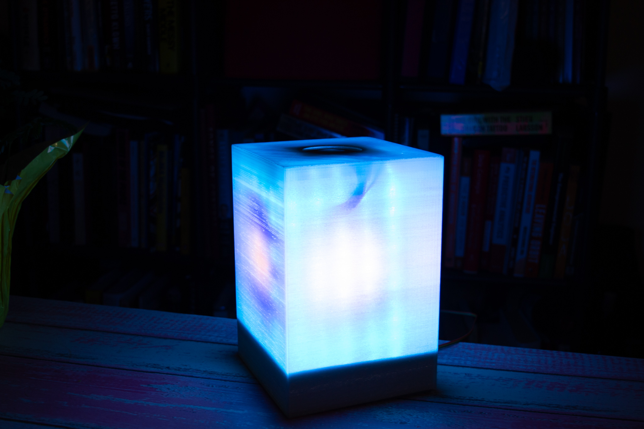
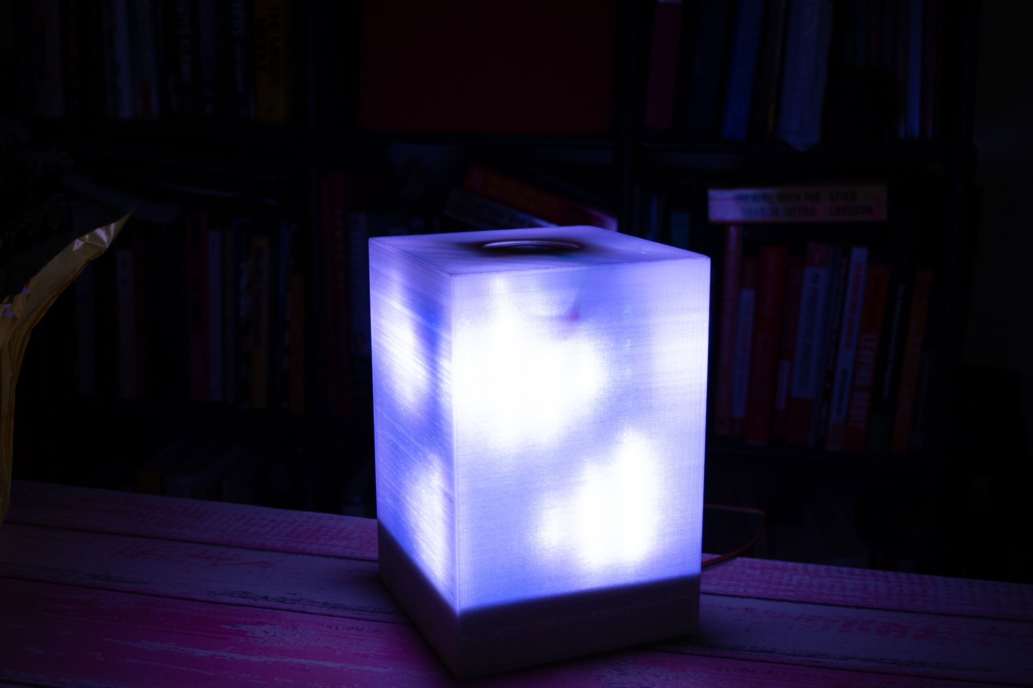
The lamp case was designed using AutoDesk Inventor and comprises three parts, the lamp base, the LED matrix mount and the lamp cover. The dimensions of all these parts were dictated by the dimensions of the LED matrix.
The parts were 3D printed using a transparent PLA (Polylactic Acid) filament for the cover and a silver filament for the base and LED mount. To obtain the right percentage of light diffusion, the case was 3D printed with a 60% infill and 0.2 mm layer height.
The figure below depicts the rendered 3D printed parts designed for this project. The 3D printable files can be downloaded from this Google Drive folder.


LED Matrix Design
The main technical detail to consider for the LED matrix design is the maximum current that can potentially draw. In our case we used a NeoPixel WS2812B strip. One LED of this type can draw up to 60 mA when illuminated with maximum luminous intensity of the three colors, according to its datasheet. Taking this into consideration we limited the number of LEDs to 200, which resulted in 50 per side of the lamp. Thus, the lamp has one LED matrix per side, each matrix is composed of 50 LEDs arranged in a 10 rows by 5 columns matrix.

All sides of the cube replicate the same information using the same data line. To accomplish this, we connected all the power, ground and data leads together to one another. The data lead sends the information bit wise to the LED matrix, in this case we would send information prominent to one side of the cube which will in turn then be replicated in all other sides.
We developed an algorithm to control each individual LED in the matrix, for this purpose we identified each column, starting from left to right, as the “x” coordinates and each row, staring from top to bottom (as seen in figure 3) as the “y” coordinates. For instance, the top row LEDs correspond to coordinates (1,1), (2,1), (3,1), (4,1) and (5,1) and the bottom row LEDs would in turn correspond to (1,10), (2,10) and so on.
The mentioned algorithm takes the x-y coordinates and the RGB intensity values of the LED to be illuminated as input parameters. Something important to mention is the fact that the LED control data-stream is very sensitive to time, and in particular to for/while loops, therefore we had to limit to the maximum the use of loops when controlling the LEDs, otherwise we got erratic LED operation (in color and position).
TFT Display
The 2.2" display has 320x240 color pixels. The TFT display is placed on the top of the cube. The display show the current time flashing on and off every second with precision up to the minute; in addition it provides the outside temperature in Fahrenheit. The display communicates with the microcontroller using 4 wire SPI.

Soft Potentiometer
The circular soft potentiometer was used to select the desired color that would be present in the lamp. The potentiometer has a 10K ohms resistor seen across the ground and vcc (3.3v) leads, the middle pin has a varying resistance with respect to ground and vcc depending where the user presses. When not pressed the middle pin floats. In order to use accurate values reading the middle pin a 220 ohms resistor connected to ground so that the reading would then be 0 if the potentiometer is not pressed and not floating.

HM-10 BLE Module

Microphone amplifier
We used an electret microphone to detect claps, and used the circuit built by the Black Hat Cats, Alberto’s ECE 3400 team in Fall 2018:

With this circuit, we were able to observe the amplified sounds caused by the claps, and regulate the gain of the amplifier to avoid picking up surrounding sources of noise. We used the oscilloscope to determine where to set the thresholds that distinguished a clap from other sounds.
The sound spectrum of a clap was analyzed in an oscilloscope. It showed that the clap, as a shockwave, had frequencies of similar magnitude across the spectrum. Hence, the Nyquist rate for sampling was not very critical. Thus, we decided to run the thread at 1kHz to ensure the sound was properly sampled. Every time the thread was executed, the output of the amplifier circuit was read by the ADC. When reading the voltage, spikes were observed corresponding to the moments when claps occurred. These spikes were significantly larger than the noise levels in the system. This helped us determine the thresholds for clap detection.
Results
Our system was remarkably stable, except for flickers in some of the LEDs. Other results were discussed in previous sections, or will be further elaborated in the conclusions below. Here is our video demonstration:
Conclusions
DOLORS performed as expected. We would have liked to include the microphone circuit and be able to use clap activation. However, we kept exploring causes and possible solutions for this issue even after the demo. We concluded that it was most likely an issue with performing ADC reads from different ports in different threads, and could have been solved by integrating them into one “adc_thread”. Another takeaway is that NeoPixels are very sensitive to timing and power. We observed all sorts of unexpected behavior when testing different animation modes, which ranged from flickering to LEDs displaying undesired colors. Even using jumper wires of different thickness would affect the behavior. To mitigate this, we placed a 10uF capacitor across the power rails to reduce the noise. For future projects, we recommend doing this, in addition to a larger power supply (we used 5V @ 2A). Routing power to each LED matrix separately can help in diminishing the amount of current running through one single wire and can potentially help with noise issues and inconsistent behaviors in the LEDs.

Our code uses several code examples present in the 4760 course website as the baseline for configuring and developing the threads.
We adhered to the IEEE Code of Ethics during the realization of this project. We didn’t harm anyone physically or otherwise, we didn’t make any false claims in this report that would cause misinterpretations of the work performed, we developed the entirety of our code, only using the references below as guidelines for organization and understanding of their functional principles. Since we used an HM-10 BLE module we could be subject to the FCC Part 15 rules, but we are not using the module to transmit, but rather to receive only. The onboard BLE module on the Raspberry Pi is FCC compliant, and it is a ubiquitous device that’s been thoroughly cleared in all related legal respects. Wires were not connected to persons or automoviles in this project.
Apendices
Appendix A
The group approves this report for inclusion on the course website.
The group approves the video for inclusion on the course YouTube channel.
Appendix B
Here is our final code: https://github.coecis.cornell.edu/al2367/ECE-4760/blob/master/final_project/final_build.c
Appendix C

Appendix D
Bill of Materials:
- Circular Touch Sensor, Rotary Soft Potentiometer - $ 12.96
- 3D Printed Lamp cover (Semi-clear light fading effect) - Maker Lab
- RGB LED strip - $ 33.00
- 5V DC adapter - $ 5.00
- Small Board - $ 4.00
- Jumper Cables (20)- $ 2.00
- White board - $ 6.00
- PIC32MX250F128B - $ 5.00
- MicroStickII - $ 1.00
- TFT LCD - $ 10.00
- Total: $78.96
Apendix E
- Alberto Lopez Delgado: Bluetooth connection, TFT Display , Microphone (clapper) circuit and implementation, potentiometer integration, power routing noise reduction.
- Wilson Llivichuzhca: LED control, LED matix implementation, 3D printed design, power routing noise reduction.
- Carlos Gutierrez: Animations development, potentiometer circuit and implementation, LED control, power routing noise reduction.
References
https://hackaday.com/2018/01/14/pi-weather-lamp-puts-lava-lamps-to-shame/
https://www.adafruit.com/product/1069
http://people.ece.cornell.edu/land/courses/ece4760/PIC32/index_pixel_strip.html
https://cdn-shop.adafruit.com/datasheets/WS2812.pdf
http://people.ece.cornell.edu/land/courses/ece4760/PIC32/Pixel_Strip/Neopixel/neopixel_packet.c
http://arcbotics.com/lessons/mixing-colors-with-the-rgb-led-2/
http://tahmidmc.blogspot.com/2014/10/interfacing-color-tft-display-with.html
https://openweathermap.org/api
Acknowledgements
Our team would like to acknowledge Professor Bruce Land and the TAs who stayed long hours in the lab with us, helped us debug hardware and software, and kept us sane altogether. Thank you!
Special thanks to Professor Skovira for allowing the collaboration between the final projects for ECE 4760 and ECE 5725. And to Juan Joel Albrecht for contributing with integration between both projects.
- All
- GUI
- Lamp
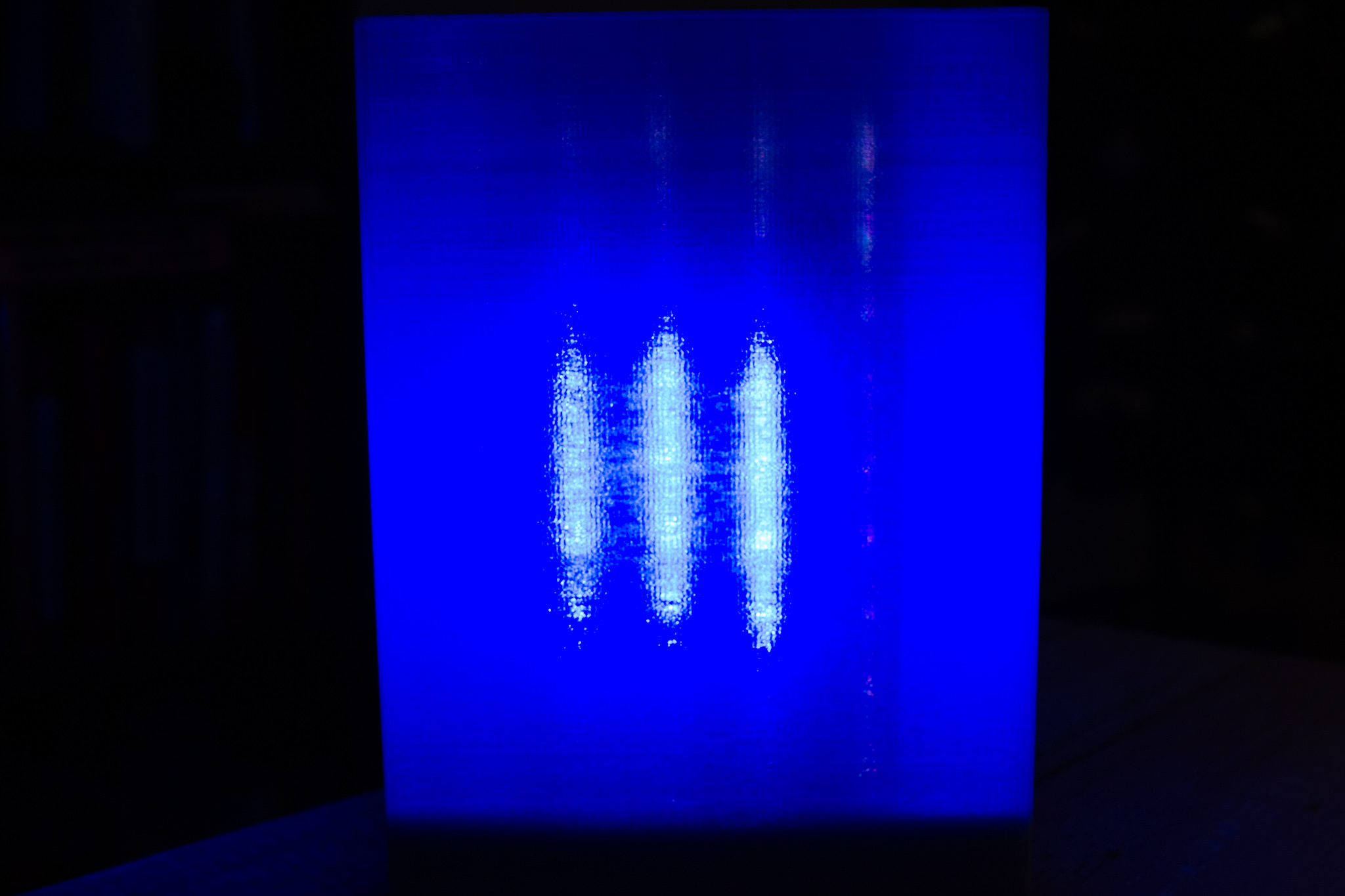
Blue Square
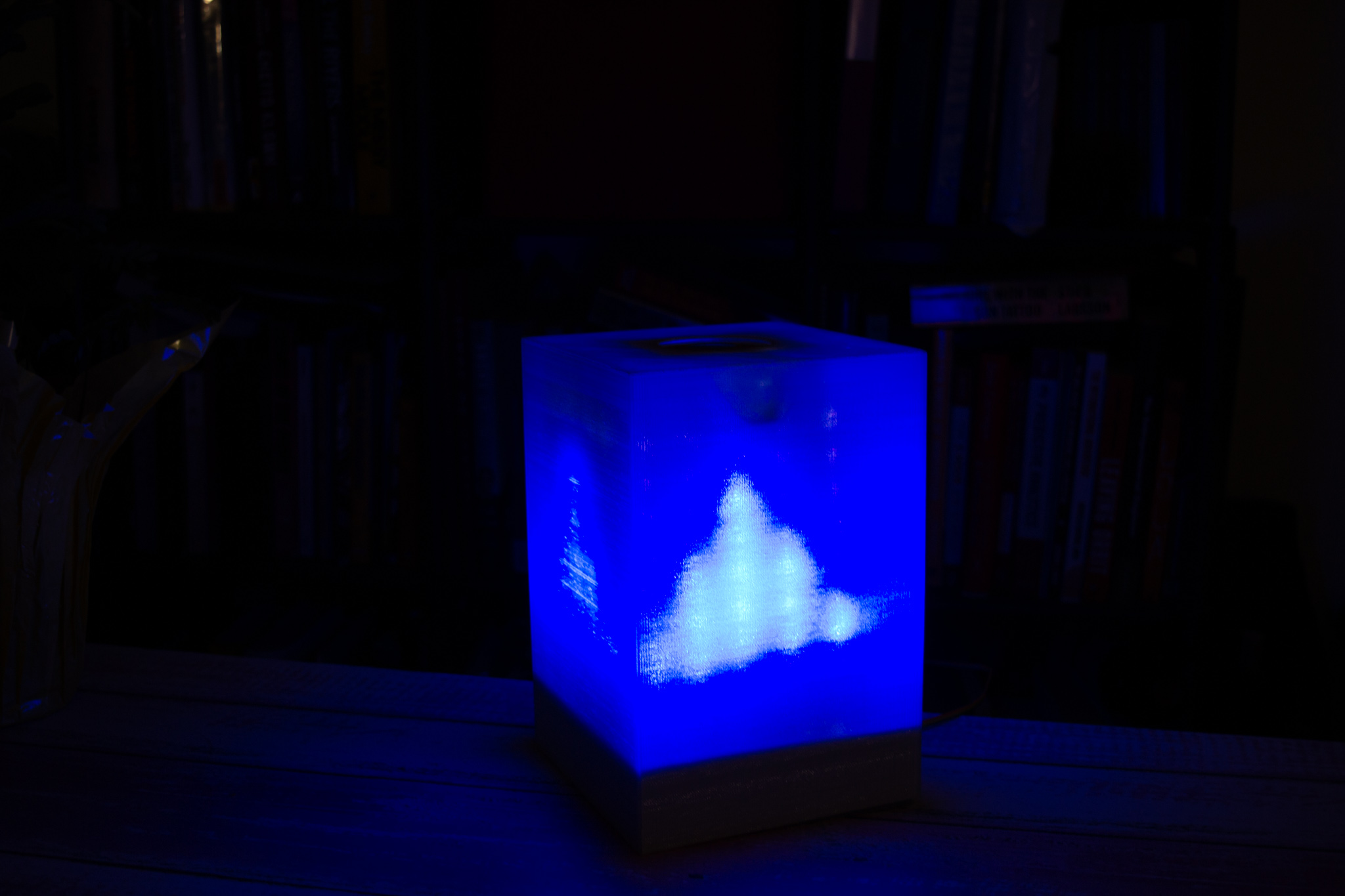
Blue triangle
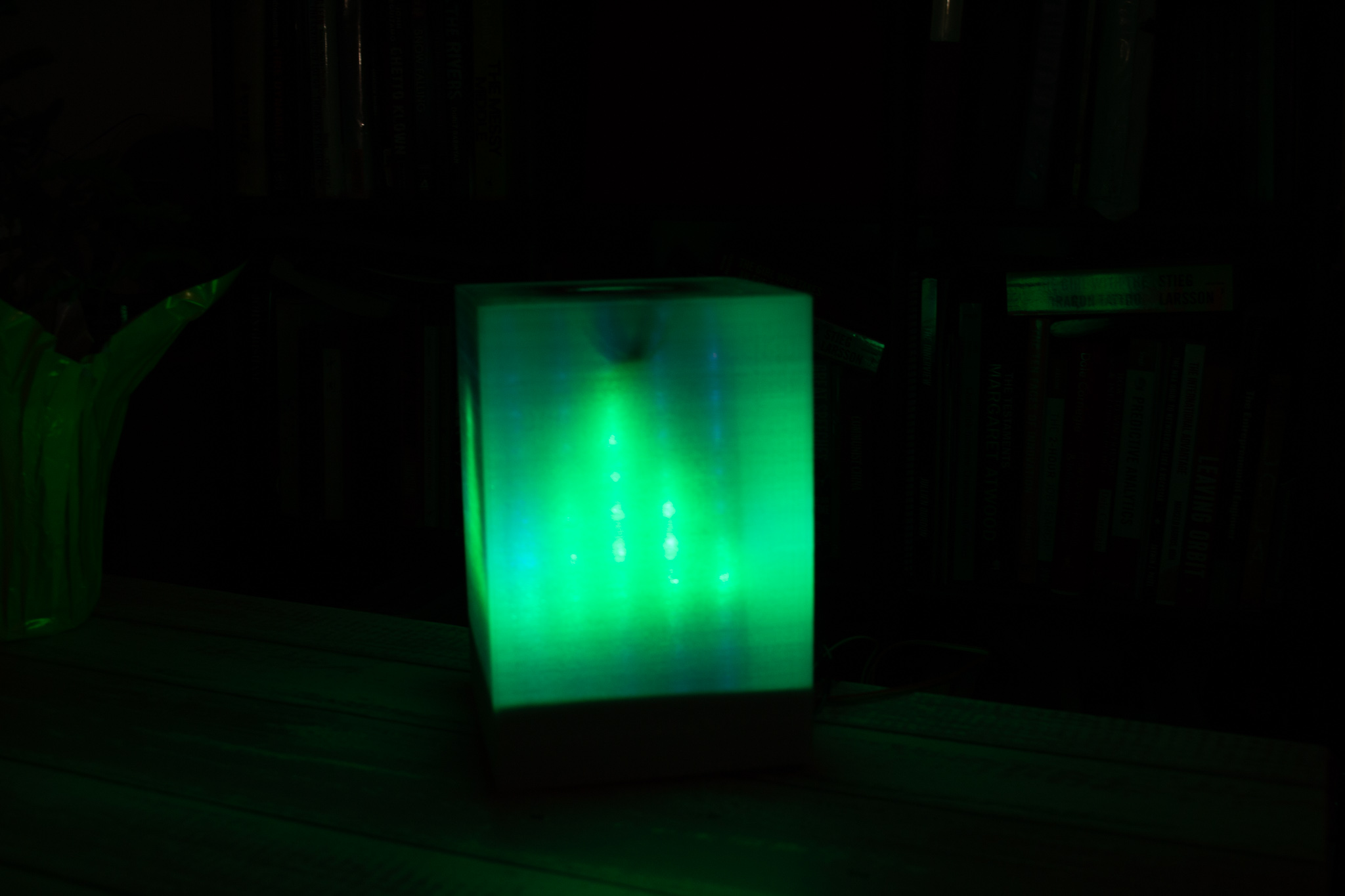
Green Square
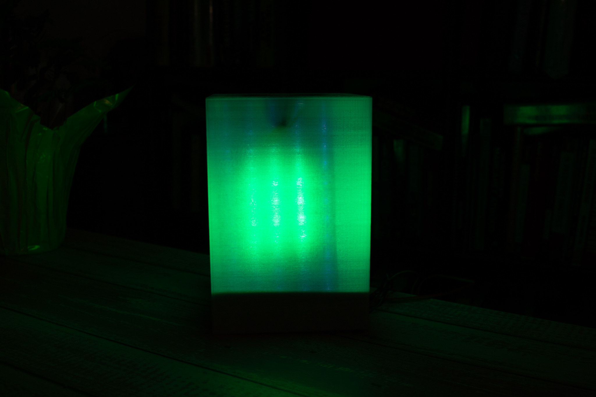
Green Triangle
Red Square
Red Triangle
Clear
Clouds
Rain
Snow
Blue
Green
Pink
Red

Yellow
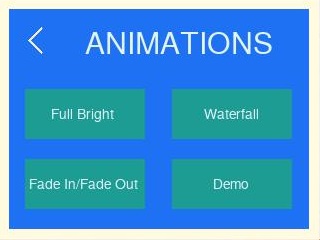
Animations
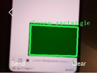
Shape detected
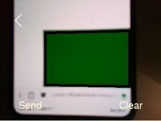
Detecting shape
Main Screen
Highlighted Button

Turn-on screen