Play Your Cards Right
Eric Ma (exm4), Vaishnavi Dhulkhed (vd89), Joy Thean (jct263)
Introduction
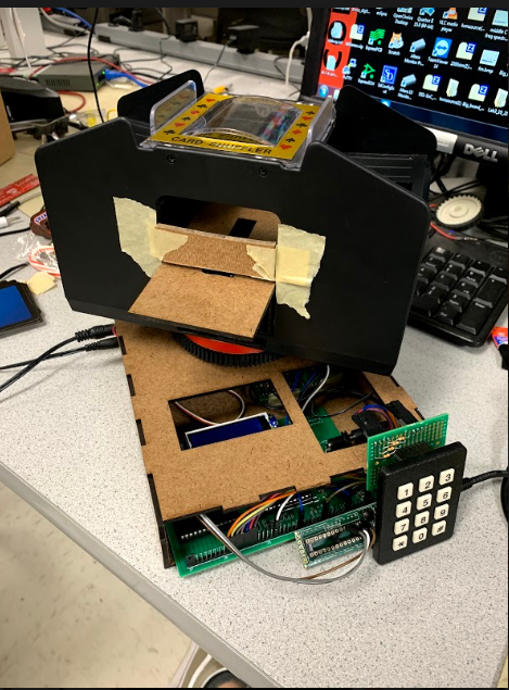
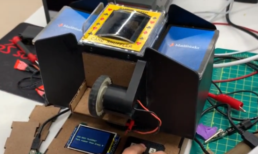
The purpose of this lab is to build a machine that alleviates the process of distributing cards in gameplay with a given set of players in random order. Our team has successfully built a prototype of such a device that takes in a deck of cards and randomly distributes them among players and deposits a pile in the end that will be used throughout the play. In our project proposal, we had proposed a multi-shuffle machine to increase the randomness and improve the shuffle for a deck of cards. However, due to mechanical difficulties as explained in the mechanical section, we decided to remove that aspect of the project and instead focus on a random deal to account for removing this feature. To utilize this shuffler, we integrated the TFT display to display the questions and the status of the shuffler. In addition, we integrated a keypad in which the user can enter the number of players and the number of cards they would like to deal to each player. Then, the machine will shuffle the deck of cards and deal cards to each player, one card at a time. Our machine works well and keeps track of the number of cards each player has been dealt and then once all cards have been dealt, the machine deals the rest of the cards to a “pile” between player 1 and player 2. As this is a one deck shuffler, we installed limitations in our code to handle only 52 cards where it was for shuffling or dealing.Meet the Team!

Eric Ma
Eric is majoring in ECE with a minor in CS and business, and is expected to graduate in Spring 2021. He enjoyed working on CAD designs for countless hours only to find that laser cutting was the move for most of the project. In his free time, he enjoys playing frisbee with his team and building household electronics for his mom.
LinkedIn
Vaishnavi Dhulkhed
Vaishnavi is studying ECE and is expected to graduate Spring 2021. Her favorite part of the project was watching it all come together with a huge improvement curve one hour before the demo. She also loved working with her team and loved how much she learned. When she has free time, Vaish likes to watch Netflix and improve her acting skills.
LinkedIn
Joy Thean
Joy is majoring in ECE and minoring in ORIE and CS. She is expected to graduate in Spring 2021. She loved getting close to this team over the course of the class and also seeing so many fun, different ways of integrating interesting systems with microcontrollers. In her free time, she likes to read and watch movies.
LinkedInHigh Level Design
Some of the hardware/software tradeoffs included the number of pins we were provided in the Big Board. As we were limited by the type of pins we could use to develop the circuit, there were some restrictions while building the hardware and developing our code. In addition, due to hardware limitations such as the max speed the servo could rotate or the max distance the DC motor can push a card out, we had to adjust our project accordingly. For instance, in the beginning, we had not accounted for Ball Bearings while building this design and then found that the servo we had bought was much slower than we had envisioned and that we required ball bearing to rotate the entire system at a reasonable speed. Thus, we adjusted our project and reformed our expectations and design based on the hardware and software limitations we faced.
In relation to other automatic card shufflers and dealers, we believe that our card shuffler and dealer is competitive but will need to improve in speed and accuracy to be competitive enough for the market. For instance, the Card Casino Shuffler referenced in the Appendix is a very slow shuffler. So, compared to such shuffler, we believe that our device performs at a faster rate. That shuffler may be more accurate but to account for this loss in accuracy, we implemented the random deal. On the other hand, the automatic cards dealing machine referenced in the Appendix deals much faster and with better accuracy than our system. Therefore, in the future, we would need to improve the speed and accuracy of the system to be competitive with our market.
Weekly Progress
What we achieved
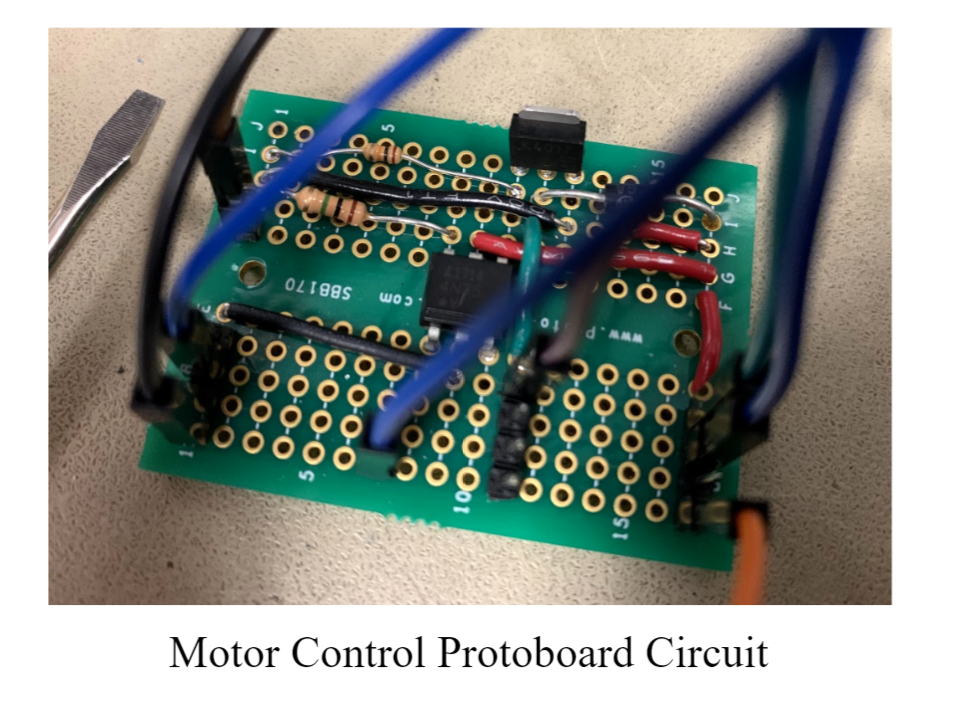
Tested various DC motors with electrical tape to see how to integrate with card dealing Bought a card shuffler, took apart to figure out the internals, planned how to integrate motors based on design of shuffler (includes gear system and motor placement) Rebuilt lab 3 motor control circuit to run motors, replaced bought motor control system with big board PWM control system Begun planning CAD parts necessary, planned out design for entire system involving how many motors are needed, how to lift center panel, etc.
What we plan on doing next week
Finish PWM control to be able to control our own shuffling Finish rough draft CAD model of entire system to prepare for printing. Decide how much of bought system we will continue to use and how much we will scrap Experiment how to set up dealing system, how to deal one card at a time reliably Finish designing deck separation system Work with a stepper motor, see if we can move big system to separate dealing
We are a little behind schedule due to us all being busy, but we have made good progress and expect to be on track/ahead by the end of next week.
Progress Report 2
What we achieved
On top of what we had achieved last week: Soldered find PWM control circuit onto solder board Tested PWM control and finalized code and hardware for controlling motor speed Ran Code on how to run a servo motor which we plan to use for turning the system back and forth during dealing Experimented dealing system with servo motors and stepper motors and found that servos work better Printed the deck separation system and will test it tomorrow during lab
What we plan on doing next week
Build an H-Bridge to turn DC motor in both directions which will be used to shuffle on both sides on the separation system Finish CAD for the dealing portion and send to print - CAD lazy susan with gear tracks on the sides Finish constructing the motors used for shuffling section including two dc motors to shuffle in cards One dc motor to shuffle cards on both sides of the separation system two servos to lift the cards up and down Assemble the shuffling section completely by the end of next week
We are getting back on track but are still facing several issues with the mechanical assembly. In terms of the electrical or code aspect, we believe to be on track. We hope to finalize our plan and resolve our mechanical issues by the end of next week.
Progress Report 3
What we achieved
On top of what we had achieved last week: Soldered two more PWM control circuits onto solder boards Tested PWM control and finalized code and hardware for controlling three separate motors Wrote code to control the software states of the system Experimented dealing system with servo motors and stepper motors and found that servos work better 3D printed our rotating base Tested ball bearings but decided to not use them because they made the system worse Laser-cut the extended base of the mechanical assembly Soldered the Keypad system to control the number of players and number of cards per player before the shuffler begins
What we plan on doing next week
3D print more parts of our mechanical assembly Completely assemble and test dealing section Assemble a rotating base and add an extended part to mechanical assembly Test and fine-tune rotation of the full system Have a fully functioning prototype to test and debug Make adjustments to PWM motor control signals
We are still facing a few issues with the mechanical assembly, but more of it is coming together now. In terms of the electrical or software aspect, we believe to be on track. Due to mechanical issues, we might have to drop the multi-shuffle addition to our project. We hope to have a fully functioning prototype by the end of this week.
Mechanical
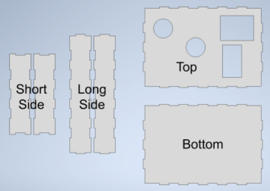
The base:
The base is made out of laser cut MDF. The box itself is a 16 cm x 24 cm x 3.8 cm, which houses our big board, power board, motor boards, and turning servo. Our initial plan was to 3D print the base of the box, but when considering time and material costs, chose to use laser cut materials instead. The box panels were designed to be a slotted edge design, that interlocked to create the final structure. The blueprint we used to laser cut is shown below:
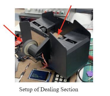
The Shuffler/Dealer:
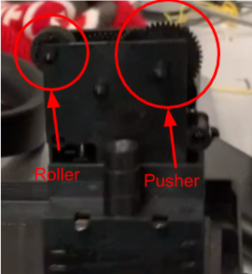
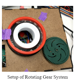
The shuffler itself is a card shuffler found on Amazon. This shuffler takes two motor systems, and pushes two split decks of cards into a central compartment. The gear systems inside consist of a roller in the front, and a lifter wheel in the back that bumps the cards up to push them closer to the roller. When testing the initial system, we purchased a two-deck shuffler, but we later purchased a four-deck shuffler, due to having more room in the center for us to fit our dealing mechanism. Below is the gear system we used to shuffle and deal cards:
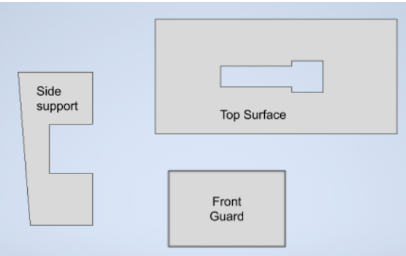
In order to deal cards, we implemented a two motor system. Our first step was creating a structure in the center area of the card shuffler, where cards would be pushed out to be dealt. We created a structure that utilized the shuffler motor gear system shown above, but angled to point outwards. We also made a stand and a large sloping surface, so that the cards could slide out and be dealt out faster with an external motor. The laser cut blueprints are shown below:
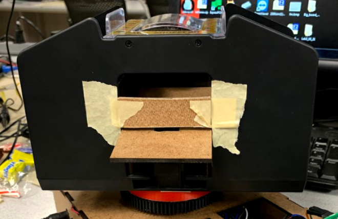
This entire structure was glued into the middle of the shuffler, with a motor system attached underneath to create the basis of the dealing surface. Below shows our dealing structure with a substitute front guard.
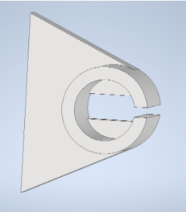
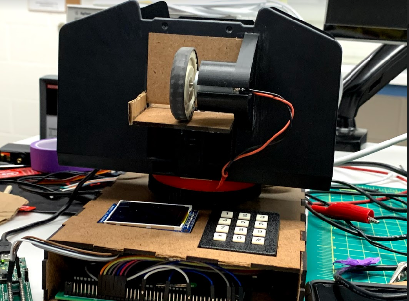
The final piece to the dealing structure is the shooting motor. A motor spins outside of the shuffler module as a whole, and is responsible for accelerating the cards out onto the table. This motor is held by an external attachment that was 3D printed, and spins a gear with a rubber exterior made to fling the cards that are pushed onto the platform out. Below is the final shuffle and deal structure, as well as the motor attachment design:
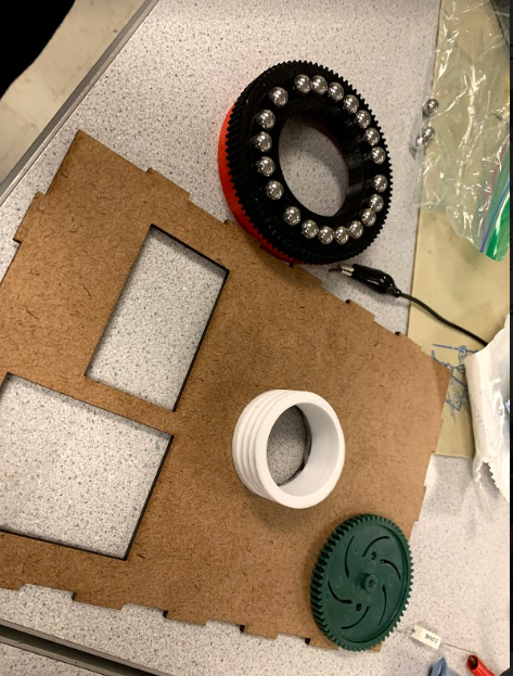
The Rotation Mechanism:
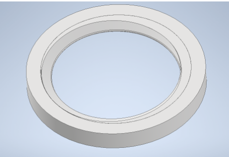
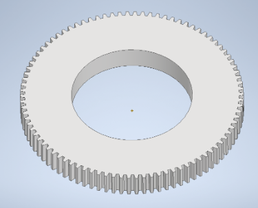
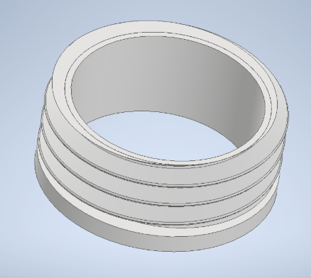
The rotational mechanism relies on a ball bearing gear system that rotates around a hollow tube. The gear itself connects to the shuffler mechanism, and is turned by a continuous servo attached to the base. To secure the gear and ball bearings to the base box itself, we designed the hollow tube with threads, and screwed down the entire structure so that the ball bearings could not escape. This hollow tube is used to run wires from the motor controllers to the motors in the shuffler. These rotational gears were 3D printed, and the ball bearings were purchased online. The gear structure is based on a Vex gear, and the main gear is designed with a 3:2 teeth ratio. The CAD designs for each part are shown below, as well as a video demonstrating the gear system by itself:
Overall, these three parts combine together to create the full system. The shuffler/dealer itself is responsible for handling the cards, the base is used to house the electronics, and the rotation mechanism allows for dealing in different directions. All parts were 3D printed or laser cut, and attached through glue.
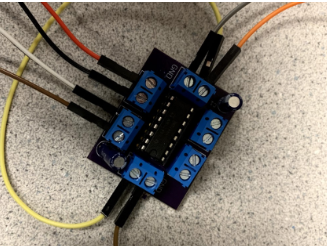
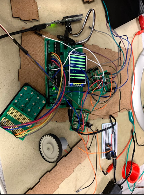
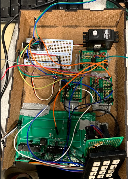
Hardware
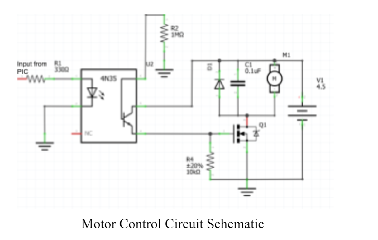
In general, for the motor control circuits, the PWM output from the PIC32 microcontroller is wired to a 4N35 optoisolator that connects the PIC32 signal ground to the DC powered motor ground. This optoisolator outputs our signal into a 2SK4017 FET. A diode protects the motor by preventing the flow of current the inductor creates when switching causes voltage changes to occur.
Shuffling
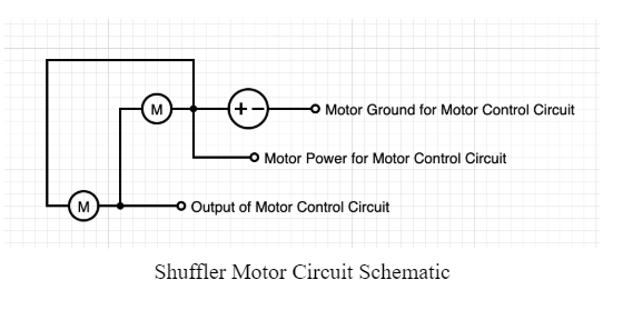
For the shuffling section, we built upon the system that was present inside the automatic card shuffler that we purchased as reference for our project. In the automatic card shuffler, there are two motors that each connect to their own gear systems on separate sides of the machine. The two internal motors used for shuffling were wired with opposite power and ground terminals. This was so that the two shufflers could rotate in opposite directions, thus rolling inwards, towards the center of the system. In making the motors PWM controlled, we wired the power terminal of one motor to the ground terminal of the other and then to the power terminal of a DC power supply. We then wired the other ground and other power terminals of the two motors to the output of a motor control circuit.
As part of our original idea for this project, we wanted to be able to shuffle multiple times which included raising a center platform to push cards against the ceiling of the system and rolling the cards to the right and left compartments with another motor. In order to achieve this, we built an H-bridge that would switch the polarity of the voltage applied to the motors. By using this circuit, we could reverse the direction that the motor was turning and run the motor forwards and backwards.
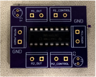
We connected the power and ground terminals of a motor to the terminals of the M2_OUT portion of the H-bridge while connecting the M2_CONTROL terminals to two arbitrary (we used RPA2 and RPA3 temporarily) output pins on the PIC32. These two outputs controlled the polarity of the voltage running through M2_OUT. When one pin was high and the other low, the motor spun one way. When the opposite was true, the motor would spin in the opposite direction. MOTOR_POWER and MCU_POWER were both connected to a 5V DC power supply except that the GND terminal of MOTOR_POWER was wired to the ouptut of the motor control circuit so that the motor could still be PWM controlled.
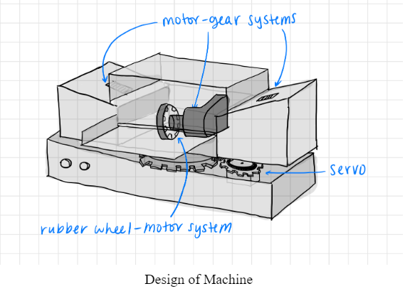
Dealing
Our dealing portion was split into two sections: one motor-gear system (same as the shufflers) and one motor with a rubber wheel attached. The shuffler-like motor-gear system is slotted in the low, center compartment of the body of the shuffler while the motor with the wheel is attached in the front of the whole system. These two motors have separate functions in this case. The motor with the gear system first pushes the cards forwards and out of the body of the machine. After a card slides out of the middle compartment, the wheel motor then uses the traction of the rubber around it to spin the card off the platform and forwards.
The motors used in this section follow the same hardware as the shuffling section except that each motor here are on their individual motor control circuits. We chose to separate the two motors here because we knew that during our fine-tuning stage, the motors would need to be tuned separately. This meant separate dutycycles and delays which meant different PWM controls and different motor control circuits.
Rotating
The rotating portion is a part of dealing, but the hardware for this section is different in comparison to how we controlled the rest of the dealing component. In order to rotate the whole machine, we used a gear system that is described in the Mechanical section. We connected a (green) gear to a Parallax Continuous Rotation Servo which served as the control for the rotation of the system. The power and ground terminals of the servo are directly connected to 5V and GND, respectively, on the PIC32 while the input of the servo is attached to pin RPB13 for PWM control.
Originally, the power and ground to the servo were connected to DC motor power and ground, but we soon realized that there was a lot of noise with this connection and every time we PWM controlled one of the other motors, the servo would also start rotating. We fixed this by isolating the servo’s power and ground.
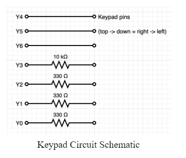
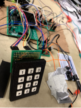
Keypad
The hardware for the keypad was identical to what we did in lab1 of this course. From left to right, we connected the keypad pins to PIC32 pins RY6-RY0. A resistor bridges the leftmost four pins of the keypad and the leftmost pins of the PIC32. 330Ω resistors between the first three connections and a 10KΩ resistor between the last connection. Pins Y0 to Y3 are outputs and pins Y4 to Y6 are inputs with pullups turned on.
Power Board
The power for the entire project was supplied through two barrel jack wall plugs used usually for our PIC32 big board. Since our motor boards operated on a separate power and ground to our signal power, we used two separate barrel jacks to create isolation from motor noise. We created a makeshift power board by using two barrel jack converters and breaking them out on an Adafruit protoboard. On one side, the barrel jack was broken out into two rows of female header connectors, one set for power and one set for ground. These header pins were used to power our four motors. The second barrel jack converter on the other side breaks out to power and ground, and connects to another male barrel jack, which connects to the big board. This serves as a barrel jack extender, so the board power jack can be accessed externally, instead of opening the box to connect the wire in directly. Pictured below is our power board, with motor power plugged in.
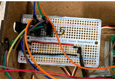
The barrel jacks were attached to the base box, and the side of the box had openings to access the barrel jack converters from outside, to easily power the entire system when fully assembled.
Software
Main and ISR Threads
During the first week, we mainly focused on the design and the mechanical setup and the software setup for the various motors. As described in the hardware setup, the shuffler motors were attached to OC1 in Group 1. The code for this set up is:
In addition, we set up the first dealing motor to OC2 in Group 2. This motor is meant to nudge one card from the deck. The code for this set up is:
Then, we set up the last DC motor to RB9 on the Big Board. Thus, we set up the last DC motor to OC3 in Group 4. This motor is meant to push out the card that has been nudged from the previous motor to the right pile. The code for this set up is:
Finally, we set up the servo in the last output compare. This motor is used for rotating the entire machine during the dealing portion. As we designed the machine to deal around a round table, the motor will turn based on the number of players in the game. The set up for this code is:
As you can see from the setup code from above, the shuffler motors are controlled by dutycycle, the first dealer motor is controlled by d_dutycyle, the second dealer motor is controlled by d2_dutycycle, and the rotating servo is controlled by r_dutycycle.
In addition, we set up the TFT and initialized the display in the main function since more than one thread uses the TFT display. The code for this set up is:
Finally, in the first week, we configured all the threads we needed for the project. As we understood that the project would be interactive, we understood that we needed software setup for the keypad. In addition, we created separate threads for the shuffling state and the dealing state. Finally, we created a thread to keep track of the state in which the machine was at. The state would be displayed in the TFT display. For example, if the shuffler was at the shuffling state, then the TFT would display “Shuffling…” . We then initialized the scheduler and scheduled based on the sched_rate. The SCHED_RATE determined which threads would be executed more often than others. For instance, if the rate of a thread was 0, then if would be executed more than a thread that has a rate of 1. Instead of the key thread, we wanted the rest of the three threads to be executed fast as it was updating states continuously either while shuffling or dealing. Thus, we set the SCHED_RATE to be 1 for the keypad thread and set the SCHED_RATE to be 0 for the rest of the threads. The code for this set up is:
After we set up in the main thread, we implemented the proper commands in the ISR. As we need to turn on and turn off the motors almost instantly, we decided to set the speed of the motors in the ISR. The code for this is as follows:
In addition, we set a parameter to control the number of cards the user enters. Thus, if the user enters more than 52 cards to deal per person, we set the deal_all condition to be true and just set the machine to deal the deck of cards equally among the players. We implemented this error check because our prototype is only able to shuffle and deal one deck of cards and thus, shuffling or dealing more than 52 cards would cause an error in our implementation. The code for this is as follows:
Keypad Thread
We implemented the keypad thread very similarly to the way we had implemented it in Lab 1. The hardware setup for the keypad is explained in the hardware section. On the software side, we had to first set up the keypad and set up the meaning of each key in the keypad. Finally, we had to understand the key that was pressed and correlate that key to the right parameters in the system. To initialize the keypad and understand the meaning of each key in the keypad, we created a keytable and defined the meaning of each key. The code for this setup is as follows:
The above code basically sets up the keys as they are displayed on the keypad. 0 corresponds to 0 and 1 to 1 and so forth. The shift keys are set up in the case in which we would need more keys to achieve our goal. However, as the project progressed, we realized that we did not require additional keys and thus did not set up the hardware for a shift key and did not use the last 12 keys in the keytable. Then, we set up PortY on the port expander as the keypad is connected to Pins Y0-Y7 on the Big Board. We set Bits 0-3 as inputs and set Bits 4-7 as outputs. Again in the software side, we had set up Bit 7 to be the shift key input but as we did not need additional keys, we did not set up a shift key on the Big Board. Then, we enabled Pull Up for Bits 4-7 and then initialized the other Z ports for other output functions. Although we did not need a detailed set up for this project, since we went off of the implementation from Lab 1, we included more software set up than we needed to. In the future, we plan to organize this section more to cater to our needs better.
Then, we set up for reading the button. The read-pattern if no button is pulled down by an output. This set up is beneficial to our project since we need to recognize when the user presses the keypad and thus causes a change in the state of the program. This section of the code keeps track of the read-pattern and sets keypad to the value that is read from the keypad. As shown in the code below, the keypad is constantly reading the Y port and once the user presses a key, the keypad is set and the program understands that the keypad has been pressed. The code for this is as follows:
Finally, in the keypad thread, once we understand that a key has been pressed, we implemented what to do with the value that is given. As we decided to implement the program so that the user can enter more than 9 players and more than 9 cards per player, the implementation of this part of the project was different from our implementation in the keypad thread from Lab 1. To account for debouncing and, we initialized another boolean variable named pressed. Thus, if the keypad is pressed for the first time, then only will the program change the state. Then, to account for more than 9 players or more than 9 cards per player, we asked the user to enter the number and then press #. This key corresponded to key 11 in our key table. Thus, if the key pressed was not #, the number incremented sequentially. For example, if the user wanted 12 players in the game, then the user would press 1, then 2, and then #. Then, in our program, we set the num_players to be 12 once the user hit #. To simplify this section, even if the user wanted to deal the entire deck, the user still had to press #. For instance, if the user wanted to deal the entire deck, then they would press * and then press # when the system prompted them to input the number of cards per player. Finally, we implemented global variables called ask_num_deal and ask_players which were set to 1 or 0 based on what state we were in. If the program prompted the user to enter the number of players, then ask_players were set to 1 and ask_num_deal was set to 0. These boolean variables helped us keep track of which variables to set to the number entered by the user on the keypad. The pressed variable was set back to 1 in another thread after a small delay to ensure that multiple variables were not set in one entry. Without the pressed variable, we were entering into state errors in which multiple variables such as num)deal and num_players were set with the same entry. The code for this section is as follows:
In this thread, we printed what key the user was printing on the TFT. This helped for both debugging purposes and for building a better user interface. The code for this is as follows:
State Thread
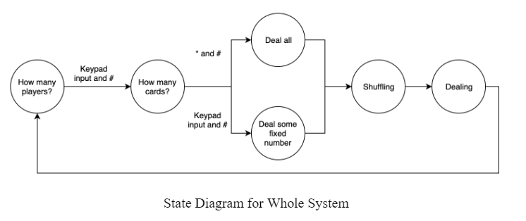
This thread was mainly used to control the state transitions both for the system and from the user’s point of view. In total, there are five states in this system: Prompt user for number of players, prompt user for number of cards per player, shuffling state, dealing state, and Deal Done State. In the first state, the TFT will display “HOW MANY PLAYERS?” The system will remain in this state until the user enters the number of players and hits #. Then, once the system registers the number of players in the game, the state transition to “HOW MANY CARDS PER PLAYER” in which the system is prompting the user to input the number of cards per player. The system waits in this state until the user hits # again. Once the system registers the number of cards per player, the system will transition to the Shuffle state. In this state, the program is looping through the shuffle thread, which is explained below. In this state, the user will be able to see the shuffling motors turn on and the TFT would display “Shuffling…”. Then, once the cards have been shuffled, the program exits the shuffle thread and enters the deal thread, which is explained in further detail below. While the system is in this state, the TFT would display “Dealing….” while the two dealing motors turned on and the rotating motor turned on for each new player in the game. When the Dealing state ends, the system enters the Deal Done state in which the TFT would display “DEAL DONE” for 3 seconds during which all the variables are reset and them prompt back to the first state in which the user is prompted to enter the number of players again. We are mainly using this thread to keep track of the various states and display the right commands on the TFT. We are also this thread to reset global variables that are set in other states. The code for this is as follows:
Shuffle Thread
The system enters the shuffling thread during the third state of the program. Until the third state, the shuffle thread yield to other threads. Then, to indicate the third state, we set ns to 1 in which the shuffle thread will no longer yield and instead turn on the shuffling motors. To turn on the motors, we set the dutycycle which controls the shuffling motors as explained above to the s_dc value. This value can be adjusted based on the weight of the card and the amount of tuning required to shuffle accurately. For our final demo, we set this s_dc value to 25000. Then, we yielded for the time it takes for the motor to push out half the deck of cards, one card at a time. This time was also calculated through meticulous tuning and testing. After we stalled for a certain amount of time in which we are sure that all the cards have been shuffled, we reset the dutycycle of the shuffler motors back to 0 and reset ns to 0 and set deal_start to 1. Setting deal_start to 1 indicates the start of the 4th state in which the system is ready to deal. The code for the shuffling thread is as follows:
Deal Thread
The fourth state is the dealing state. The system enters this state after the shuffling state under the assumption that the cards have been shuffled and are ready to be dealt. In all other states, the deal_start variable is 0 and thus this thread will yield until deal_start is 1. There are two sides to the dealing thread: deal all cards or deal only a set number of cards per person. The system would deal all the cards if the user enters * and then # in the second state or if the number of cards times the number of players exceeds 52. In addition, we implemented a random deal. To account for the loss of the multi-shuffle feature that we had originally envisioned, we implemented this random deal. The random deal means that the system will randomly pick a new player to deal the next card to. This random deal was implemented slightly differently based on whether the system would deal all the cards or only deal a set number of cards per person.
If the system is dealing only a set number of cards per person, the system will continue dealing until all players receive the set number of cards. A player is randomly picked from the total number of players for each card. Once a player has received the max amount of cards possible, then the system will eliminate that player and randomly choose from the remaining player. For instance, as you can see in our demo, the system randomly shuffles to player 2 and player 1 and player 3 in a random pattern. However, the system knows that it is done once all players have received their designated amount of cards. On the other hand, when the system is dealing all the cards, the system will pick a new player if the current randomly picked player has more than the 52/num of players + 1. We implemented this method because when all cards are dealt, most players get 52/num of players and some players get 52/num of players + 1. This small adjustment helped us achieve our goal of dealing the entire deck if the user intended to. The code for this implementation is as follows:
Then we implemented the rotation algorithm. For this, we calculated the difference between the current player and the previous player. Then if the difference is less than 0, then that means that the current player comes before the previous player and thus the system must turn counter-clockwise. On the other hand, if the difference is greater than 0, that means that the current player comes after the previous player and thus, the system must turn clockwise. Then, accordingly, we calculated the time it takes to rotate the system towards that player. Through meticulous tuning and testing, we calculated the time it takes for the motor to turn counterclockwise (called time_for_360_CCW) and the time it takes for the motor to turn clockwise(called time_for_360_CW). Then, we calculate the time it takes for the system to rotate by diving this time by the number of players. For example, if there are 2 players in the game and it takes 500 msec to turn clockwise, the time to rotate from player 1 to player 2 would be 500/2 = 250 msec. After calculating this time, we turned on the dutycycle for the rotating motor (rdutycycle) and reset it back to - once the system has rotated. The code for this implementation is as follows:
Then, during testing, we found that the motor was too powerful at a certain dutycycle once the deck of cards started to decrease. Thus, we accounted for the dutycycle for the dealer motors that both nudges and pushes out the card based on the remaining cards in the deck. This part of the code was heavily dependent on the type of cards we used. For the cards we used to test the entire system, this dutycycle and this algorithm worked pretty well. Through testing, we found that the system failed to work accurately once the deck of cards decreased by 10. Thus, we change the dutycycle of the nudge dealing motor and the dealing motor that pushes out the cards We set it to a new dutycycle that was determined through heavy testing and tuning and we decrement the dutycycle by 175 after each card has been dealt. Once a card has been dealt, the player_array increments the count for that current player and the increments the total card count by 1. The code for this implementation is as follows:
Finally, we ended this thread either when all cards have been dealt or all players have received the set amount of cards they must receive. The end of this thread is signified by setting deal_start back to 0 and setting restart to 1 in which the system enters the DEAL DONE state and all the variables are reset for a new game. If the system is not in the deal_all process and only a certain number of cards have been dealt to each player, the system deals the rest of the cards to a “pile”. The pile is dealt halfway between player 1 and player 2. The pile is meant to clear out the machine and also usually in a card game, we need a “pile” for players to continue playing the game. The system also rotates back to its original position. We decided to rotate the system back to its original position to improve the user interface of the system. The code for this section is as follows:
Overall, the software portion of this project depended heavily on the random algorithm that we implemented for dealing. In addition, one of the greatest challenges we faced was tuning this system. Since our motors are controlled by time and turn on and off based on the time we have tuned and tested for each deal, shuffle, and rotation, there is still a small amount of error in our system. To implement better software in the future, we would control the motors through another form such as sensors or other factors that will be more precise and thus give us more accurate results.
Results
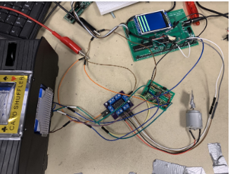
After we had achieved turning, we started putting all the pieces together and began to connect the board together. The board connections have been explained above in the hardware and software section. Thus, once we had finished completing the mechanical aspects of the project, we started to put all the pieces together and connected set up the board for tuning.
After we had set up the entire system, we began heavy tuning. In this process, we found problems in both the shuffler and the dealer. The shuffler has accuracy issues as cards were getting stuck and we had to increase the dutycycle of the shuffler. However, after hours of testing, we established a good shuffle by finding the right dutycycle and the right amount of time required to shuffler the entire deck.
Even on the day of the demo, we were facing tuning issues since the margin of error was high. When only one card should have been dealt, there would be no cards or more than 2 cards dealt.
However, after implementing the nudge as explained in the software section and understanding how the cards interacted with each other, we were able to decrease the margin of error and improve the accuracy of our machine.
Speed of Execution
Processing through each state of our system, we have in place a few delays such that the user isn’t disoriented by how quickly each state happens. This is because we realized that immediately when pressing the # key on the keypad, the shuffling begins. However, this is not user-friendly because there is no time for the user to ready themselves for the shuffling, thus the delays. In order to improve usability, we sacrifice a bit of our speed. The only issue with speed that we had was in the rotating of the machine. Due to poor feedback and torque, the servo turns one way very quickly but the other way incredibly slowly. In regards to the whole system, however, this difference in speed does not cause major performance issues, as we calibrated each rotation direction separately.
Accuracy
Overall, our system had a few issues with accuracy. The three main components of accuracy found within this shuffler is a proper shuffle, dealing the right amount of cards, and dealing the cards in the right directions. The first issue came from the shuffling itself. While a level of randomness to shuffling is desired to properly function, our accuracy came from dealing the cards to the center compartment in a consistent way that would not jam. Our shuffle stage would jam about 1/4th of the time. The biggest issue with dealing accuracy was the lack of feedback between the dealing motors and the output of cards. Due to jams or overactive motor behaviour, our final card output per hand ended up being ±2 cards per hand, which was more inaccurate than desired. While tuning was an important part to improving the accuracy, the issues arose from the variable nature of cards, with different attributes of friction and shape changing every hand. Finally, our rotational system would drift off angle as more and more turns were executed, due to the drag from the wires within the shuffler or the torque of the gears. With better feedback systems, we hope to improve the overall accuracy much more in the future.
Safety in Design
We enforced safety in our design by encasing our circuits and board within a box and allowing easy access to plug in the machine. By keeping any sort of circuitry away from the user, we completely take out possible electrical dangers that can come with exposed wires or pins. Also by utilizing DC barrel jacks, we further eliminate any risk of the user directly reaching into the hardware to power the system. Since the servo we used to rotate the system doesn’t have that much torque, there also isn’t any risk of the user getting caught in the gear system. While our system is sturdy and can’t be broken that easily due to the type of materials we used, it can also be stopped quite easily if the user blocks the rotation of the system with their hand.
Usability
In general, our project is relatively usable for people. There is a user-friendly display that takes the user through the different stages of how to use the machine and gives very clear instructions. We hid all the circuitry within a box that also served as the base of the machine. This way the user won’t be distracted or confused by an excess of wiring that doesn’t need to be seen by them. Regarding special needs, our project could improve our usability. For a blind or paralyzed person, they would find themselves having a hard time using our machine because it relies so much on being able to use the keypad feature. In the future, we could implement voice activation and voice over capabilities such that the user wouldn’t need to see the screen or even touch the keypad.
Conclusion
The standard that this prototype conforms to is a home setting. This prototype can handle one deck of cards and can deal out up to 52 cards. Thus, for large games in Casinos that require at least 8-9 decks, our prototype would not perform well. However, to increase these standards, we would have to increase the speed and accuracy of the shuffle and deal. As you can see in our demo video, the card shuffler takes more than a minute to deal 7 cards to 3 players. However, the average amount of time it takes for a human to deal 7 cards to 3 players would be about 30-45 seconds. Hence, to conform to applicable standards, we would need to increase the rotation and deal speed.
Intellectual Property Considerations>
The shuffler section of our project consisted of an automatic card shuffler that we had originally purchased for reference but ended up repurposing to become the body of our system. The automatic card shuffler we purchased is sold by GSE Games & Sports Expert. All code, except for any source files provided to us in previous labs by Bruce, and all CAD files are original work and designed by us.
Ethical Considerations
- To hold paramount the safety, health, and welfare of the public, to strive to comply with ethical design and sustainable development practices, and to disclose promptly factors that might endanger the public or the environment;
We certify that this project does not endanger the public or environment’s safety. - To avoid real or perceived conflicts of interest whenever possible, and to disclose them to affected parties when they do exist;
We certify that during the course of this project, we avoided any conflicts of interest when possible and relayed any issues regarding this when applicable. - To be honest and realistic in stating claims or estimates based on available data;
We certify that everything in this report and code is true to the best of our knowledge. - To reject bribery in all its forms;
We certify that the purpose of this project was purely academic and that no profit was or will be made. - To improve the understanding by individuals and society of the capabilities and societal implications of conventional and emerging technologies, including intelligent systems;
We certify that the goal of this project was to explore the possibilities of an interesting technological system and share any knowledge gained. - To maintain and improve our technical competence and to undertake technological tasks for others only if qualified by training or experience, or after full disclosure of pertinent limitations;
We certify that the goal of this project was to further our own knowledge of microcontrollers as well as help others in this effort whenever we could or were qualified to. - To seek, accept, and offer honest criticism of technical work, to acknowledge and correct errors, and to credit properly the contributions of others;
We certify that during the course of this project, we actively sought advice and suggestions from the teaching assistants as well as the professor. - To treat fairly all persons and to not engage in acts of discrimination based on race, religion, gender, disability, age, national origin, sexual orientation, gender identity, or gender expression;
We certify that during the course of this project, we treated all people we came into contact with fairly and without discrimination. - To avoid injuring others, their property, reputation, or employment by false or malicious action;
We certify that during the course of this project, we followed the all safety guidelines set by the class for working with electrical components or computers. - To assist colleagues and co-workers in their professional development and to support them in following this code of ethics.
We certify that during the course of this project, we supported our fellow student colleagues in their projects and provided assistance whenever we could or were qualified to.
Safety Considerations
To our knowledge, there are no individual parts of our project that are a danger to anyone. Open wires and pins are always a possible risk, but in the design of our project, we take necessary measures to hide away these parts so as to eliminate any possibility of safety consequences due to electrical components. Other than low-torque gear systems that have a low probability of catching hair, there are no parts of our design that could hurt anyone.
Legal Considerations
To our knowledge, this project has no legal considerations. We believe this to be true because our project does not directly attach to any person and does not utilize any communications or automotive systems.
Appendix
Budget Considerations/Cost Details

Breakdown of Tasks
Eric designed and made all mechanical parts of our project, including laser cutting and 3D printing. As part of the team, Eric was involved in protoboarding parts of the circuitry, specifically the motor control circuit, as well as debugging and fine-tuning the whole system after it was assembled. For the report, Eric wrote all of the mechanical design section and any other parts that needed work such as the conclusion.
Vaishnavi worked with Joy in writing the code and building the necessary hardware for the system as well as did most of the protoboarding. As part of the team, Vaishnavi was involved in debugging and fine-tuning the whole system after it was assembled. For the report, Vaishnavi wrote all the software design section and any other parts that needed work such as the introduction, results, high level design, and conclusion. Vaishnavi also set up the html file for the website.
Joy worked with Vaishnavi in writing the code and building the necessary hardware for the system as well as figuring out and debugging any new hardware we integrated such as the servo. As part of the team, Joy was involved in debugging and fine-tuning the whole system after it was assembled. For the report, Joy wrote all the hardware design section and any other parts that needed work such as the results.
References
- Peripheral Pin Select Output Table: Input/Output Table
- Keypad PIC32MX250F128B Page: Keypad
- Optoisolator Circuit from the 1DOF Helicopter Lab: PWM
- 1-8 decks Casino Full-Automatic card shuffler
- Amazing 1890 Automatic Card Dealing Machine! Banned by casinos.
- Wooden Card Shuffler
- Automatic Playing Cards Dealing Machine
- Card Shuffler by Shuffle Tech
- We based off of this automatic card shuffler: Auto Shuffler
- We utilized these Ball Bearings to enhance the speed of the rotation: Ball Bearings
- We used this servo to rotate the system to deal to different players: Servo