Persistence of Vision (POV) Dino Game

by Zesun Yang and John Ly

Find Out More

Introduction

Our project is a persistence of vision styled dinosaur game. Our team was really intrigued by POV displays and we wanted to explore how POV works. That’s what led us to this project. Unlike most POV projects we have seen on the internet that only plot static graphs, we designed a POV game that the user can interact with. The main character of the game is a green dinosaur, and it needs to dodge fireballs by jumping up. We used a box fan, a PIC32 microcontroller, an accelerometer and other sensors to create this cool game. When the user shakes the fan upward, the accelerometer detects it and informs the dinosaur to jump. It’s a fun project, and it’s also a good exercise for your arms.

High Level Design

High Level Design

1. Rationale and sources of the project idea

Zesun had seen a POV project demo in her Arduino class when she was a sophomore and was amazed by POV displays. She wanted to build something relates to POV for the project. We did research on the internet, and interestingly, most of these POV projects are either making a digital clock or only displaying a static image. We wanted a cooler POV project than just a clock or a graph. When we were searching for parts, suddenly the internet connection was gone and chrome jumped to its no-internet-connection dinosaur game. We were inspired by it and we decided we were going to make a POV version of the dinosaur game.

2. Background math

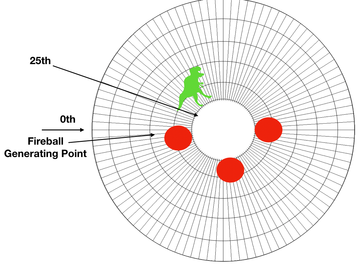
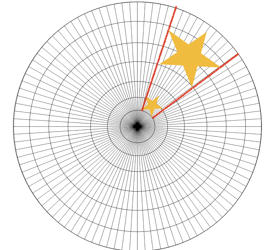
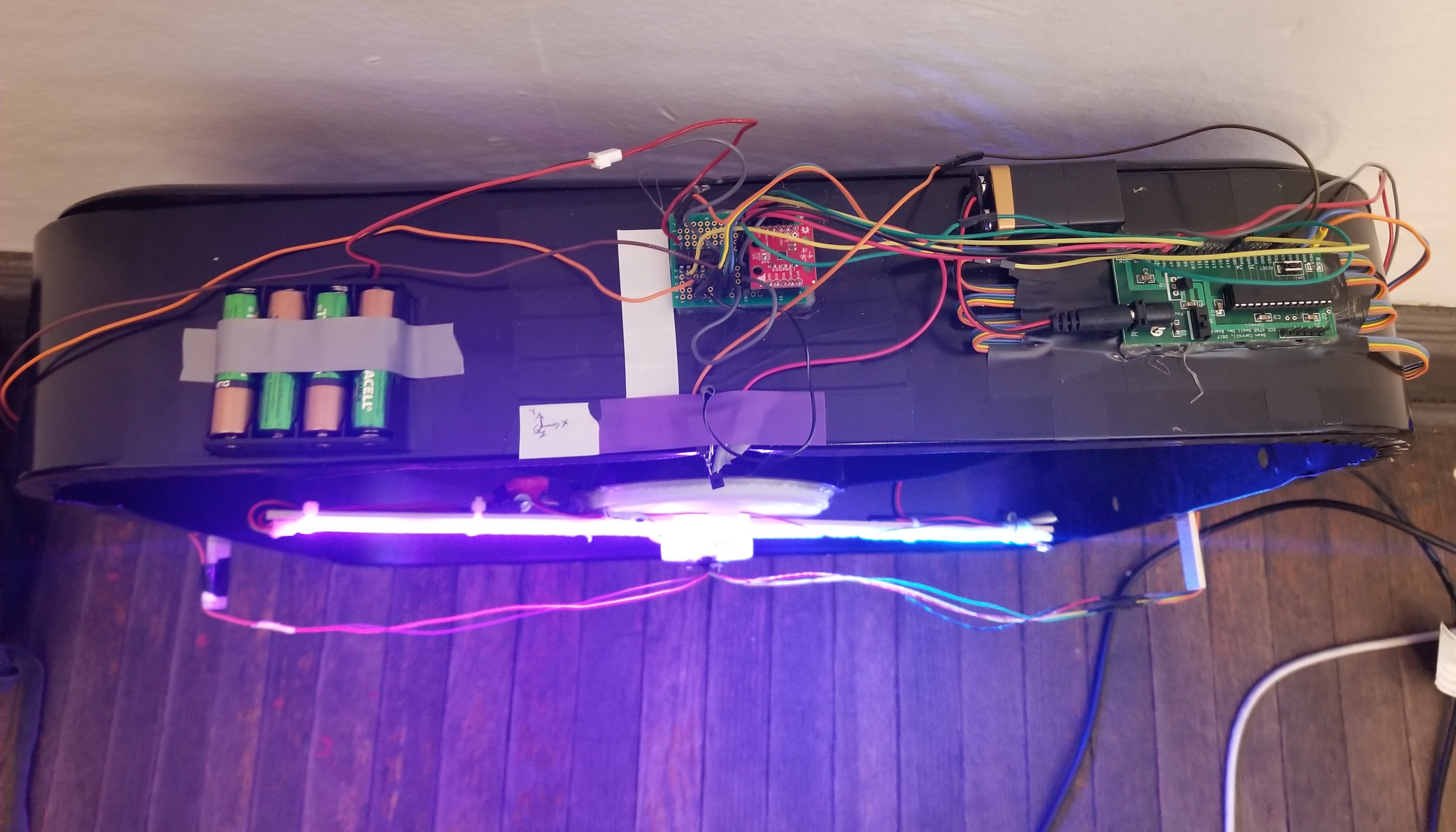
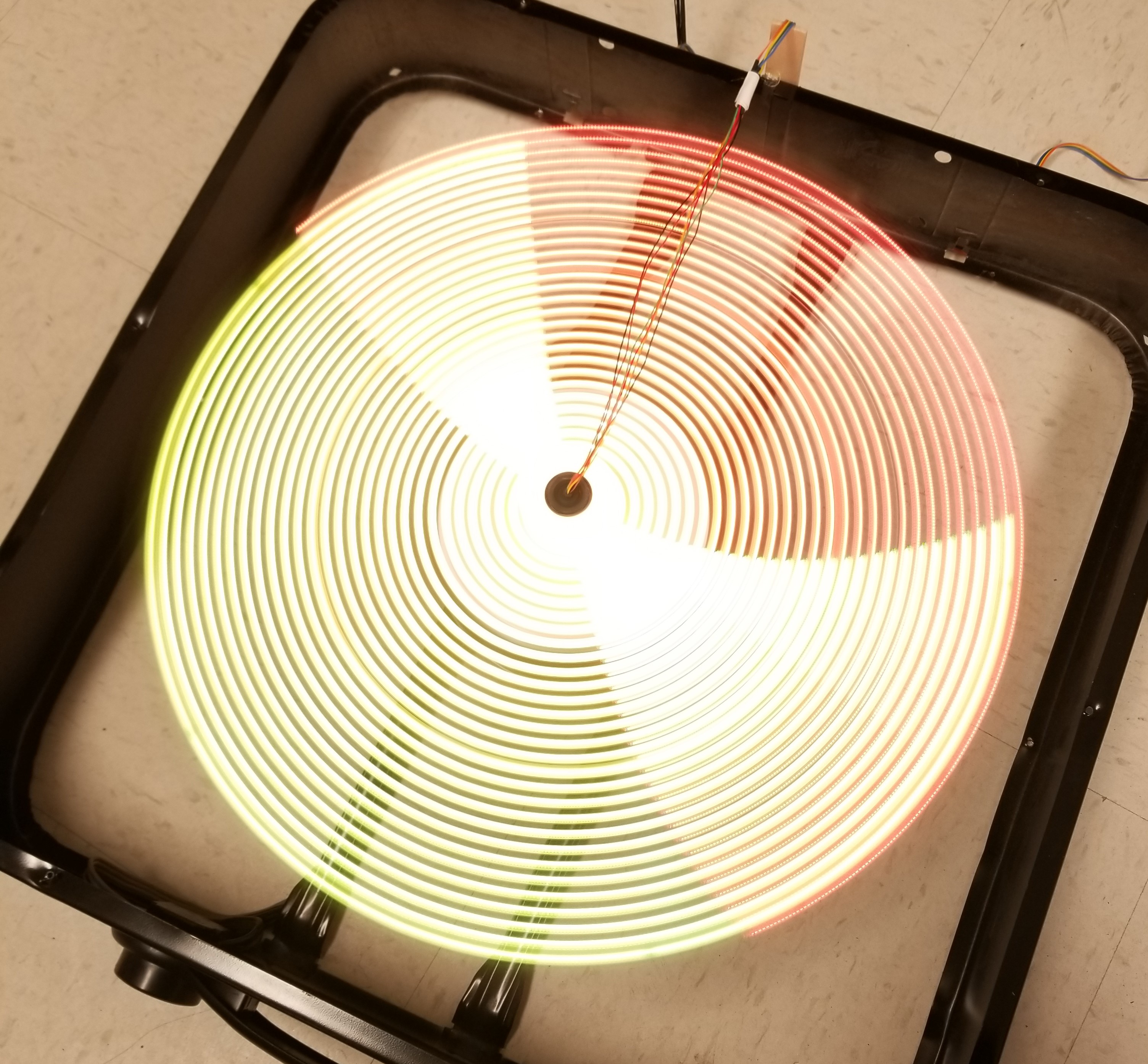
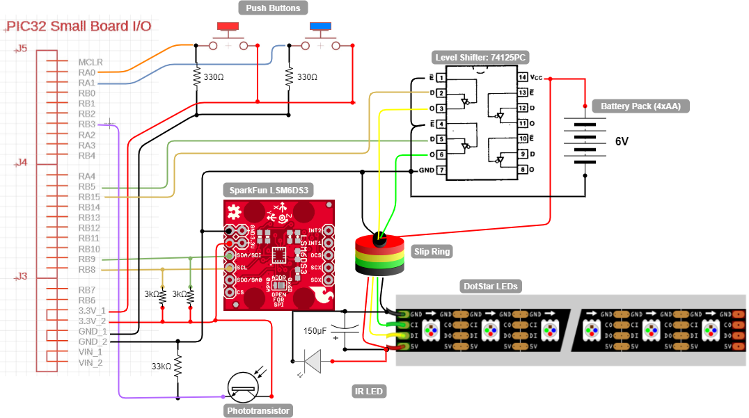
Phase lock was used to lock our game objects at a particular position on the POV display. Unlike a static TFT LCD display in which the pixels were set and not moving, we used a single DotStar LED strip which we rotated very quickly around an axis to make use of the persistence of vision effect and created a sort of ‘fake’ display. When capturing with a camera, it was can be very easy to make out the individual parts of the blade as the shutter speed is too fast, but to the human eye, the lit up pixels seem persist in our vision allowing us to piece together a full image. As the pixels on the DotStar were constantly moving,we needed to determine when to turn on specific LEDs to display our game. To achieve phase locking, we first calculated the RPM of our fan on its lowest speed. We used an IR LED and IR sensor to find how fast the fan rotated. We had a 32-bit timer (timer23) that every time the IR LED made a pass to the sensor, we determined the amount of cycles between each revolution and then reinitialized the timer to 0. The average readout value was determined how fast the fan was rotating. The RPM was calculated using the following formula: Period = timer23 value / 40 MHz [s] RPM = (60s/1min) * 1/(period) 40 Mhz was our CPU clock frequency; the readout value divided by 40Mhz gave how many seconds the fan took to go through one revolution. There are 60s in a minute. Mulitplying that by the frequency returns the amount of revolutions per minute for our fan. At the lowest speed, the readout we got was around 4528302, and that roughly corresponds to 530 RPM. After knowing the RPM at speed 1, and the max readout timer23 could have, we could perform phase lock by updating the DotStar at the right time. We knew timer23 reads about 4528302 for one revolution, if we wanted to update the DotStar 100 times per revolution, then the timer would read 4528302/100 = 45283 for one update. While we definitely had the processing power to update even faster every revolution, we determined that 100 updates provided us with enough resolution to display our game.

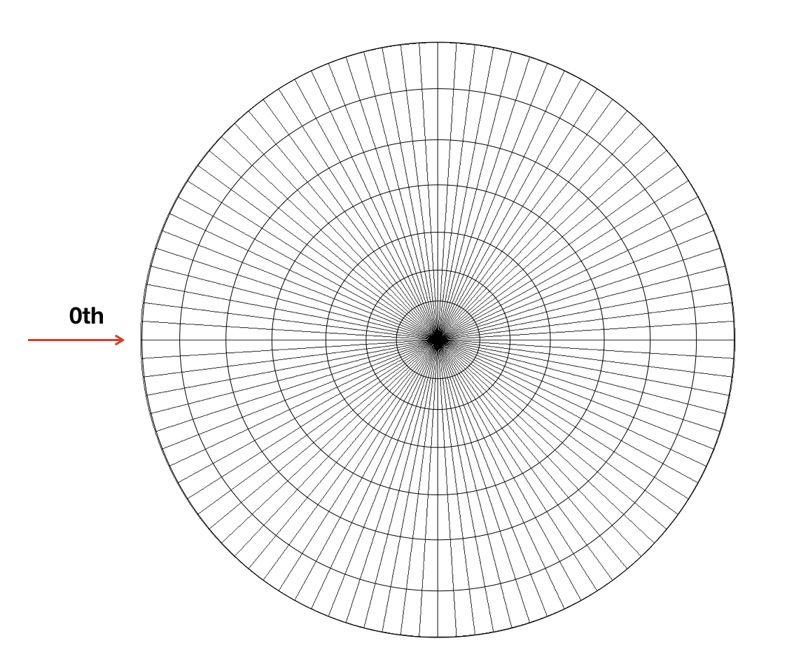
Figure 1. Example Fan with 100 updates/rev

The red arrow indicates the position that matches 0th update, the 1st update is the next vertical line and etc. This covers the math for our phase lock.

3.Logical structure

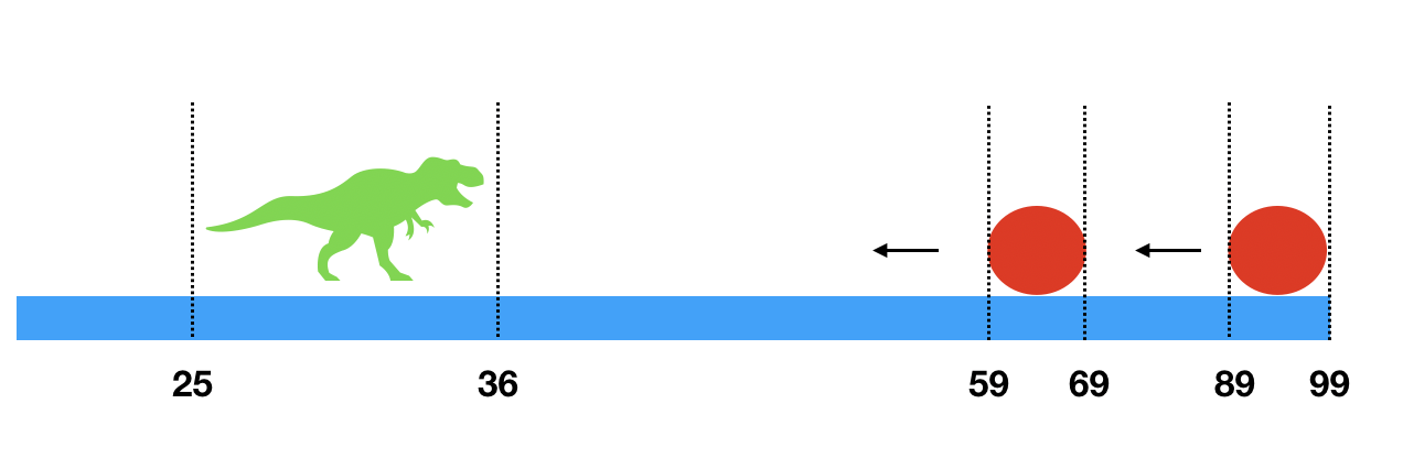
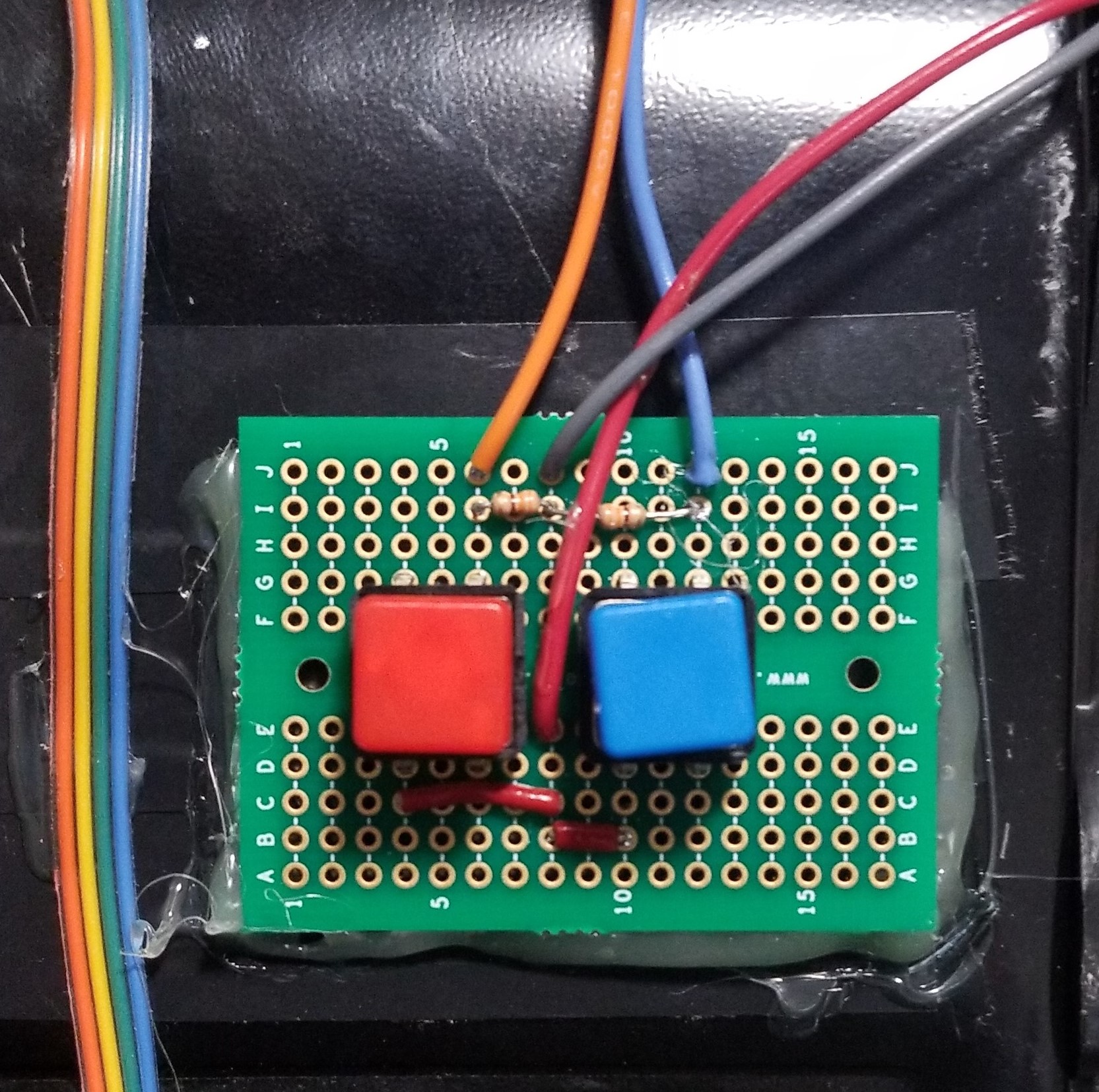
We had a thread responsible for game object calculation such as dinosaur jump, landing and whether it hits the fireball, and the same thread generates fireballs. More details of the game is covered in the software design section. We used two ISRs to control the timing of the game as well as the game console update. By separating the game object logic and the game object drawing, it was very easy for us to add and remove any part of the game as there were no heavy dependencies in the game.

4.Hardware/software tradeoffs

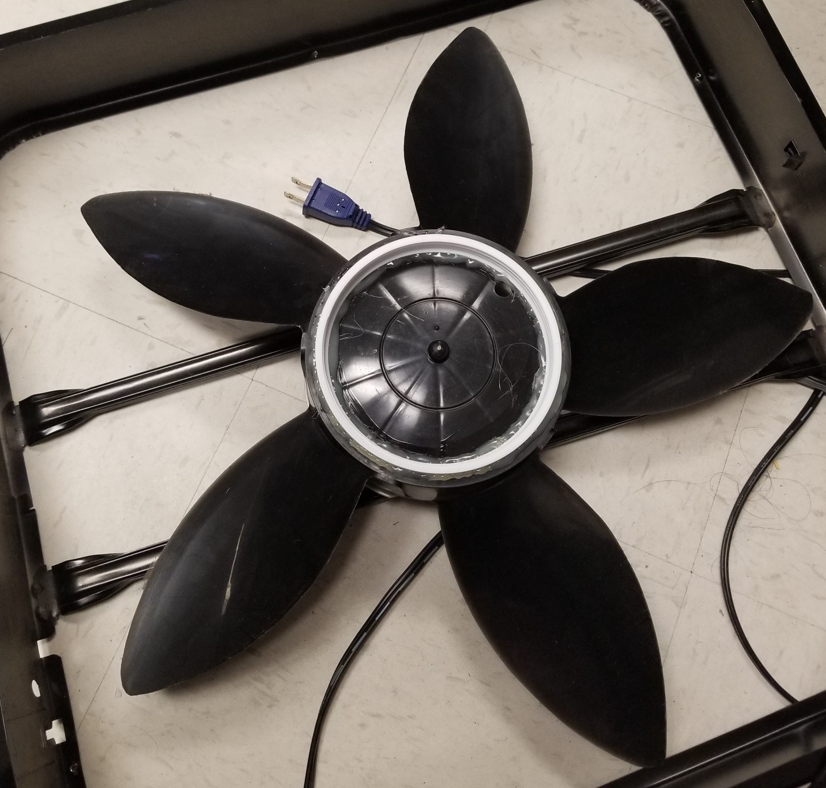
Although the fan had 3 levels of speed with level 1 being the slowest with 530RPM, it was hard to find a slip ring that met our budget limit that could perform more than 300RPM. We were overloading our $7 slip ring even using the slowest rotation speed of the fan.
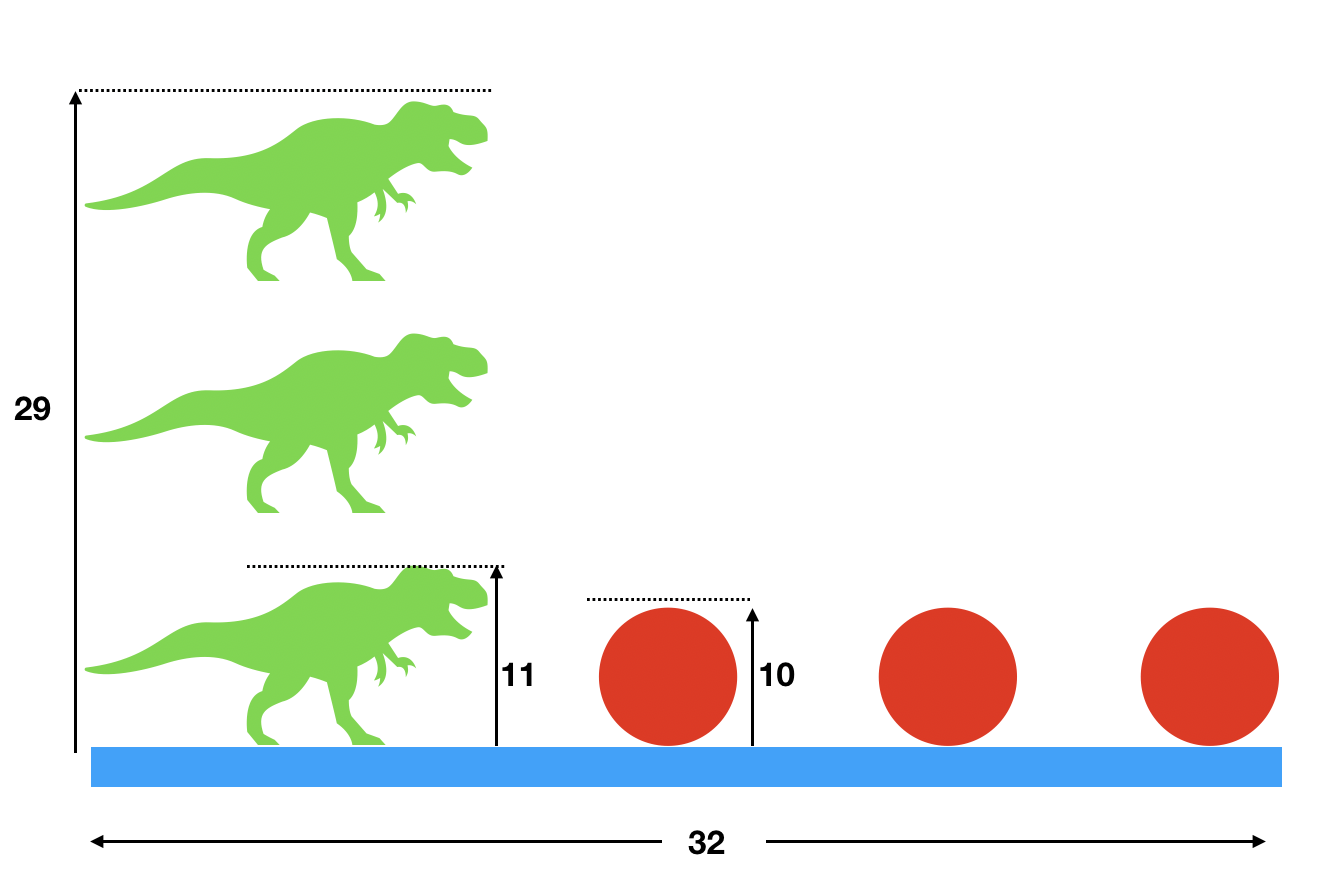
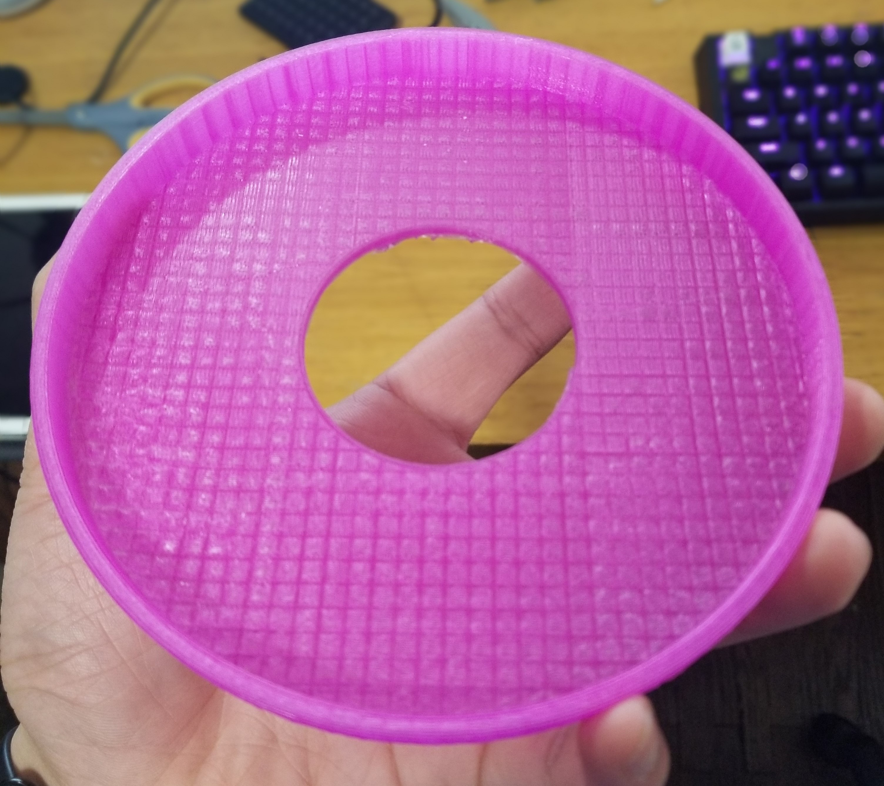
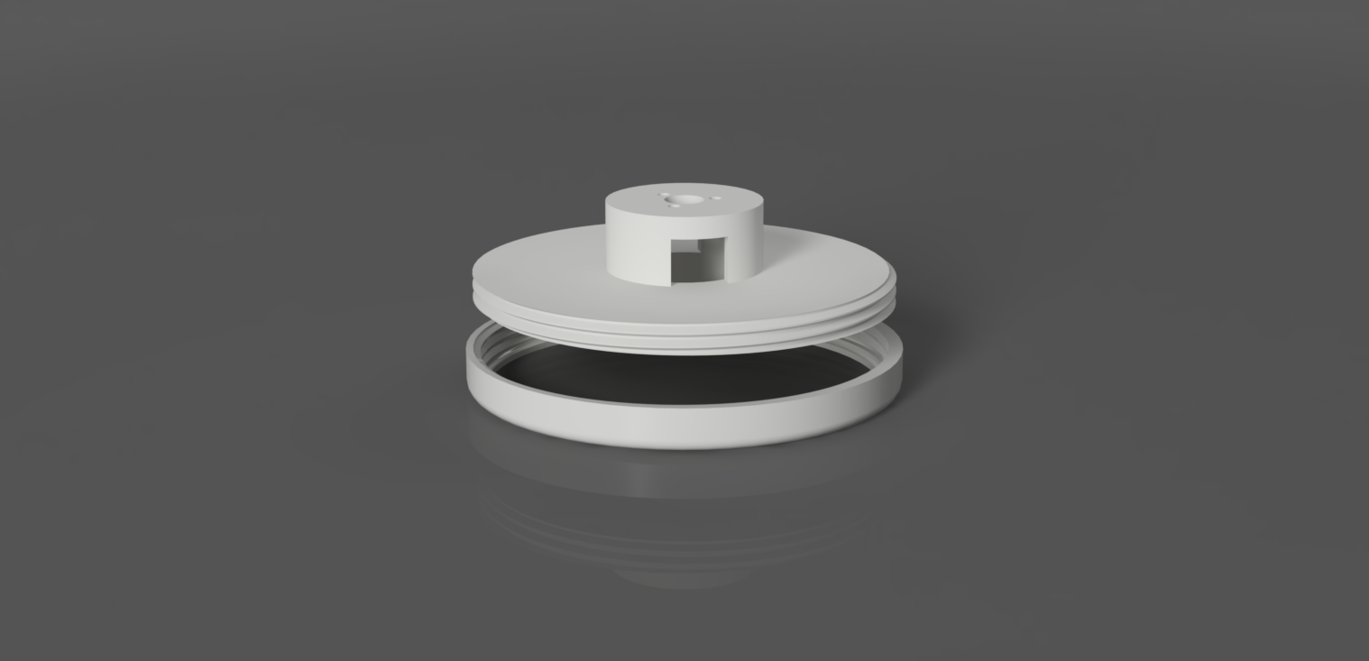
Another compromise we had to make was our game object sizes and resolution. We had a 64-dotstar-LED strip with the middle of the strip being the center of the game. That left us with 32 DotStars to draw the game objects. In that 32x32 space (approximately), we needed to draw the jumping dinosaur as well as the fireballs, we had to trade our object resolutions with the number of DotStars we had.

5.Standards and patents

This project or any component we used was not restricted by IEEE, ISO, ANSI, DIN standards either due to safety concerns or interference with others. We did not find any existing patent that uses the same idea of ours. Our project is original work with the exception of the i2cHelper header file from a previous 4670 project. We were inspired by the fan-tastic POV project 2016 to use a box fan because we didn’t have luck with a 12V DC brushless motor. We were also inspired by Google’s dinosaur game, but the game characters and the game logic were completely designed by us.

Program Design

After we successfully assembled and tested our hardware, we started to work on the software. We first learned how DotStar LED works.

Figure 2. DotStar Data Frames

The DotStar LED strip uses SPI without chip-select. It has a start frame and an end frame. The SPI data line sends a start frame, individual LED frames and an end frame. The start frame is indicated by 32 bits of 0s and the end frame is indicated by 32 bits of 1s. Each LED frame has 32 bits, the first 8 bits are set to 0xe0, and the RGB colors each are represented by 8bits. We started our project with Professor Land’s DotStar code. (http://people.ece.cornell.edu/land/courses/ece4760/PIC32/Pixel_Strip/Dotstar/DotStar_test_rgb.c). The first thing we did was to measure the RPM of the fan using the IR sensor and receiver. We used RB3 to be our IR sensor input pin, and each time the IR sensor passed the receiver, it would get back a 1 value. We set up a 32bit-timer using Timer23, and configured it to use 1:1 pre-scaler. The timer would overflow after 10000000 counts. Timer23 was used as a time source for time capture based on an external event. The CPU has 5 input capture unit, and because we were using RB3, the capture unit we needed to use was inputCapture4. InputCapture4 was configured to detect the IC input on every falling edge, and it had a priority of 2. In the ISR associated with the input capture, we wrote a 0 to the timer to clear it. Therefore the biggest value we got when the fan was spinning would be the time it takes for our fan to rotate one revolution. The value we got was 4528302, and as mentioned in the background math section, we were able to know our fan was 530 RPM. The next thing we did was to phase lock the display. We’d like to update the DotStar LED strip 100 times per revolution. To do this, we opened timer4 and associated it with an interrupt. We configured the interrupt that it’s triggered every 458302/100 CPU count (1 update time). Figure 1 in the high-level design section shows what the update looks like. On every interrupt, we updated the DotStar value as desired, and that allowed us to plot anything we wanted on the POV display. After getting phase lock to work, we started to design the dinosaur game. As we discussed in the tradeoff section, our game character sizes and resolutions were limited by the number of DotStar we had. Since our LED holder also covered 6 of our DotStar LEDs, we were down to a 32x29 game area. In this 32x29 area, we planned our game character sizes and these were shown in Figure 3.

Figure 3. Game character planning

Since we wanted to update the LED strip 100 times per revolution, and that implies we have 100 different locations we can draw on the fan, we could set our game object’s location. Figure 4 shows the position (aka, the nth update-index) of each object. Figure5 shows what the game Objects looked on the fan.

Figure 4. Updates of game objects

Figure 5. Game objects on the fan

We hand-drew the dinosuar image and used a red circle as the fireball image. We followed the tutorial available here https://www.instructables.com/id/Converting-Images-to-Flash-Memory-Iconsimages-for-/ to resize and convert these images to 2D arrays of 24-bit RGB values and saved them as head files (dino.h and fire.h). Each image column could be mapped to one update. For example, dino.h file has an 11x11 2D array. Since we decided to put our dinosaur starting at update 25 and ending at update 36, therefore column 0 of the dinosaur mapped to 25 and column 10 of the dinosaur mapped to 36 and the same rule applied to the fireballs. The next step was to program the accelerometer. When the user shakes the fan, the accelerometer should be able to tell and inform the dinosaur to jump. The accelerometer uses i2C. The i2C has two lines, the SDA and the SCL. We used the i2c helper head from a previous project (see i2c.h in References) and modified it to fit our needs. We set our liner accelerometer to have a 1.66khz output rate with high-performance mode enabled and set our anti-aliasing filter bandwidth to be 400Hz. We read the Z-direction value and decided if the reading value was less than 13000, it meant someone has just shaken the fan, and the dinosaur should jump. Since we did not convert the image to polar coordinate and wanted a more interesting jumping effect, our game objects looked bigger when it’s farther away from the center as Figure 6 demonstrates.

Figure 6. Game objects look bigger when they are farther away

In the meantime, we worked on creating the actual game objects (not just the image arrays). We wrote a dinosaur struct and a fireball struct. The dinosaur struct has 3 fields: feet height, xleft position and range. Feet height indicates the current y value of the dinosaur so we could tell how high it jumped; xLeftPos indicates the left-most update index of the dinosaur; the range is the width of the dinosaur. xLeftPos+range gives the end update index of the dinosaur. The fireball struct has an x position value, range, a y position value representing the height of the fireball, and an alive status. At the beginning of the game, we generated the dinosaur and one fireball at update index 89. Then as time progressed, we slowly moved the fireball by 2 pixels per frame. When the fireball has gone 20 pixels ahead, we generated a new fireball at location 89 and so on and so forth. The maximum number of fireballs in the playground is 3. If the dinosaur successfully dodges the fireball, it disappears from the playground. We achieved this by shifting elements in the array down by one and adding a new fireball. If the dinosaur fails to dodge the fireball, the fireball then ‘blends’ the dinosaur. To achieve this, we cleared all the pixels on the strip, and draw a green line with width 5 and that looked like a ‘blended’ dinosaur. Lastly, we added 2 buttons to the game. One button was the ‘start-game’ button, and the other was the ‘reset-game’ button. Before the ‘start-game’ button is pressed, the LED strip displays Bruce’s colorful DotStar test code. The game starts when the button is pressed. The reset button resumes the game after the dinosaur is dead, so the user can play the game repeatedly without pressing the reset button on the PIC board.

Hardware Design

Hardware Design

Our final design incorporates 3D printed parts and a 0.5m DotStar LED strip reinforced by a ¼” thick basswood stick all mounted onto the front of a 20” box fan. There are two custom printed components. The base is a thin ring meant to sit around the perimeter of the induction motor’s plastic housing. Inside it uses ISO Metric profile M135x4 threads. The mounting piece that screws into it from the top uses the same threads to match and contains screw holes for our 300RPM 6-wire slip ring for mounting through the top cylinder. As explained later in our results section, we found that our slip ring to be our most liable component for failure. Right beneath that mounting point is a two way opening for our basswood stick and our LED strip. Coming through the top of the slip ring, we routed our 6 wires to the side of our box fan, slightly elevated above to the assembly to prevent any wires from catching on the spinning blades. We then assembled our game display with the box fan rotated 90° counterclockwise, taking advantage of the box fan’s handle for gameplay use whenever the user needed to shake the fan. In this position, the user could activate the fan using the speed controller on the left-hand side and then with our push buttons mounted on the opposite side of the fan, use their right hand to start and reset the game. Alongside the top of the fan, we have the remaining key components including our 74125PC level shifter, a SparkFun 6 Degrees of Freedom (DOF) LSM6DS3 sensor, our assembled PIC32 Small Dev Board, and two power supplies: 4xAA batteries in series (6V) and a 9V battery. The AAs power our LEDs and the 9V powers our PIC32. Lastly, there is a QSE114 IR phototransistor mounted on top aimed downward to detect a 940nm IR LED attached to one end of our wooden beam, allowing us the ability to measure the RPM of the fan and phase-lock our display image. All of our components are either soldered together or connected through pins and everything is mounted in place using electrical tape or hot glue. The 3D printed base uses rubber cement and hot glue to keep it in place.

Figure 7. Mounted Base with Threads

DotStar LEDs and the POV Display

As we found out during the design process of this Persistence of Vision display, it can be quite tough to construct a quality one from scratch. With a project budget of $125 and limited knowledge on how to construct a large rotating POV display, we did quite a bit of research on possible solutions for our project. After about 2.5 weeks of designing, we finally came upon a strong enough solution to display our game. Choosing to use Adafruit’s DotStar LEDs was a simple choice as they have individually addressable LEDs and are advertised as having “extremely fast data and PWM rates, suitable for persistence-of-vision displays.” Mounting them was the difficulty though. We first went through several different attempts before we settled upon a solid final hardware design. In our first attempt, we first started by experimenting with an extra brushless DC motor fan in Bruce’s lab. We sawed of the fan blades and tested an initial 3D print design that would sit on top and hold our assembly together. Notably, not only did we find it difficult to balance the pieces onto the motor due to the moment of inertia from rotations, we also were uncertain about the ability to create a strong and safe design that would be reliable enough for testing.

Figure 8. First Attempt with BLDC Motor

With this difficulty, we chose to pivot into using a large 20” box fan which would surely be more stable and resistant to shaking and any additional weights. Our mounting parts were all designed in Fusion 360 and then printed in the Cornell Maker Lab. The design of the box fan provided us with a durable frame from which we had the surface area to mount additional parts. The limiting factors were our means of speed control and the methods in which we could mount our DotStar Strip. In an effort to keep as many pieces as stationary as possible we looked into incorporating a slip ring to handle the wiring that would normally tangle and tension when spun. The goal of the build was to only mount the DotStar strip onto the fan and then have the majority of the circuitry attached to the frame of the fan, allowing for an easy to balance fan. To connect to the rotating DotStars, we would need to pass four wires from the PIC32 through a slip ring: Vdd, Clock Out, Data Out, and Ground. These wires are required for SPI communication to the DotStars. We first ran our wires from the PIC32 through a level shifter to boost our logic levels to 5V as required by the DotStars since the PIC32 is only capable of outputting 3.3V logic. Additionally, we incorporated a 150μF decoupling capacitor across power and ground to help stabilize our signal. The specific wiring can be seen at the bottom in Appendix C. When starting with the box fan, it took us two attempts to get the fit for our mount just right. Due to John’s inexperience with designing in Fusion 360 and 3D printing, we didn’t properly include the necessary threads in our first print and found that our print suffered from some warping by trying to make our base piece fit with all of the curvature of the fan’s center mound.

Figure 9. Initial Design for Box Fan Base

As can be seen from the photo in Figure 7 above, the fan has a round top, meaning that making good use of the surface would be somewhat difficult. To solve the issues of the first print, we remeasured and ultimately found that we could have a stable enough base for our upper mounting piece with just a thin ring like base that only sat around the perimeter. These new parts were printed with a more rigid plastic to prevent warping. The purpose of the upper mounting piece was to allow for flexibility in the design if we found that we need to replace wires or if we needed a redesign for the upper platform. As described in the results sections, we found this to be invaluable to fixing up our project when issues occurred.

Figure 10. Final Mounting Design

Lastly, in order to properly keep our game display oriented, we chose to use an IR emitter and phototransistor together to detect whenever our LED strip had made a full 360° rotation. The phototransitor is wired in a common collector configuration. This gave us the ability to define a zero position for starting our animation. Originally, we had tried doing this switching using a hall effect sensor and a magnet, but we had ordered parts ineffective for the job during the first two attempts. It is very much possible to accomplish this task using a unipolar hall effect sensor switch and a magnet, but we ended up using IR instead as our first sensor was not good for determining switching motions and our second one had too slow of a switching time.

User Controls

For our gameplay features, we have included 2 push buttons and SparkFun’s LSM6DS3 breakout board, a 6DOF accelerometer and gyroscope combo sensor. For our game though, we chose not to incorporate any gyroscope data. To start up the game, the user should start by setting the fan to speed 1. The game starts when the user presses the red button. After dying to a fireball, the user can then press the blue button to start a new life with the dinosaur. By shaking the fan up vertically, we trigger a threshold for jumping and animate our dinosaur with a jumping motion. The buttons are wired with pull down resistors, designed to trigger when the user presses a button and sends a 3.3V signal to one of the PIC32’s input pins. The IMU is wired up in I2C format, using SCL and SDA lines in addition to 3.3V and ground. We used additional 3kΩ pull up resistors for proper communcation to the PIC. When we found our sensor among Bruce’s other spare parts, the device was already soldered to address 0x6B, so we chose to use that.

Figure 11. Main Circuitry

Results

Results

Animation

At about 530 RPM or 8.83 rev/sec, the fan’s refresh rate would not be considered very fast with regards to modern gaming standards. Usually at this frame rate, people can see apparent stuttering as if an image was teleporting across the display. From our tests though, it appears that to the human eye, the persistence of vision effect is significant enough for users to easily focus on the dinosaur as it jumps and each of the fireballs as they move across the display. From the perspective of a camera shooting at the display in video format, we can see the individual LEDs of the DotStar as they rotate as opposed to a picture. This is because most shooting modes will capture frames at 24fps or greater. Contrast this with a photo taken with an exposure time of about 1/10s, and we can see the full image plus a little overlap. If a photo is taken for exactly the period of a rotation, then we should theoretically see a full image without any missing parts or overlap. But since humans don’t process images, but rather motion, we must ask the question of why our game still looks fluid and playable.

Figure 12. Picture with 1/10s Shutter Speed

To determine if a game is playable, the minimum criterion should be sufficient enough response times such that the player is able to consistently respond to events. Since our dinosaur and fireballs are all animated to be moving across the screen, the user is expected to avoid a fireball by shaking fan right before the dinosaur comes into contact with one. In our testing, we have found this to be possible with reliable consistency. Looking closely, it is also possible to notice flickering for each of the animated objects. While it may only minorly distract from the gameplay, it is this very flickering that allows for one to perceive motion in between revolutions despite the lengthy periods. A technique called black frame insertion gives the ability for a user to instead interpolate images in between frames. So instead of seeing jittery motion, the user sees a sort of motion blur at the cost of additional flickering. For us, this is naturally achieved through the spinning of the blades. The result is a sort of holographic effect with the display floating as the user is able to focus on both the lights and the background behind. An example of black frame insertion can be seen using Blur Busters UFO Motion Tests.

Concurrency

The most time sensitive parts of this project relate to the two ISRs that we chose to use in our code. They both relate to displaying a phase locked image of our dinosaur. The first interrupt is based on a high input capture triggered whenever the fan blade makes a full revolution. The second interrupt occurs on a predesignated timer that allows for 100 DotStar updates every revolution when the fan speed is set to 1. While the first interrupt relies on fan speed. The second could very easily be tweaked to occur more frequently for additional resolution or for properly animating at higher RPM. We determined the 100 updates/rev to be sufficient for our animation, but given that each DotStar only requires about 2μs to activate through SPI, we would only require about 128μs to change the color on all of our 64 LEDs. At our current rate, we give ourselves about 1ms in between updates meaning that there is room for speed improvements. In our extra time though, we run extra threads to compute our dinosaur gameplay, check for accelerometer updates, button presses. At bootup, the main priority is animating pretty colors with the help of Bruce’s DotStar test code.

Accuracy

Our device appears to be accurately phase locked with the help of our IR sensor. There is no noticeable shifting in images, with the exception of purposefully animated images.

Safety

We maintained safety by securely gluing down our moving components and taping additional areas to check for any loosening during the spinning. Notably, with our final assembly on the box fan, we found that all of our pieces had stayed in place and seemed to be reliably staying on despite spinning at speeds upwards of 530RPM at times. We used zip ties to hold the dotstars onto the wooden beam. And placed our wooden beam inside the plastic with a friction fit. The upper mount was balanced primarily using an additional large capacitor to help even out the weight on both sides. The threads printed onto the plastic allowed for about 3.5 rotations, giving us a tight fit. The base of our DotStar mount was heavily hot glued from both sides with the addition of rubber cement applied to the bottom of the ring. The DotStars were also trimmed from 72 LEDs to 64 LEDs so that our wooden beam could comfortably fit inside our box’s aluminum housing without coming into contact with any of the edges or the users hands.

Interference with other people's designs

This design does not use any forms of wireless communication. We only generate visible light through our LEDs and emit a small 940nm IR wavelength. Other than that, the device still behaves like a box fan and pushes large amounts of air at the user.

Usability

Usability is limited to people with two arms and the ability to comfortably hold the box fan from its sides about a foot away. The box fan stretches about 22” horizontally and weighs about 5-10lbs. It is important that the user keeps it a safe distance away to prevent any injury and from coming in contact with any of the moving parts. Given the nature of the display and its rapidly changing colors, it can be treated like any other visual gaming device. People who are prone to seizures or blackouts triggered by light flashes or patterns should limit their use of the device if at all.

Figure 13. Active Gameplay

Conclusions

Conclusions

In conclusion, our design project met our expectations. It was the result of us turning what we thought would be cool to an actual running end-application. There are a few things we’d like to do differently if we are going to build another POV game project and there are a few things we’d like to improve on. We could use a box fan to start as opposed to using a DC brushless motor because a small, high-speeding spinning base will not be stable for a game console. In addition, we’d like to improve on our 3D printed threads. Moreover, we think it will be good for us to program more games, and add a game menu to the POV project. Considering intellectual property, we reused the i2c header file from a previous ECE4760 project for our accelerometer reading. The idea of using a box fan after we failed with the DC brushless motor was also inspired by a previous ECE4760 project. However our work still contained a significant amount of original work as the majority work of the project were the 3D print design to keep the LED strip stable as well as the game structure and game code design. This project might be patentable because this project is a good arm exercise tool as one needs to shake the fan to play the game. It could be used possibly as a medical device for children and keep them entertained. We strictly followed the IEEE Code of Ethics. Our project is ethical and healthy to the public (the idea of keeping the user entertained while exercising), and our project is environmental friendly as we used household items and reused many existing parts from the lab. We took valuable advice from the professor, the TAs and our classmates and improved our project based on the suggestions. Our project received some concerns on safety because the game was built on an open box fan. We agree that’s a potential issue, but the fan blades were plastic and it spins at a very low speed. It is hard for one to hurt him/herself as one has to put both hands on the box of the fan to play the game, but it’s still possible for one to be curious and decided to put his/her finger through spinning blades. If we had more time, we would add a plastic cover to the box fan and make it safer. We do not have legal considerations. As a summary, we were happy to see our idea come to life in approximately 5 weeks. It was a fun project and we have learned a lot from it.

Figure 14. Final Build

Appendix

Appendix

Appendix A Online Use

The group approves this report for inclusion on the course website.
The group approves the video for inclusion on the course youtube channel.

Appendix B Commented Code

Our code is publicly available on git. Click to see more! Dino Game

Appendix C Schematics

Figure C.1. Wiring Diagram

Appendix D Cost List

The total cost of this project was $98.51 not including tax and shipping. With a total budget of $125, our project was well within the budget.

Description Part # Vendor Price
1 x Lasko 20” Box Fan B20801 Bed Bath & Beyond $29.99
1 x ECE4760 Small Board n/a Bruce's Lab $4
1 x PIC32 microcontroller PIC32MX250F128B Bruce's Lab $5
1 x Microstick n/a Bruce's Lab $1
1 x 0.5m DotStar LED strip - White 144 LED/m ID: 2329 Adafruit (Bruce's Lab) $24.95
1 x Comidox Slip Ring CP164 Amazon $7.79
1 x 74125PC Level Shifter 74125PC Texas Instruments (Bruce's Lab) $0.81
1 x Basswood stick ¼” x 1⁄2” x 24” n/a Cornell Store $1.69
1 x IR Phototransistor QSE114-ND DigiKey $0.71
1 x 940nm IR LED (IR333C) IR333C/H0/L10 DigiKey $0.47
1 x SparkFun 6 Degrees of Freedom Breakout - LSM6DS3 LSM6DS3 SparkFun (Bruce's Lab) $10.95
3D Printed Parts Custom Built Maker Lab Free
2 x Small Solder Board n/a Bruce's Lab $2 ($1.00/piece)
1 x 9V Battery n/a n/a $2
4 x 1.5V Battery n/a n/a $2 ($0.50/piece)
30 x Jumper Cables n/a Bruce's Lab $3 ($0.10/piece)
23 x Header Sockets n/a Bruce's Lab $1.15 ($0.05/piece)
2 x Buttons n/a Bruce's Lab $1 ($0.5/piece)
Total $98.51

Appendix E Task Distribution

Our team worked closely with one another and it was hard to list specific tasks for individuals. But if we have to divide the tasks, our project can be divided into 2 parts. John was the primary hardware designer while Zesun assisted the hardware assembly; Zesun was the primary software designer while John assisted the design and debugging. For the report, we splitted parts and worked separately. John was the primary website developer.

Zesun Yang John Ly
Game Design and Coding CAD design and 3D Printing
I2C Accelerometer Soldering and Component Assembly
Debugging Mathematical Computations
Software Design Hardware Design

Appendix F References

1. i2c helper.h
2. Image resizing and conversion
3. Bruce’s DotStar code
4. LSM6DS3 data sheet
5. Infrared Phototransistor data sheet
6. Infrared LED data sheet
7. DotStar LED strip data sheet
1 x 74125PC Level Shifter data sheet
8. Phototransistor Wiring

>