The Control Glove
Accelerometer
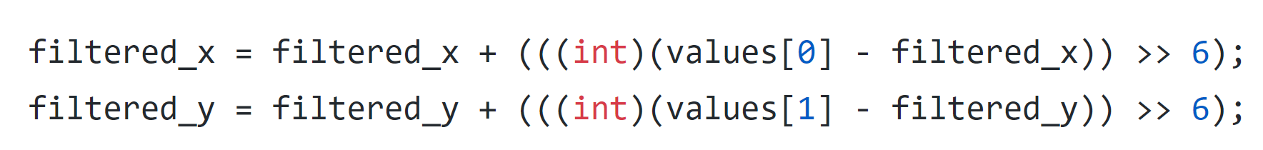
The MPU-6050 accelerometer we used communicates with the PIC over i2c. We fortunately discovered a previous ECE 4760 project (3DOF Stewart Platform) that used the same accelerometer we had, so we were able to adopt part of their code to read the accelerometer data. Their code contained several helper functions such as i2c_read, which enabled us to read various registers containing the data we wanted. The accelerometer values were updated in a thread that ran every 1ms. This was also where we calculated the values being sent to the motors. Initially, we were having problems with jitter, since the accelerometer readings were sensitive and fluctuated quite significantly. To address this, we created filter_x and filter_y variables, which low-passed the readings. We then used the filtered readings to create a direct mapping between the accelerometer values and pwm signal.
Finger Sensors
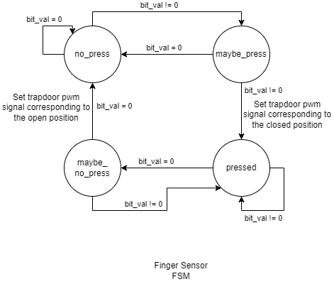
For the finger sensors, we cut up a perfboard into 5 pieces (one for each finger) to be used as contact plates. The plate on the thumb is connected to 3.3V and the plates on the other fingers are conencted to an input pin. These sensors essentially behaved as buttons, where connecting the plate on a finger to the plate on the thumb closed a switch and pulled the voltage on the pin high. The four inputs were connected to pins 0-3 on Port Y. In order to address problems regarding debouncing, we implemented a thread to poll the state of each pin every 30ms (determined by human reaction speed) and utilized a button FSM for each input. bit_val is the value of one of four pins on the port expander corresponding to the specific finger we want to check.
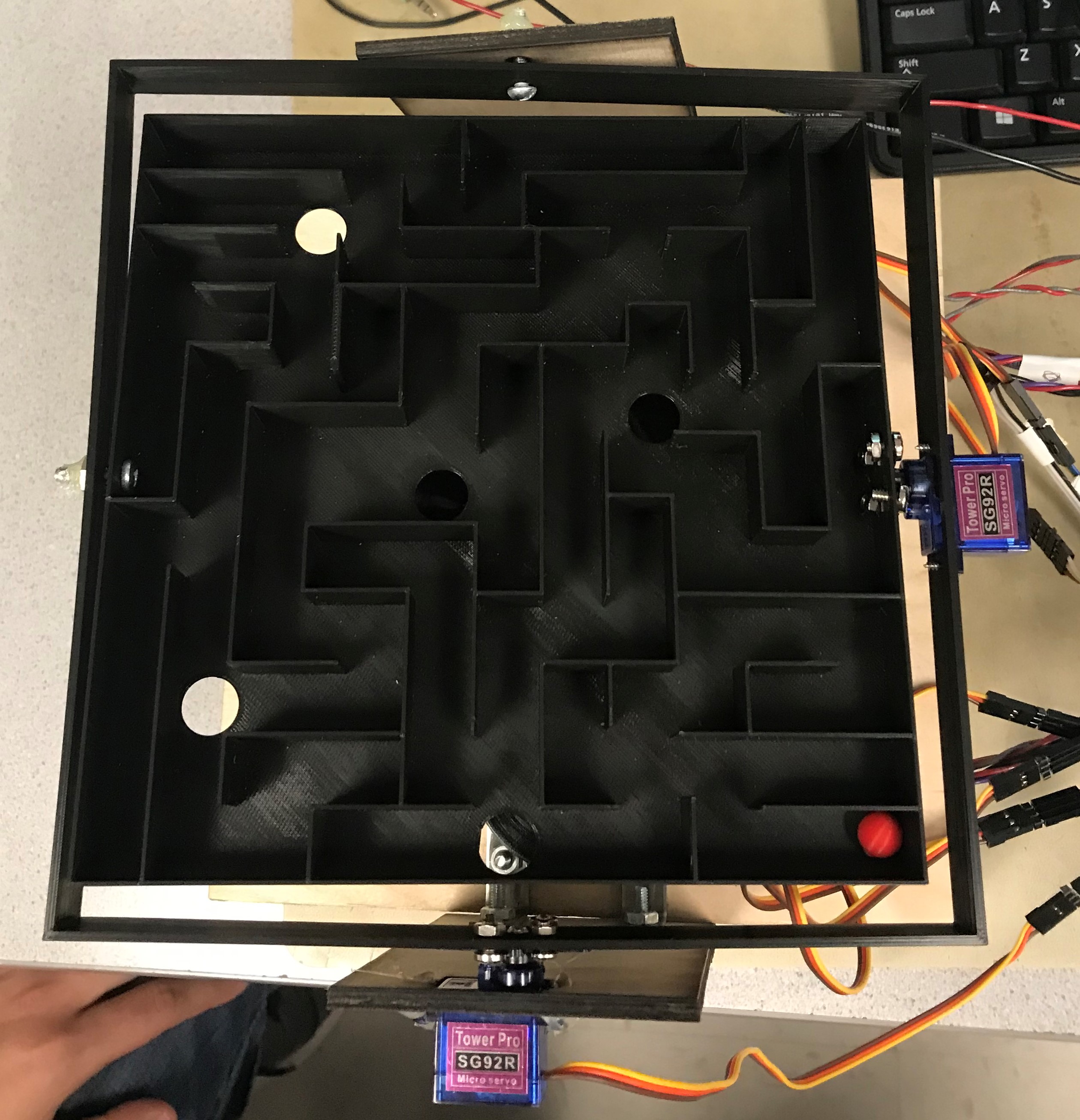
The Maze
Physical Structure
The physical structure of our maze was made out of both 3D printed (from PLA plastic) and laser cut (from 1/8 inch birch wood) pieces, which we designed ourselves in Autodesk Fusion 360. We 3D printed the intricate parts that would be difficult to laser cut or assemble from laser cut pieces, such as the cones, servo doors, and maze itself. We laser cut the large and more basic parts that would take a 3D printer too long to print or would exceed the bed size of the 3D printer, such as the base for our maze. The CAD files (in STL and DXF formats) can be found in the Appendix page of this website.
Servos
The servos are controlled using PWM, which we implemented using output-compare peripherals on the PIC. We configured the output-compares to PWM mode, then connected them to timer2 and mapped them to different pins on the PIC. Then, in the ISR for timer2, which generated an interrupt every 1 millisecond (44,000 clock cycles), we wrote the updated pwm values, which were calculated in the accelerometer thread. We used a timer interrupt instead of a regular thread because we wanted to update the PWM duty cycles at precise intervals.
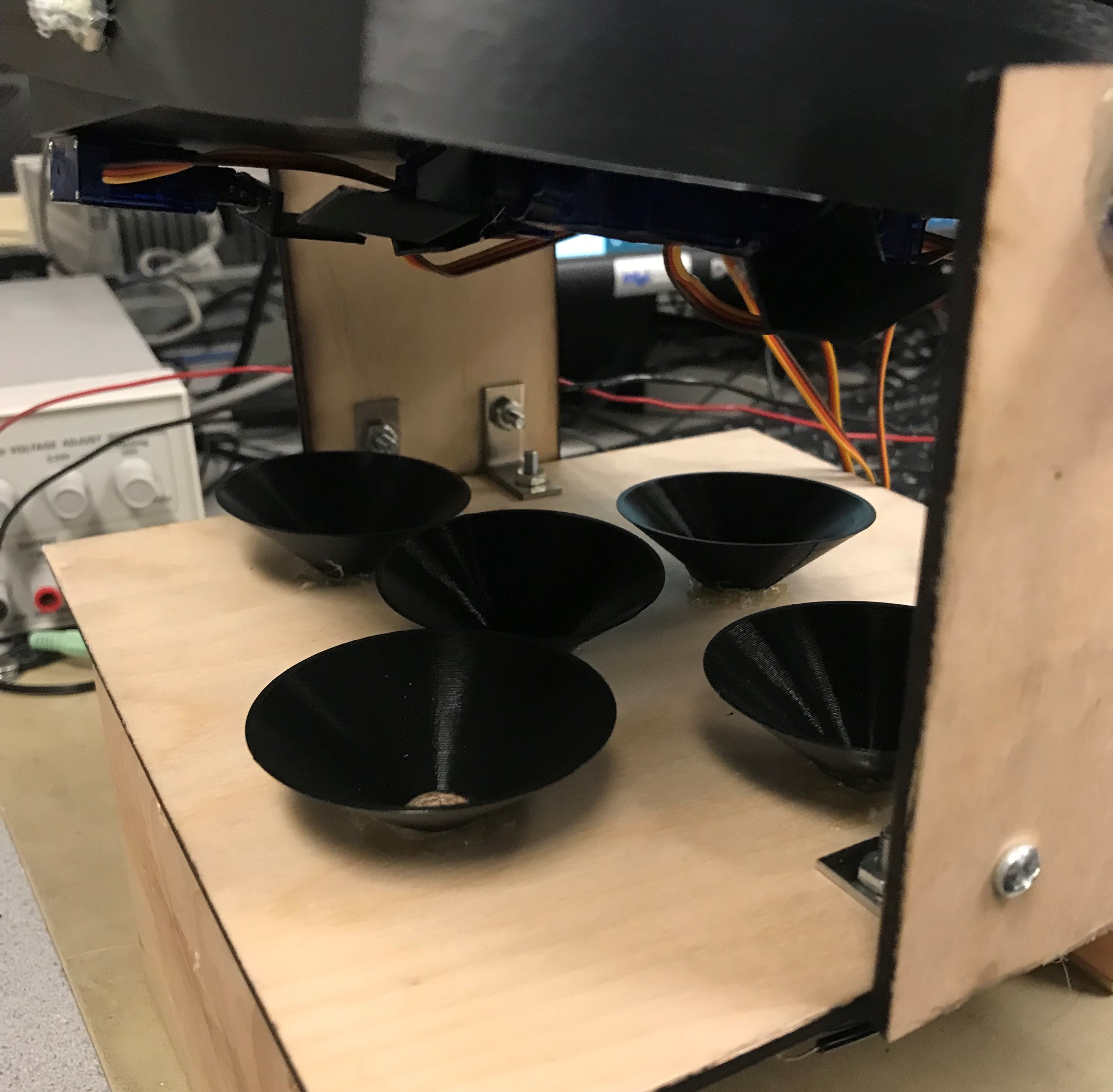
For our game, we needed to control a total of seven servos; two for the tilt of the maze and five for the trap doors. However, the PIC only has five output-compare peripherals and each unique pwm signal requires its own. To get around this issue, we noted that the five servos for the trap doors will never need to move at the same time (due to the way in which we designed the game). This meant that we could output one pwm signal from the PIC, connect it to the COM OUT/IN pin of a demultiplexer, and use three additional pins for the demux select signal (labeled A, B and C in the diagram). Based on the select signal, the demux would send this pwm signal to one of the five servos.
IR sensors
To implement ball detection, we placed an IR LED on one side of each hole, and an IR receiver diode in series with a resistor that goes to ground. A signal pin connected to the PIC is placed between the diode and resistor. The resistance of the IR receiver diode changes depending on whether it detects infrared light (high when no IR is detected and low when it is detected). When the ball falls through it momentarily prevents the light from reaching the sensor, causing the diode resistance to greatly increase and making voltage drop across the resistor change from 3.08V to about 0.2V. We found that a higher resistance value for the resistor in series with the IR receiver allowed for a higher change in voltage across it, which is why we replaced our original design using 330 Ohms with 1 kOhms.
The IR signal inputs are connected to pins 0-4 on Port Z of the port expander, where we configured interrupts for each of these five pins. In order to trigger an interrupt on the PIC, we attached an external interrupt to RPA2, the PIC pin that communicates with Port Z. However, this means that the ISR will be entered upon a change in value on any of the port expander pins with interrupts enabled, without a direct way of determining which specific pin caused the interrupt. To solve this issue, we added a function that reads the Port Z interrupt capture register (which stores the state of the port when the interrupt was triggered) so that we could compare the new port values to the previous ones and determine which one changed. Then, based on the value of the destination hole, we set a win_round flag which is used in the after_round game state to display the appropriate message.
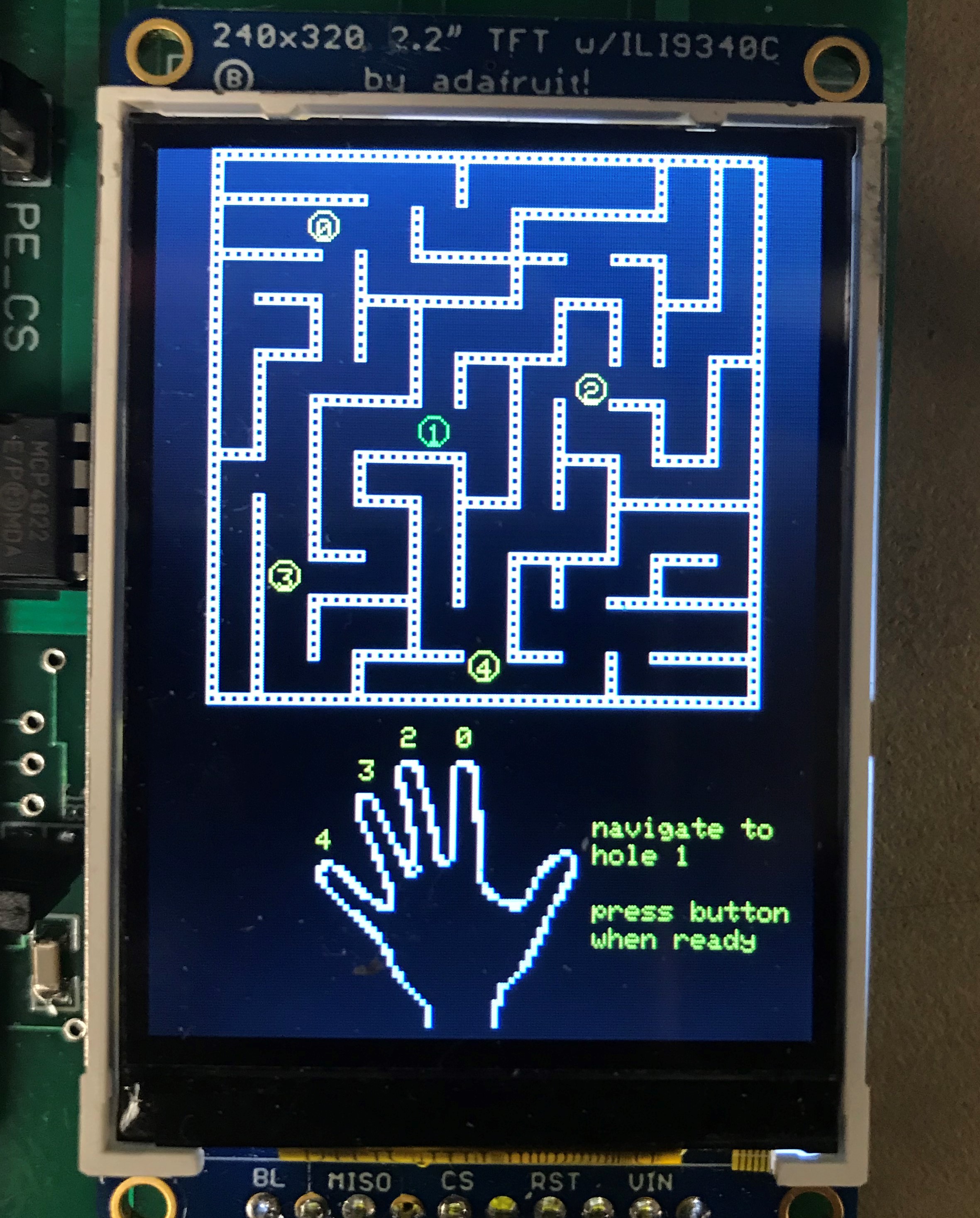
TFT Display
To display the images on the TFT, we first converted our images to bitmaps using this website, then rewrote the tft_drawBitmap function in the tft graphics source file to draw rectangles for each pixel in the image. The size of this rectangle was passed in as a parameter so we could decide how much we wanted to scale the image by. Though it is rather slow to loop through each element in a bitmap and draw a rectangle for each pixel, we decided that this was an acceptable sacrifice due to the fact that we only need to print everything once. This means that it will not interfere with the timing of the game, since after the thread runs at the beginning, it is not scheduled again until the start of the next round.
Program Design
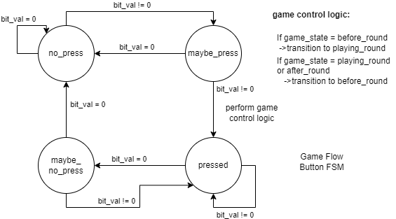
To control the game flow, we created a game state enum consisting of before_round, playing_round and after_round. We included a button in our circuit that, when pressed, would change the game state depending on the current game state, as illustrated in the figure below. To generate a random number for the destination, we utilized the ADC to generate a random seed. This involved taking two readings from a floating pin and summing them together, with the first reading left shifted by one and the second left shifted by 5. We then were able to call the rand() function and receive different random numbers upon resetting the PIC. To get a number between 0 and 4, we computed the randomized number mod 5. Using this number, we were able to create a direct mapping between each finger and the remaining doors.