Program/Hardware Design
Hardware Design
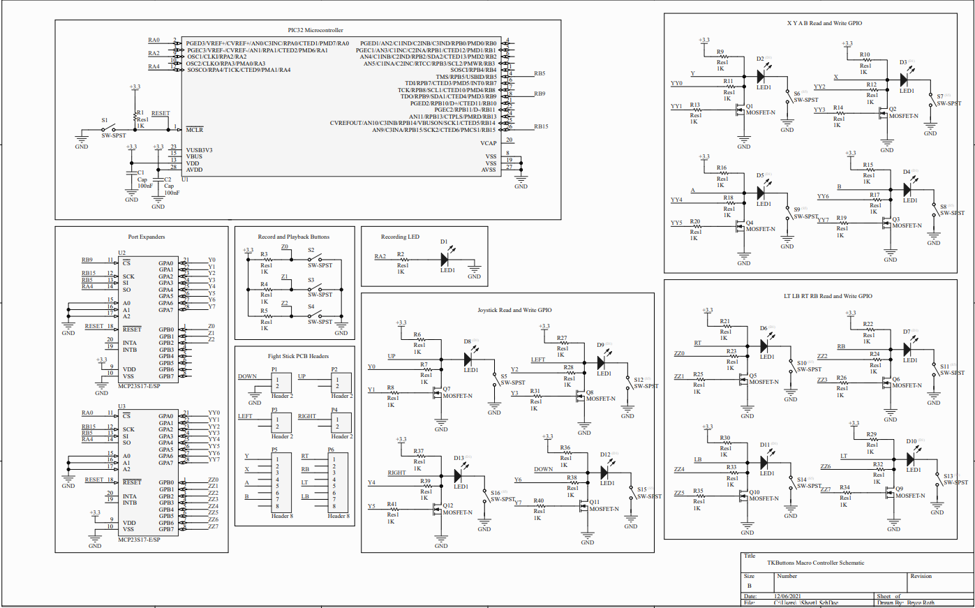
The hardware of our final project is designed to enable the PIC32 to read the button inputs, spoof the button so that the button appears pressed to the PCB onboard the arcade stick, and so that all circuits leading back to the PIC32 are electrically protected. Our project is responsible for controlling 12 buttons related to gameplay, as well as reading three buttons to control recording and playback. To illustrate how all 12 of the button control circuits work, we will examine the data path of one of them.
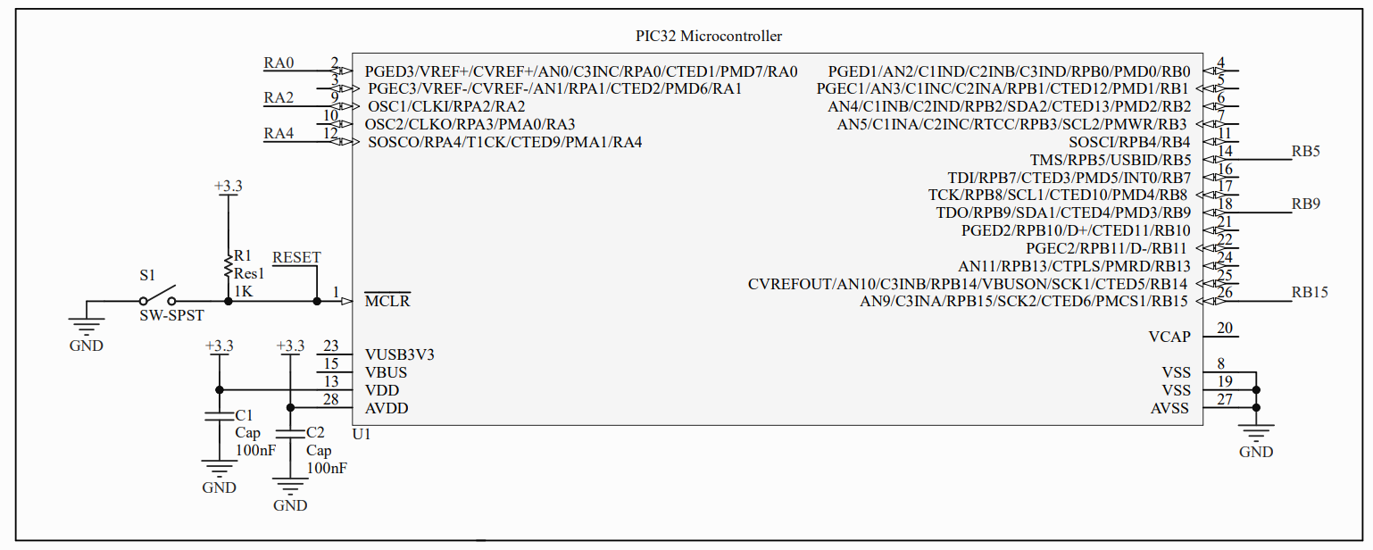
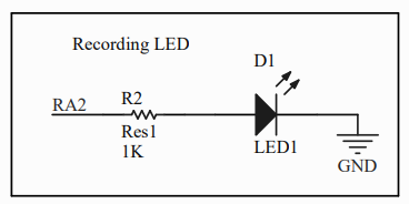
The signals interfacing with the buttons originate from the PIC32 over a single SPI channel. The software onboard uses SPI to communicate with two port expanders which we use to communicate with all buttons on board. RB15 is SCK, RB5 is MOSI, and RA4 is MISO. The chip selects are RB9 for port expander 1 and RA0 for port expander 2. The final connected pinout is RA2, which is used to control the recording LED. The recording LED illuminates when the software is recording inputs. No other headers on the PIC32 are connected other than the necessary power, ground, and reset button.
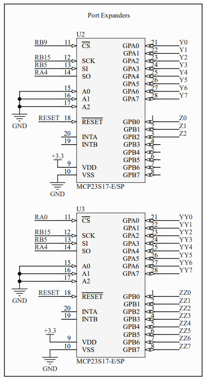
The SPI channel is responsible for interfacing with two port expanders. Each button on the arcade stick receives two GPIO pins: one for reading the button state (input), and one for controlling if the button is electrically pressed or not (output). Since we have 12 buttons, we need 24 GPIO pins in addition to the three record/playback control buttons, bringing the total to 27 GPIO pins. The PIC32 is unable to accommodate so many GPIO pins, so external port expanders are required. Each port expander has 2 ports of 8 pins, so we decided to use two port expanders to have 32 available pins to use, of which we use 27. The reset of the port expander is tied together with that of the PIC32, and the configuration pins are all grounded as they are on the big board from class. The interrupt pins are not connected since the software uses polling to check the buttons. Each pair of GPIO pins, for example Y0 and Y1, are responsible for controlling a single button. Even numbers (0, 2, 4, 6) are inputs, and odd numbers (1, 3, 5, 7) are outputs. Using this GPIO scheme we were able to mitigate confusion during the wiring process.
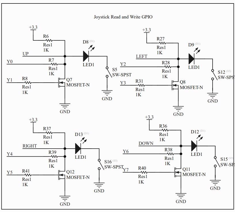
Figure 4 shows the circuitry for the joystick’s GPIO. This circuit is duplicated twice: once for the XYAB GPIO, and one for the LT LB RT RB GPIO. Thus, we have 12 button control circuits total. Each button is represented by an SPST switch. When the button is pressed, both the GPIO input from the port expander and the input from the PCB read low. Otherwise, the circuit is connected to a 3.3V pullup so they read high. This matches the hardware on the arcade stick. When the button is pressed, an indicator LED also lights up to confirm that the button is registered as pressed. The second GPIO from the port expander is an output and is connected to the gate of an n-channel MOSFET. When the output is set high, the MOSFET allows current to flow through and forces the node at the drain to be electrically low. This can be read on the port expander and PCB. In addition, this turns the LED on as well. As a result the LED in each circuit is extremely useful for debugging.
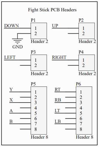
On the arcade stick, each button has two inputs, one of which is pulled up. The ground of one of these inputs is connected to the PIC32 ground so that the PCB logic highs and lows can be manipulated by the PIC32. The rest are not connected for simplicity. The arcade stick inputs are connected to the corresponding node of the GPIO inputs from the port expander.
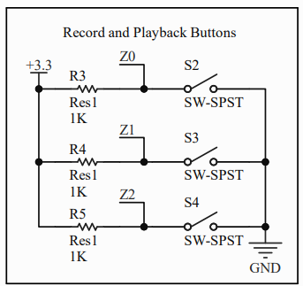
The record and playback control buttons are onboard the arcade stick on a separate PCB. The wires from the PCB header we are concerned with are the three logic wires pulled high responsible for reading each button, and a single ground wire. The logic wires are spliced so that they can be plugged into the port expanders for reading.
When all components work in tandem, the software is not only able to control the outputs of each button and read the state of each button, but also able to receive input from the user to determine whether a combo should be recorded or played back.
Software Design
The software is designed to record a single combo and the timing of the inputs, as well as play the combos back with said timing. The program is split into four parts: the setup, the read button thread, the record/playback control thread, and the write button thread. The setup occurs at the top of the program file and inside the main file.
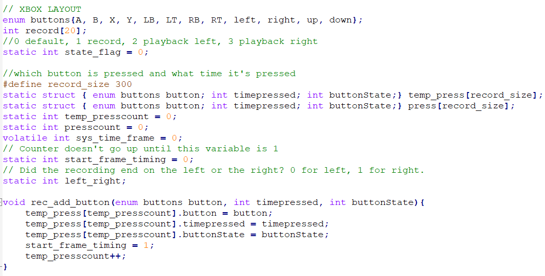
Before understanding how any other thread works, we must discuss the format in which button presses are stored and played back. When the PIC32 is recording button presses, each button press and release is stored inside the temp_press array, which is copied to the press array at the end of the recording. Each element of the array is a struct consisting of three data values: the button pressed, the time pressed, and the “edge” of the button press (high or low). The button pressed is stored as a “buttons” enum, each value of which is representative of one of the arcade stick’s buttons. These include the eight buttons for attacking (X, Y, A, B, LT, LB, RT, RB), as well as the four joystick cardinal directions (up, down, left, right). Since the joystick hardware consists of four limit switches, we do not have to work at all with ADCs in our project and can treat the joystick as a set of four buttons. The timepressed stores the time at which the button was pressed. This time is updated using the PIC32’s timer module, which causes an interrupt at a speed of 120 frames per second. The start_frame_timing variable will control whether the sys_time_frame variable (the system time) will be updated in the ISR.
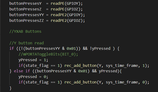
The protothread_key thread focuses on reading the button presses and adding it to the temp_press. We have define multiple variables which will track the state of each button on the arcade stick (X,Y,A,B, etc). Additionally, we defined the buttonPressesY, buttonPressesYY, buttonPressesZ, buttonPressesZZ variables, which will store the value returned after reading the first and second port expanders. The thread will check if the pin corresponding to the button is set (checking if the correct bit is set to zero) and if the specific button has not been pressed. If this condition is true, then the input is added to the temp_press array. If the exact opposite condition is true, the input will still be added, but with the buttonState argument set as a 0. This indicates that the button was released (negative edge) instead of pressed (positive edge).
The protothread_record thread defines behavior of the record and playback buttons. We first need to read port Z of the port expander as those are connected to the record, playback left and playback right buttons. Next, we check if the record button has been pressed with a very similar approach to the one used in figure 8, except this time, an LED will light up to indicate that we are recording, whereas pressing the record button again will turn off the LED. If we are currently in record mode and we press the left playback button, our code will record all the buttons inputted between those two events and will set a flag which indicated if the left playback button has been pressed. This will clear the record flag. Next, if we are not in record mode and we press the left playback button again, we will go into playback mode, where we playback all the inputs recorded, and directional inputs are reversed depending on whether the player is on the left or right side of the screen. This logic is repeated for the right playback button as well.
Finally, the protothread_playback thread will playback the inputs stored in the temp_press array. We first check if we are in playback left or playback right mode, then we check if the system time is zero. If this is true, we save the previous set of inputs and outputs to and from the port expander. If we also observe that the previous input is not the same as the current input, we write all zeros to the port expanders. This is to cancel any recording in progress. Afterwads, we check the array of inputs to be played back, and make use of a switch case statement to write specific numbers corresponding to the pressed button to the port expander. This will "press" a button on the arcade stick, thus playing back all buttons pressed.