DESIGN
High Level Design
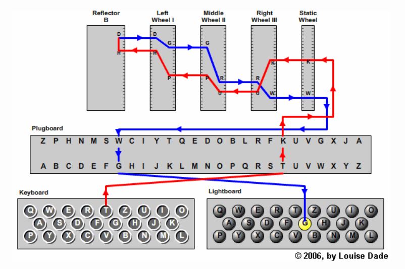
As for the encryption logic, our project simulates the actual enigma machine’s encryption logic. Our Enigma machine supports the English alphabet only, with no special characters. The components of the Enigma machine are as follows:
- Rotors: We have 3 rotors whose wiring specifications follow those used by the 1930 Enigma I: Rotor I (EKMFLGDQVZNTOWYHXUSPAIBRCJ), Rotor II (AJDKSIRUXBLHWTMCQGZNPYFVOE), Rotor III (BDFHJLCPRTXVZNYEIWGAKMUSQO). From each of the configuration above, we can define a function w such that w(i) = j, with i being the index of the letter in the configuration and j being the index of the letter in the alphabet. Each rotor has a left side and right side. If the current enters the rotor from the right side at contact i, it leaves the rotor from the left side at contact w(i). Conversely, if the current enters the rotor from the left side at contact j, it leaves the rotor at contact the w-1(j). The rotors behave according to the following rules: just before each letter is enciphered, the rightmost rotor always steps; just before each letter is enciphered, if the top letter of any rotor is its turnover, then that rotor and the rotor to its left step (this rule does not apply to the leftmost rotor); no rotors step more than once per letter enciphered. We define that the turnover of Rotor I is Q, of Rotor II is E, and of Rotor III is V.
- Reflector: We also have a reflector, which is simpler than rotors as it does not rotate and we do not have to worry about left-to-right or right-to-left since in the original Enigma machine, the current only flows in one direction for the reflector. Our reflector configuration is YRUHQSLDPXNGOKMIEBFZCWVJAT
- Plugboard: For the plugboard, we implemented it in software. The role of a plugboard is simply to swap pairs of letters.
Below is the diagram showing the internals of the Enigma machine.
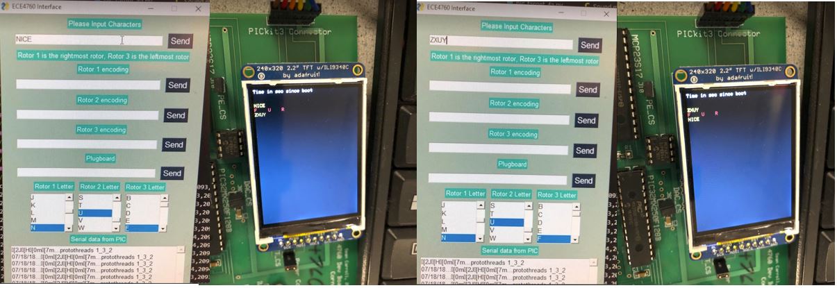
In addition, we also make a user interface that allows users to input the configuration, the initial offset of each rotor, and the plugboard configuration. When the encryption is output to the TFT display, there will be a sound effect following each letter output.
We also wire a rotary encoder which comes with a knob to our circuit. The knob can also act as a push button. By turning the knob of the encoder, users will be able to change the initial offset of each rotor. By pushing the button, users can choose which rotor to change its offset. When the users rotate the knob, there is also a sound effect associated to each incremental rotation. The logic of the encoder is as follows: The output signals are displaced at 90 degrees out of phase from each other and if the encoder is rotating clockwise, output A will be ahead of output B and vice versa. This can be demonstrated from the diagram below.
As for the sound effect, we used the sound of a typewriter from the following YouTube video:
Our project meets all the IEEE standards.
Program Design
We start off by creating a Python GUI which allows users to input the string they want to encrypt, change the rotors’ initial offsets, and input the configurations of the rotors and the plugboard. We use the PySimpleGUI package for the GUI. We first open the microcontroller serial port then define the layout of the GUI. For the input text, we use a text box for the input string and a send button that the user can click on when they are sure that they want to send the message. For the rotors’ initial offsets, we make 3 list boxes for 3 rotors, each with letters from A to Z. For the configurations of the rotors, we use 3 text boxes with 3 send buttons. In our C program, we make a function called uppercase_convert which loops through every character in a string and returns a string with the same letters but in uppercase. We make this function to process input strings so that the results will always be in uppercase. We implement a string input thread to process the input string that is supposed to be encrypted, the rotor configurations and the plugboard, a list box thread to process the 3 list boxes for the 3 rotors for their initial offsets, and a Python serial thread. If we detect an input for the plugboard inside the string input thread, we will call the function initialize_plugboard to initialize the plugboard according to the users’ input.
We then move on to implement the encryption logic of the Enigma machine. We declare a volatile array of 3 elements called rotor_offsets containing the index of the 3 rotor offsets and an array of 3 elements containing the index of the turnovers. We also declare a 2D array for the 3 rotor configurations and an array for reflector configuration. We write a function called char_to_index, which takes a letter in type char and returns the index of that letter in the alphabet by subtracting ‘A’ from the character. We then implement a function called rotor_r_to_l which takes in the index of the contact point from the right side and the rotor number and returns the appropriate index that is supposed to leave the left side. We also have a function called index_inverse which, given the rotor number and an index, will output the value of the inverse mapping of that index. After that, we implement a function called rotor_l_to_r which takes in the index of the contact point from the left side and the rotor number and returns the appropriate index that is supposed to leave the right side. We then write a function called reflect which takes in an index and outputs the reflected index from the reflector configuration. We also have a function called plug_swap to implement the swapping logic of the plugboard. Finally, we piece all the components together. We implement a thread called PT_Encrypt. Inside the thread, we then make a while loop to loop through all the character in the input string (in uppercase), make a variable called res, assign res with the result from calling the function plug_swap on the index of the input character. We then call spin_rotors. We then assign res to the values in this order: rotor_r_to_l(res, 0) → rotor_r_to_l(res, 1) → rotor_r_to_l(res, 2) → reflect(res) → rotor_l_to_r(res, 2) → rotor_l_to_r(res, 1) → rotor_l_to_r(res, 0). We then add res to ‘A’ to obtain the encryption result.
For the rotary encoder, we make a thread for it. We declare the following global variables: A_in_last (the last output read from A), A_in (the current output read from A), B_in (the current output read from B), button_last (the last output read from the button), button (the current output read from the button), and counter (which is incremented every time we detect a button push, which is used to determine which rotor to change the initial offset). The output A is read from RB7, output B is read from RB8, and the button push output is read from RB13. Inside the thread, we first read RB7 and assign the output to A_in_last in binary, and read RB13 and assign the output to button_last in binary. If button is 0 and button_last is 1, a button push is detected, we increment the counter and assign the counter with counter modulo the number of rotors (in our case it is 3). We then read RB7 and assign the output to A_in in binary. If A_in is 0 and A_in_last is 1, we read RB8 and assign the output to B_in. If B_in is different from A_in, indicating we are rotating the knob clockwise, then we increment rotor_offsets[counter]; else we decrement it. If rotor_offsets[counter] is less than 0, we assign it to 25. We also assign rotor_offsets[counter] to rotor_offsets[counter] % 26. Finally, we assign A_in to A_in_last and button to button_last.
As for the sound effect, we download a YouTube video that has the sound of a typewriter. We then use a sound editing software called Audacity to trim off the part of the video we need and download it as an mp3 file. We then use MatLab to read the audio file and copy the output array onto our C program as an array called sound. In the C program, we declare a variable called note_time as a counter variable which is incremented every time we enter the Timer 2 interrupt service routine. To make a sound every single time we rotate the knob, we set note_time to 0 every time we call the function spin_rotors. To make a sound for every character output, we set note_time to 0 in the encoder protothread whenever we detect the encoder rotating. Inside the interrupt service routine, we set the output of channel A of the DAC to sound[note_time] and channel B to 0. Inside the main function, we set up the DAC and the timer interrupt.
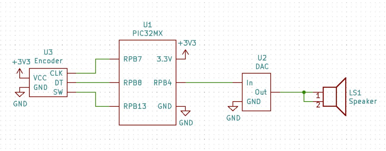
Hardware Design
Below is the schematic of our circuit. Other than the PIC32, our circuit includes a rotary encoder, an audio socket, and a speaker.