The Ultimate Alarm Clock
Hardware Design
Creating the timebase The AT90S8535 chip features an onboard RTC (real-time clock). The timing for it is kept by an external crystal oscillator, running at 32.768 KHz. The crystal is hooked into pins 6 and 7 of Port C as shown in the schematics.Two 12.5 pF capacitors are placed from the sides of the crystal to ground. As described in the software section, the Timer 2 interrupt is set to a prescale of 128. As the crystal oscillates at 32768 cycles in a second, a prescale of 128 would have exactly 32768/128 or 256 pulses per second. With the 8 bit Timer 2 set to interrupt on overflow, an interrupt occurs precisely every second, triggering the software routine for incrementing the time/date.
LED Display Driving The LED display is a multiplexed, common anode display designed for individual addressing of each digital. All of the segments in each digit each have a unique anode, and all of the segments (A-G) have unique cathodes. The display is addressed by the CPU through an 8 bit command. The upper 4 bits are an active low addressing of the desired digit. The most significant bit corresponds to the left-most digit. The rest of the binary codes for the digits can be seen in the table.
| Digit (from left) | Binary Code |
| 1 | 0111 |
| 2 | 1011 |
| 3 | 1101 |
| 4 | 1110 |
The actual digit displayed is decoded by a National Semiconductor 7446 chip. The 7446/7 chips receive a 4-bit binary coded decimal value and convert it into a 7 segment display code. The output is active-low, thereby grounding the pins which should be on and driving those which should be off. For this reason, the common anode design display was chosen. The BCD input is sent in the lower 4 bits of the Port B output. By using the upper 4 bits for digit selection and the lower 4 bits for the actual value, each digit in the display can be individually addressed and displayed. The software strobes the display, switching digits every 4 milliseconds. At this rate, the human eye perceives all of the digits as on constantly and does not see flicker.
One problem encountered in the implementation of the display was the dimness of the digits. They were barely visible to the human eye. The problem was that the upper pins of Port B could not supply enough currently to properly drive the LEDs.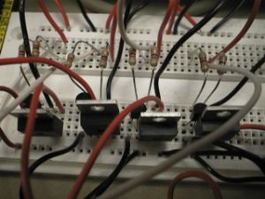 TIP31C Power transistors were used, driving the LEDs with the board's Vcc (5 volts). However, the board couldn't supply enough current (20 mA) to all of the LEDs, and the port pins couldn't drive the power transistors fully. The solution was two-fold. First of all, 2N3904 transistors were hooked in a darlington configuration to maximize the current through the LEDs. Once in this configuration, the LEDs could be hooked to the collector of the power transistor. Secondly, the voltage was increased from 5V, to 9V,and eventually to 12V. Due to the high frequency of the strobing, series resistance wasn't even needed at 12V, but a nominal resistance of 100 ohms was used for minimal protection.
LCD Display & Keypad
 The LCD display hookup was fairly straightforward. We had used the same display before, and it merely required hooking up the data lines directly to Port D, and connecting the power and ground. The 10k potentiometer above the LCD controls contrast and the exact hookup can be seen in the schematics.
The keypad was also fairly straightforward, being hooked up directly to Port A. By driving the upper fourlines as outputs and the side lines and inputs, and then reversing the two, the keypad can derive a unique keycode for each of the 16 keys on the pad. The main hardware design consideration is the charging time for the pins for scanning, which is roughly equal to 1 microsecond. In this case, the charging time is handled by the program which executes 4 NOPs when switching between inputs and outputs.
The Alarm
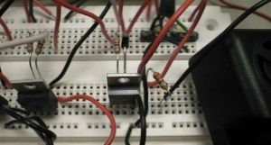 The alarm is triggered by a TIP31C, driven directly from pin 0 of Port C. The alarm is a self-contained module, powered by the 12 volt supply. A diode protects the transistor (not really necessary here, but was a throwback to when the TIP31C dropped a relay closed instead of directly driving the alarm. It is kept just for safety.) A series resistor was also thrown in the circuit just to make the alarm sound less painful. The module was quite deafening to hear, and with the transistor and resistor, the sound is more annoying and less painful.


Webpage created by Joel Avrunin ('01) and Philip Weiss ('00).
Created May 4, 2000. Last updated May 6, 2000.