Introduction
For our final project, we wanted to do something robotics because we thought it would be cool. Originally, we planned to build a robotic pet dog but it was deemed to be mechanically too hard. So we undertook a robotic arm project instead. Since a project on robotic arm was done last year, we wanted to take a different approach. Our project plan was to be able to train the arm to do something and have it repeat the movement automatically. The movement was also to be optimized in software so that it tries to use best path possible between two points.

High-level Design
Operation mode
There are three modes of operation that we provide:
![]() Normal mode:
the arm can be controlled manually to any position desired.
Normal mode:
the arm can be controlled manually to any position desired.
![]() Training mode:
the arm can also be controlled manually as desired except the movements that
you make will be recorded and optimized for playback. This mode is obtained by a push-pull button.
Training mode:
the arm can also be controlled manually as desired except the movements that
you make will be recorded and optimized for playback. This mode is obtained by a push-pull button.
![]() Playback mode:
the arm will automatically move from one point to another with the data
obtained from the previous training session. If no training was done, the arm
will not move. While the arm is in this
mode, change of mode is blocked and prohibited.
Playback mode:
the arm will automatically move from one point to another with the data
obtained from the previous training session. If no training was done, the arm
will not move. While the arm is in this
mode, change of mode is blocked and prohibited.
Interaction with the arm
The manual control of the arm is provided by the control box that came with the arm except that the connections from the control box go through the microcontroller which controls the outputs to a series of switches that turn on/off /switch direction of the arm’s gear motors. The mode of operation is provided by a push-pull button and a push button. When the push-pull button is off and the push button is not pressed, the arm is in normal mode. When the push-pull button is on, the arm is in training mode and when the push button is pressed, the arm is in playback mode. The arm automatically reverts to normal mode after it has finished executing the trained motion.
Sensors input
Wrist
photosensor
 We
wanted to take a different approach in sensing the robot arm’s environment to
last year’s project, so we originally planned to use hall-effect sensors to
detect arm’s movement. These hall-effect
sensors seemed ideal in that no mechanical connection between the sensors and
the magnet are required, hence it should give pretty high accuracy and
robustness. But, we encountered a lot of
problems such as small distance range of detection and difficult to implement a
rotational movement detection scheme.
After two weeks of perseverance to no avail we finally gave up and
decided to look for something else to use.
We
wanted to take a different approach in sensing the robot arm’s environment to
last year’s project, so we originally planned to use hall-effect sensors to
detect arm’s movement. These hall-effect
sensors seemed ideal in that no mechanical connection between the sensors and
the magnet are required, hence it should give pretty high accuracy and
robustness. But, we encountered a lot of
problems such as small distance range of detection and difficult to implement a
rotational movement detection scheme.
After two weeks of perseverance to no avail we finally gave up and
decided to look for something else to use.
We found the potentiometer scheme to be pretty robust in detecting angled
movement from shoulder, elbow and gripper and phototransistor sensors to
be ideal in detecting rotational movement from the base and wrist.
Software design
We divided our program into several tasks:
![]() void scan (void) – This task scans the input from the manual
control box and record the buttons and the directions that were pressed. The operation mode is also determined by this
function from the input buttons.
void scan (void) – This task scans the input from the manual
control box and record the buttons and the directions that were pressed. The operation mode is also determined by this
function from the input buttons.
![]() void output (void)
– This task outputs to the reed relay switches that control the gear motors to
make appropriate arm movement.
void output (void)
– This task outputs to the reed relay switches that control the gear motors to
make appropriate arm movement.
![]() int performConversion(int) – This task converts
the input voltage from the selected potentiometer and return the digital value.
int performConversion(int) – This task converts
the input voltage from the selected potentiometer and return the digital value.
![]() void record(void)
– This task records the motion sensors input while in training mode. This means recording the initial voltage
reading (by calling performConversion)
for gripper, elbow and shoulder sensors and counting pulses detected by
the phototransistors for wrist and base.
void record(void)
– This task records the motion sensors input while in training mode. This means recording the initial voltage
reading (by calling performConversion)
for gripper, elbow and shoulder sensors and counting pulses detected by
the phototransistors for wrist and base.
![]() void recordFinal(void)
–This task records the final voltage readings for gripper, elbow and shoulder
sensors at the point when the mode returns from training mode to normal mode.
void recordFinal(void)
–This task records the final voltage readings for gripper, elbow and shoulder
sensors at the point when the mode returns from training mode to normal mode.
![]() void play(void)
– This task playback the data in the most recent training session. It blocks access to other mode until the
movements have finished executing.
void play(void)
– This task playback the data in the most recent training session. It blocks access to other mode until the
movements have finished executing.
The main loop continually calls the scan function at a predefined interval. It then checks what mode it is in. If it is in normal mode, it just output to the motor whatever input was scanned in by calling the output function. If it is in training mode, it also additionally calls the record function to track the movement. The recordFinal function is also called when it detects a change in mode from training to normal. Lastly, if it is in replay mode, it playbacks the movement by calling the play function.
Hardware design
This is a high level block diagram of our hardware. Click on each block to get the schematic for that block.
For port assignments, see the header comments in our code.
`
Result of design
 Our
goals were to train our robotic arm to pick up an object and move it from
A-to-B. We initially set milestones, so
we could know of a weekly basis on how we are making progress towards the final
result. Our second milestone involved
working with the sensors since that was a crucial part of the project.
Our
goals were to train our robotic arm to pick up an object and move it from
A-to-B. We initially set milestones, so
we could know of a weekly basis on how we are making progress towards the final
result. Our second milestone involved
working with the sensors since that was a crucial part of the project.
 Usability
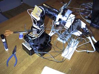
The project still needs more tweaking before it can be fully functional. This includes soldering the connections so that the wires don’t hamper the arm’s movement, and tailor the code such that the arm will move to an object position and then end position.
Speed & Accuracy
Speed is not a problem for this project hence we did not pay much attention to it. Accuracy for the sensors differs between the potentiometers and the phototransistors. The potentiometers proved to be very accurate while the phototransistors were only as accurate as the width of one flap used to trigger the phototransistors on and off.
Problems encountered
 Failing
potentiometers, it works one day, and then it’s dead. Re-soldering it isn’t a problem, just an
annoyance.
Failing
potentiometers, it works one day, and then it’s dead. Re-soldering it isn’t a problem, just an
annoyance.
A failed Reed relay, we found that one blew out, and we didn’t have a replacement. This is okay since we could reallocate a reed relay from the shoulder since its motor burned out on Friday, which of course as Jon put it, ’what a bummer!’.
As of Sunday (or Monday morning) before our demo, the arm
movements by itself successfully remember its training. Simultaneous movements are also okay. We’re hoping our demo is okay. We still need to make some adjustments to our
code, so we’ll do it 9am, before we have to demo at
Next time
Sign up for a Thursday or Friday lab session. So for those of you who’re taking 476 in 2002 or beyond, it might be a good idea to be in a later lab section. =)
Although a certain person claims that Monday groups have 4 extra days to start the project, face it, it’s really the last week/days that things really get done and when final testing is done….
Of course, if we had more time to test, yea, that’d be great, but I guess we’re pretty happy with what we accomplished.
Listing
Materials
![]() AT90S8535 with 8 ADCs (only 3 were used)
AT90S8535 with 8 ADCs (only 3 were used)
![]() 5 V reed relays (10)
5 V reed relays (10)
![]() potentiometers as angle sensors (3)
potentiometers as angle sensors (3)
![]() phototransistors as rotation sensors (2)
phototransistors as rotation sensors (2)
![]() 10k ohm resistors (2), 5k ohm resistors (4), 1k
ohm resistors (4)
10k ohm resistors (2), 5k ohm resistors (4), 1k
ohm resistors (4)
![]() a push-pull button
a push-pull button
![]() a push button
a push button
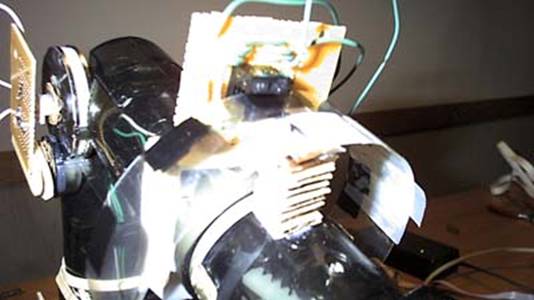
![]() An OWI 007 robot arm from Jameco
An OWI 007 robot arm from Jameco
Code
Download controller.c
Schematics
The connections to each of the gear motors inside the robot arm looks like the diagram below. The two switches are implemented by the reed relays which are controlled by the microcontroller. The software makes sure that at most only one of the switches below for each motor are turned on at a time.

Two reed relays are needed to implement the two switches to control the motor output above:
 When
the microcontroller turns on one switch by grounding the line, the other microcontroller
turns off the switch by setting the line to Vdd.
When
the microcontroller turns on one switch by grounding the line, the other microcontroller
turns off the switch by setting the line to Vdd.
In this way the gear motor is only connected to the motor’s positive supply or negative supply at one time.
The other side of the motor is connected to both positive and negative supply hence the direction of the motor is reversed by just controlling these two switches.
The control box contains a series of two-way mechanical switches for each movement.
Each switch looks like:

The direction of the switch is determined using similar pull-up resistor technique as in scanning a keypad. First, note that the two end-points of the switch, A and B, are shared between all switches and they are originally connected to Vdd and Gnd so that when the switch is pressed, a direction connection from Vdd or Gnd to the middle point, which were originally connected to the motor output, is formed. With all connections to the microcontroller, we can scan the direction of switch as follows:
- Set the output pins from the microcontroller to the end points A and B to Vdd and Gnd respectively.
- Set the pin connected to midpoint as input and turn on the pull-up resistor and wait for the resistor to charge up.
- If a ‘1’ is detected on the mid-point then we know that button B was not pressed. Otherwise, the direction is B.
- Repeat 1 and 2 but swap Vdd and Gnd on A and B.
- If a ‘1’ is detected on the mid-point then we know that button A was not pressed. Otherwise, the direction is A.
The phototransistors are used to detect rotational movements. Two phototransistors are needed to determine the direction of that the movement is rotating. These are connected to microcontroller as follows:

The mechanical flaps are spaced out so that each flap covers both transistors totally and each spacing uncovers both A and B completely. This is done so that only one of the two transistors A, B can switch state at a time.
The distance of the rotational movement is determined by the number of pulses that pass through the phototransistors. The direction is determined by the current state of the two phototransistors and the next state that they are in. These are summarized as follows:
|
|
Next state |
Current Direction |
|
A = off, B = off |
A = on, B = off |
Right |
|
|
A = off, B = on |
Left |
|
A = on, B = on |
A = on, B = off |
Left |
|
|
A = off, B = on |
Right |
|
A = on, B = off |
A = off, B = off |
Left |
|
|
A = on, B = on |
Right |
|
A = off, B = on |
A = off, B = off |
Right |
|
|
A = on, B = on |
Left |
‘Off’ means covered
(transistor off), and ‘on’ means uncovered (transistor on). Direction is in reference to the diagram above
and is the direction of that the mechanical flap is moving.
The potentiometer connections are Vdd and Gnd to each of the pole while the output is connected to microcontroller ADC. The knob on the potentiometer determines the angle position for the joint that it is mounted on.
Special thanks
![]()
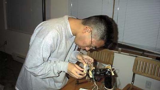
![]() TA Jon Winslow for tips and suggestions for
mounting the sensors
TA Jon Winslow for tips and suggestions for
mounting the sensors
![]() Hideomi Nihira for loaning us his digital
camera!
Hideomi Nihira for loaning us his digital
camera!
(Here’s a picture of him)