
By: Alex Cerruti and Chris Wherry
EE476 -- Spring 2002
Introduction
The first club/disco lights that flashed to the beat of the music
were invented in about 1968. A
set of lamps would flash to 3 different frequency ranges: one set in
sync with the bass signal, one with the treble, and a last set in sync
with the highs. Only
transistors and thyristors and extensive analog circuits existed back
then to control the lamps. It
was later determined that this many flashing lights was confusing, and
had no correlation to the dance music, hence it was quickly adopted that
many lights could flash in sequence or in patterns only to the bass
channel (or the beat of the music, which is what people usually dance
to). From this point on, a
whole class of club lights and various effects were created:
rotating oil wheels that projected multiple psychedelic patterns
on the floors and walls, pin spots flashing in random sequences and
colors, scanners which sweep in various directions, helicopters which
spin, dichro flowers that produced spinning colors to the beat of the
music, and so on.
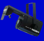
Finally in 1990 Intelligent Lighting was created using the magic of silicon chips. They all work on the same principal: a beam of light is sent through a colored filter and a shape (Gobo). The beam is then projected onto a motorized mirror, which allowed the beam to be arbitrarily pointed. The beams would change color and directions based on the beat, or on a preprogrammed sequence using DMX-512 (see below for links and a discussion). Our club light is a variant one of these original Intelligent Lights.
The original owner of this club light was trying to
fix it when he accidentally shorted out the original controller to 120
VAC. It was not surprising
when nothing worked after that! The
original board contained an Atmel 8051C chipset that performed the main
functions (including DMX). The
rest of the board was actually constructed using rather awful
engineering techniques. For
example, the stepper-motor for the color wheel was powered off of an
unregulated DC voltage (immediately after full-wave rectification).
That is to say, the 12-volt stepper motor was running off of a
highly unstable 24 volt supply! It
was no surprise the motor was overheating with the original circuit.
Certainly, better circuit design was needed.
Anyhow, we decided that we needed to revive this light and get it working again. Since no schematics and no information at all can be found on the workings of the light, we decided to take it upon ourselves to redesign the entire analog to digital interfaces to the microchip. Furthermore, all the software for controlling the stepper motors (to obtain random colors), the lamp, and the muffin fan had to be created.