|
|
|
|
The following code was developed with CodevisionAVR.My microcontroller program is organized into the following modules: PS/2 KeyboardMost of the information here is referenced from Adam Chapweske's site. In addition to the material on his site, I have added a state machine of my own design, which might be useful for people who want to implement the PS/2 protocol. Most PS/2 keyboards use a 6 pin mini-DIN socket. A good panel mount plug for interfacing with the keyboard can be found at Digikey.com (Digikey no. CP-2660-ND ).
The data and clock lines are pulled-up to 5 volts. We only need to connect 2 I/O pins( with pull-up turned on) of the Atmel MCU to these lines. The transmission of data is synchronous, the keyboard always generates the clock signal unless the computer wants to send a command. There were two ways that I could have monitored the keyboard clock signal
I choose to use the external interrupt pin on the MCU for the keyboard clock so that I would not have to waste precious clock cycles monitoring the keyboard clock line. The PS/2 keyboard protocol can be broken down into keyboard to MCU and MCU to keyboard transmission. The part common to both transmission directions is the keyboard data frame and the clear-to-send signal. The data fram consists of
The number of 1's in the data bits and the parity bits must always be odd. The acknowledge bit is used by the keyboard to acknowledge a computer to keyboard transmission. When the clock line is high, the sender is clear to start transmission. Thus in order to control the transmission of data frames, the computer can pull the clock line down to prevent the keyboard from sending another data frame. Keyboard to Atmel MCU transmissionIn this transmission mode, the keyboard generated all signals. The data should always be read on the falling edge of the clock. Thus, I set the external interrupt 0 line on the Atmel Mega163 was set to trigger on the falling edge of the clock. So that the interrupt service routine would read the data line on each falling edge interrupt and add the data bit to a buffer. When enough bits to form a data frame had been read, the ISR would verify the recieved data. If there were errors, the MCU would send a retransmit command to the keyboard, otherwise the complete byte would be added to a receive buffer. The falling edge interrupt was used for transmissions in both directions and so a direction flag was needed to keep track of which direction the current transmission was in. For more details on the transmission protocol, please refer to Adam's page. Atmel MCU to keyboard transmissionFor MCU to keyboard transmission, the MCU must manipulate the clock and data lines to initiate a data transfer. Hence the external interrupt is always turned off when doing such initiation. For transmission, the MCU must wait until there is no current transmission, with the clock line high and the data line low. Then the following must be done in order:
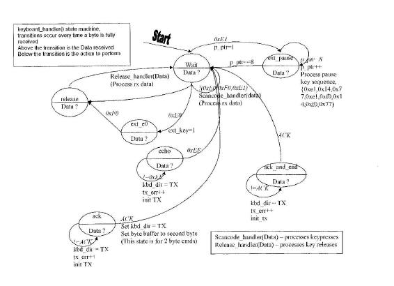
After doing the above, the keyboard will generate a clock signal. The MCU will set the data port on each falling edge interrupt according to the data frame. The keyboard reads the data on the rising edge of the keyboard clock. When the complete data frame has been sent, the MCU checks whether there is any error or any byte left to send. If so, then it initiates another transfer, if not, it sets the direction flag to receive so that on the next falling edge, the MCU would be ready to accept data from the keyboard. State Machine to handle PS/2 Keyboard
Click on the picture above to link to a bigger version. PS/2 keyboard referenceA good PS/2 keyboard reference is Adam Chapweske's site at http://panda.cs.ndsu.nodak.edu/~achapwes/PICmicro/PS2/ps2.htm STV5730AThe STV5730A is a on-screen display IC capable of supporting both NTSC and PAL. The chip is controlled from the MCU via a simple uni-directional serial interface. The only input to the MCU from the STV5730 is the MUTE signal, which tells the MCU whether a NTSC video input is being supplied. STV5730A serial interfaceThere are 3 wires in the serial interface, DATA, CLK and CSN. The protocol is as follows:
Using 1 message format is sufficient. In my project, I implemented both the 16 and 8 bit message formats, however I mostly used the 16 bit format because it is more convenient even though there were redundant bits. The 16 bit message format is as follows:
BUF[11:8] - row address DEPL[4:0] - register address STRU[7:6]
The code for sending messages to the STV5730 is in STV_send_16(), only the 16bit message format was used in my project. The MUTE signal goes high whenever a NTSC signal is detected by the STV5730A on it's video input port. The MCU needs to monitor this signal to switch the STV5730A between video overlay mode and self-generated video signal mode. In order for the text to appear on the video input, the STV5730A must be in overlay mode. If not, there will only be noise on the output port. On the other hand, without an input video signal, the output is unstable unless the STV5730A is in self-generating video mode. There are two functions in STV5730.c for switching the STV5730A between the two modes mentioned above. STV_video_mode() : Overlay mode. STV_full_page_mode() : Self generated NTSC signal mode. More details can be found in the specification sheet for the STV5730A. User InterfaceThe user interface is handled in UI_monitor(), the keyboard buffer is checked using kbd_getch() which either the ASCII code or 0 if no key was pressed. Whenever a key is pressed, the user interface state machine checks that it is in one of the following states and performs the appropriate action:
SensorsThe pressure sensor and ADC inputs are read by executing the sleep command of the MCU. Program execution resumes when the voltage conversion is complete. The temperature sensor digitizes the temperature on-board and the MCU communicates with it via the Dallas Semiconductor 1-wire bus. The library included with CodeVision C has 1-wire bus support. For the 1-wire bus, I needed to first define the port used before including the libary. #asm Before the MCU can read the temperature sensor, it must first initialize the 1-wire bus by calling w1_init() For my project, I only had one device on the 1-wire bus and so did not have to handle the device identifiers for multiple devices. Thus to read the temperature sensor, I only needed to run the following code: temp = ds1820_temperature_10(0);//input arg=0, because
only 1 sensor on bus Conversion of the pressure sensor voltage to the actual pressure is as follows: The pressure sensor can be simplified into the following block diagram from the datasheet.
Where Vfullscale = 4E-3 * Vsupply = 20mV for a supply voltage for the pressure sensor of 5V. However because we are using the INA121 to amplify the pressure sensor voltage before conversion, we need to do the following:
|
|
|