High Level Design
![]()
![]()
Rationale for idea
The idea for the dartboard came from many weeks of discussion at Greek Peak. Many ideas considered would require a tremendous amount of hardware design, an issue that could lead to major setbacks towards the end of the semester. An example: a remote controlled car, which require an analog controller, an RF transmitter and receiver, motor control, and power control. Another example was a model of a plane fitted with microelectricalmechanical (MEM) devices that would detect pressure on the wings and display the pressure readings on a video monitor. This would require the procurement of expensive devices, and the complex incorporation of the force sensors with the model wing. If any aspect of these projects failed, the entire project would fail.
The electronic dartboard would provide a fair amount of hardware design, while incorporating a complex code structure to play games while generating video and polling the dartboard for the hit. The video display was highlighted throughout the semester, and felt should be included in the final project design. On top of this, a dartboard is a fun device to design for, which erased the feeling of doing work during the 75 total combined hours of design and implementation.
Overview
The dartboard has many aspects to the design. The board itself, electronic sensors for score regions, a microcontroller to keep track of game progress and memory of specific games, and an output to the video monitor. A useful aspect of the project is that the project can have different levels of design. Once the basic setup is completed, more games can be added, the video display can be elaborated, and even sounds could be incorporated. On the other hand, if the base project dose not work, the games could be eliminated and the video generation could be replaced by a LCD display. The original list of specifications and functions included in the project proposal are listed below:
Specifications:
| The dartboard will use a standard regulation size face for plastic tipped darts. |
| The dartboard will play as a minimum the game '301'. - Additional games will include 'Cricket, 501, 701, 901, Baseball, Reverse Cricket', and potentially some invented games. |
| The dartboard will be a minimum of 1 player - Additions may include 2, 3, or 4 players. |
| The dartboard will use MEMS force sensors to sense each region, the doubles, triples and bulls-eye region. |
| A video monitor will be used to keep track of score and number
or darts remaining. - Additions will include sounds for dart strike based on certain regions, basic animation, proper cricket display, and menu for possible dart games. |
| The base microcontroller memory will be used - Addition will incorporate larger memory. |
| System must have a reset game command, dart pop out command, and dart miss command. All will require buttons. |
| System will allow for user input for game type and number of players. |
| Microcontroller Functions: | Video Functions: | Dartboard User Enter Functions: |
| Decode region dart hit | Display Menu of games | Select game type |
| Display and process game type | Display menu of # players | Select number of players |
| Calculate game scores | Generate zero visual artifacts | Return to Main menu, reset |
| Display and process each game for specified number of players | Display dart hit region | Delete last dart throw (Bounce-out) |
| Track scoring to each player | Display game play screen, with appropriate graphics | Cycle through players, accounts for dart miss |
| Reset Game |
| Erase last dart entry |
| Cycle through players |
| Video generation |
| Determine Winner |
Background- Timing Considerations
The main issue with the design was the precise timing between dart hit, dartboard polling, video generation, and game play. An overview of the timing is given.
|
Action
|
Time
|
| Dart hit pulse duration | 400 µs - 4000 µs |
| False readings on other regions | 0 µs - 1 ms |
| Time to generate video line | 63.5 µs |
| 10 input lines to poll | 2 µs/poll including delay for voltage charging |
| Total time to poll all input lines | 20 µs |
| 1 Frame update | 1/60 second ~ 16,667 µs |
| Time for game calculations, button polling | 1841.5 µs |
| Button press | 5 - 500 ms |
| Time between dart throws | 4 - 30 seconds |
With this information there are two main issues, dartboard polling while generating video, and refrain from reading a false positive. The dartboard polling was accomplished by eliminating no-ops in the video generation code to produce 2 input polls/line write. This indicates a complete poll of all input lines can be accomplished in 317.5 µs. This is well below the min dart hit pulse duration. For a complete discussion on dartboard polling see Hardware.
The second issue was de-bouncing the dartboard to eliminate a false positive reading. This required a de-bounce hold on reading for 1.27 ms. Close to 90% of all dart hits generated a pulse longer than 2 ms, thus this was a fair de-bounce time. The 1841.5 µs for button polling and game play was an adequate amount of time to read a button press and calculating the game play. There was also a 500 ms period of time in which the dartboard would not poll, providing extra time for game calculations and screen updates. This 500 ms 'turn off' was executed after the microcontroller could identify the hit region. The 500 ms is well below the time between dart throws of 4-30 seconds.
Logical Design Sequence & Structure
The work progression for the dartboard followed this order.
1. Define input-output pressure sensor map.
2. Generate generic video.
3. Detect dart hit and map hit in software.
4. Generate video while polling for dart hit.
5. De-bounce dartboard.
6. Create video graphics for menus and games.
7. Add push buttons.
8. Code for games.
9. Revise code.
10. Make the device standalone.
The steps were carried out in a linear order such that the extra features would be added at the end when the basic functionality was working. If the software could not map the appropriate dart hit region, then the project would have been a bust early on. The steps also allowed for a logical flow of development. For instance, during the decoding of the hit region, it was helpful to have generic video where the dartboard variables could be displayed on the video screen. This also would highlight any potential issues between dart detection and video generation. By having the video and dart polling working, the games could be coded with ease by using the dart as the input and using the video output to see the progress of the game code development.
An overview of the entire setup is shown below. Specifics on hardware and software design can be seen in those sections.
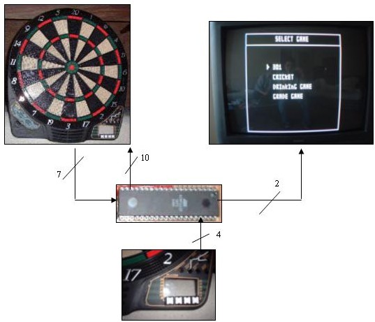
The overall design involves four main components, the pressure sensor dartboard, the Mega 32 microcontroller, 4 push buttons, and the video display. 10 polling inputs are sent to the dartboard, which outputs the polled input signal on 1 of 7 output lines. During this time the microcontroller sends the video signal to the TV. Between the polling and video generation, the microcontroller controls the game play and polls for the push buttons.
Functions Implemented
| Microcontroller can detect region dart hit, including doubles, triples, bulls eye, and double bulls eye |
| Microcontroller can generate video with graphics |
| 4 push buttons for user control to select game, number players, reset, bounce-out, and next player |
| Different video display for each game. |
| 4 Games - Cricket, 301, Drinking Game, & Grade Game |
| Up to 4 players for each game |
| Zero flicker on the video display |
| Standalone design |
| Real time game updates, including dart hit region, score update, and graphic updates |
| Determination of winner |
Hardware/Software Tradoffs
There were three main tradeoffs within the design: display area vs. dart polling, false positive vs. true dart hit, sound vs. pin usage.
Since there wasn't much time before and after the video segment, we had to make a trade-off on the width of the video output. The video generation code by Bruce Land used nop's in the video blast macro to effectively widen the video output. The macro had 8 nop's and was called 16 times per video line. By getting rid of the nop's, we were able to gain 128 clock cycles or 4us at the cost of reducing the video output width by about a third. This was an acceptable trade-off and the best solution to polling for a dart hit.
Since multiple regions can be triggered from a high velocity dart throw, debounced must be implemented to decide a valid hit. We know that a false trigger lasted for at most 1ms. If a region is triggered for more than three complete poll cycles, then we know that that region must be valid. This would require a minimum valid dart detection time to be 1.27ms. Therefore, we cannot detect the shortest dart hit with the tradeoff of not detecting a false positive. The average dart hit was about 2ms, so this method works for 98% of the cases tested. That's why we implemented the bounce out button just in case the user threw the darts very lightly.
Sound could not be added due to the lack input/output pins on the microcontroller. Adding sound would have required sharing a port with last input and output polling pins. It was discovered that by attempting to mask these pins to generate sound would cause errors in the dart detection. Thus, being able to read a dart hit was given priority than generating sound.