 |
| Introduction |
| High Level Design |
| Hardware |
| Software |
| Parts |
| Mechanics |
| Ethics |
| Results/Conclusion |
| Code |
| References |
Hardware

Microphone Amplifier
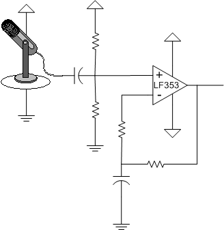
The first step in transmitting sound is to digitize soundwaves. For this we used an electret microphone purchased from Radtronics. Frequent shoppers at Tito's place downtown know that finding spec sheets for products there is impossible. The microphone he sold us had three leads, which after considerable angst we decided were for power, ground, and signal. The signal coming off the mic was far too low to be read (with any degree of precision) by the analog to digital converter. So of course, an amplifier is needed. Before the signal is put through the amplifier however it is first put through a capicitor to remove DC, and then through a voltage divider to appropriately bias the signal. A LF353 op-amp is used to boost the signal, the gain is adjusted by the resistors and for the mystery microphone the gain is around 50-100 (depending on how much popping and how much quality you want).

Laser Driver
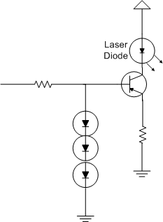
After the A/D converter translates the mic signal into 8 bits, the MCU generates the appropriate bits to send (including start and stop bits) and applies them to the laser driver circuit a 5V and 0V signals. The BJT in this circuit turns on at 5V and provides the proper current according to the diode and resitor values.

Receiver
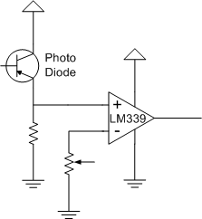
A photo diode detects the laser pulses in a different (distant) location. This signal is put through a comparator in order to generate solid 5V and 0V values which are applied to the receive pin on the microcontroller.

Laser Driver
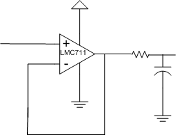
Once the signal is put through the DAC (not shown, it's a simple ladder), it is boosted and low pass filtered (to improve sound quality).