Rationale
Many camera-based security systems today involve the use of multiple cameras placed around a room continuously recording to a central monitoring station. This technique is both wasteful of multiple stationary cameras and captures hours of non-interesting film of an empty, dark room and is very expensive. The Eye in the Sky security system only uses one camera that can slew around a large open space and only records when it is alerted to an intruder.
Structure
With Eye in the Sky security, a room is divided into zones. Each zone has a type of detection sensor, these sensors can be added to the room in a modular fashion so that the system is easily expandable and upgradeable. The sensor types used in the prototype system include Infrared emitter receiver pair light sensors, hall effect magnetic field sensors, and piezo-electric vibration sensors. Typically, hall effect sensors are mounted on a sliding door or on a pivoting doorway. IR sensors are placed across doorways or windows, and vibration sensors are mounted on the floor. Each sensor around the room comprises a security zone.
The microcontroller is alerted to an intruder through an external interrupt signal on INT0 (on a falling edge signal). All of the digital outputs of the sensors are tied to the inputs of an AND gate as well as to the inputs of PORTB pins. An interrupt is generated if any of the sensors are triggered (active low). Once in the external interrupt ISR, the micro then determines which sensor caused the interrupt by examining the port B input pins. Once the triggered sensor is identified, commands are sent to the computer to instruct it where to slew to camera to capture an image.

The location of each of the sensors is stored in SRAM. Sensor positions can be edited by the user as well as new sensors added and their positions assigned. If one of the sensors has been triggered, while the system is disarmed, the user will not be able to arm it. The panel display will give an error message indicating which zone is violated. Before the system can be armed, the zone must be made secure (by closing windows, door, etc.) After entering the arming sequence, the user has a set amount of time to leave the room before the system becomes armed. To disarm the system, the user has a finite amount of time to enter a four digit code in the proper timing sequence. Failure to enter the proper code results in setting off the alarm.
Software/Hardware tradeoffs
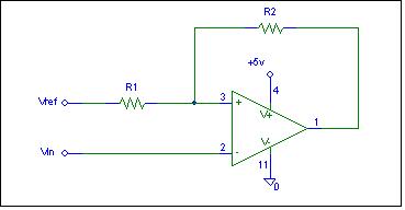
All of the sensor inputs provide an analog signal output with the exception of the Hall effect sensors (which have Schmidtt Triggered outputs). Digitizing these signals could be done in software using the microcontroller's on-board 10 bit A/D converters or in hardware with operational amplifiers. For this discussion we will consider the example of the vibration sensors. The signal from the vibration sensor must be sampled at least 10kHz to accurately capture a vibration. This ADC would have to constantly be running for each of the vibration sensors in the room. If other sensors are added to the system, they will also need to be tied to the ADC and sampled constantly (but perhaps at lower frequencies). An interrupt on analog compare interrupt would have to be set in the event that the digitized value exceeds some threshold value. The drawbacks to this system are numerous. First, the number of sensors is limited to the number of on chip ADC pins (8). And secondly, continually sampling several sensors at reasonably high frequencies consumes a large amount of processor resources. The benefit of a software solution is that no additional parts are necessary making the design less expensive. Using hardware to digitize waveforms from sensors has many benefits. First, it allows for the use of many more than eight sensors in the system. Second, the addition of extra sensors does not require much more of the processor's resources since they are digitized independently from the processor. Third, ADC hardware can be customized to the particular requirements of each type of sensor. And finally, any value of gain can be easily added to signals before they are digitized.
Another prominent tradeoff in this security system is the control of the USB camera. To have the microcontroller send control signals directly to the camera would require an on-board USB driver program and complicated algorithms to package data in the USB format and send it out to the camera. Additionally, snapshots from the camera would consume vast amount of the processor's memory making it not feasible to store more than one or two pictures without moving to external memory. Some microcontrollers have on board USB device handling modules to aid in this control, but the Atmel Mega32 unfortunately does not. The benefit of a camera directly controlled by the MCU is that the system would not have to be tied into a computer system but as we do not have budget to allow for additional external memory, this approach is discarded. By interfacing with a computer via the RS232 standard and having the computer with the proper USB drivers instruct the camera when to take a picture the problem becomes vastly simplified. Additionally, the computer can easily store any number of images on to the hard disk. In the case that this security system gets tied into a central monitoring station, the data can be transmitted serially over a modem to the CPU and images stored there thus not forcing the customer to buy a PC.
Intellectual Property
The USB camera controlling functions used in this project is the property of The Imaging Source. A trial version of their Imaging Control acquisition tool was used in our visual basic GUI to send command to the camera as well as to capture and store images. To use this software in a run time application requires purchasing licenses. The pricing scheme is as follows:
Runtime |
USD |
1 IC Imaging Control runtime license |
69.00 |
10 IC Imaging Control runtime licenses |
490.00 |
25 IC Imaging Control runtime licenses |
990.00 |
50 IC Imaging Control runtime licenses |
1900.00 |
100 IC Imaging Control runtime licenses |
2900.00 |
Unlimited IC Imaging Control runtime licenses |
4900.00 |
For a high volume product, the Eye in the Sky Security Co. would have to purchase the $4900 unlimited license fee.
Our password validation code requires that the user enter a four digit disarm code correctly and in the proper timing intervals. A company called BioNet Systems, LLC has patented ( #4,805,222 ) a similar technology that involves recognizing keyboard keystroke dynamics when entering a code to identify a user. In a paper entitled User Authentication for Keypad-Based Devices Using Keystroke Analysis by Spinnaker International Ltd., it was determined that the use of rhythm in code identification is technically feasible and maybe a very popular practice in the near future. Both the product and study listed above take a biometric approach to user identification; meaning, they work under the premise that everyone develops their own unique natural typing rhythm that can be identified. Our product does not rely on a person's natural typing rhythm, but a planned sequence of button presses that can be synchronized each time with a 2Hz blinking LED. Therefore, our implementation of rhythm sensing may be considered different from the BioNet approach and may, itself be patentable.
Background Mathematics
Shortest Slew Path Calculation
Two stepper motors are used to slew the security camera in elevation and azimuth. Coordinates are stored for each sensor placed around the room. If a sensor triggers while the system is armed, the motor slews to that zone following the shortest path. The stepper motors used in this project are LB82773-M1 2 phase bipolar. They rotate 7.5 degrees per step and thus 48 steps per revolution. The angular position of each motor is encoded with a number between 0 and 47 and stored in the global variables motor_h, and motor_v. The positions of each of the sensors are stored in sensh[n] and sensv[n] where n is the sensor number. For the determination of the shortest motor slewing path, the sensor coordinate is subtracted from the current motor coordinate. If the resulting number is greater than 24 (half a revolution), then the shortest path would be to have the motor rotate the other way. This is accomplished by subtracting 48 from the difference, the negative result indicates the motor will spin the opposite direction. In the case that the difference between the sensor location and the current motor location is less than -24, 48 must be added.
11

Determination of Vibration Epicenter
Theoretically, if the time a vibration reaches four sensors spread around a room is known, then the center of the vibration can be calculated. This assumption requires that the floor does not absorbed too much of the vibration wavefront, that the speed of the vibration through the floor is the same in all directions, and that there is only a single vibration incident on the floor at any given moment in time. It turns out that in practice these three assumptions do not hold (especially the first and second ones) and we only had limited success with determining the location source of a vibration in a room. We believe that if we had a metallic, rather than plywood floor, we would have a better shot of determining position. Using this technique, the intruder could be tracked by the camera as they walk across the room. The solution to the footstep position is as follows:
In the position problem above, the observables are: t 1 , t 2 , t 3 , t 4 , where t 1 is the time the vibration reaches the closest sensor (this will be set equal to zero in the firmware). The known quantities are the positions of each of the sensors (x sensN , y sensN ), and the speed of propagation of the vibration through the floor, c. The following system of equations can be used to solve for the coordinates of the footstep:
This is a system of three non-linear differential equations that solves for the intersection of three circles. It can be solved numerically using the iterative Newton-Raphson technique .
Schmidtt Trigger