| |
| |
|
|
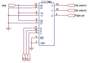
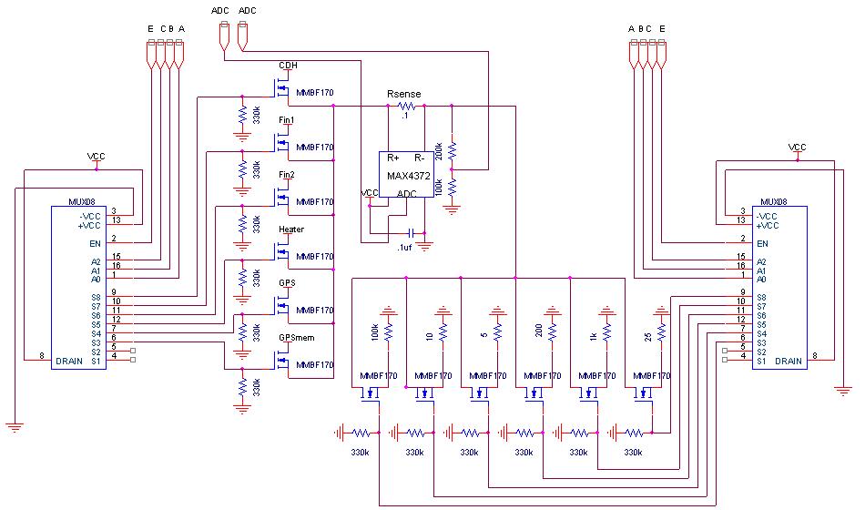
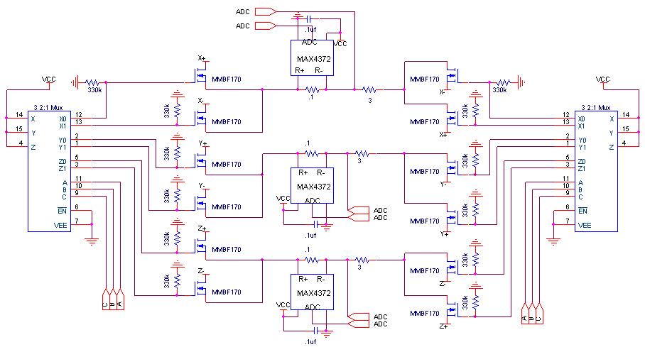
Circuitry Schematics
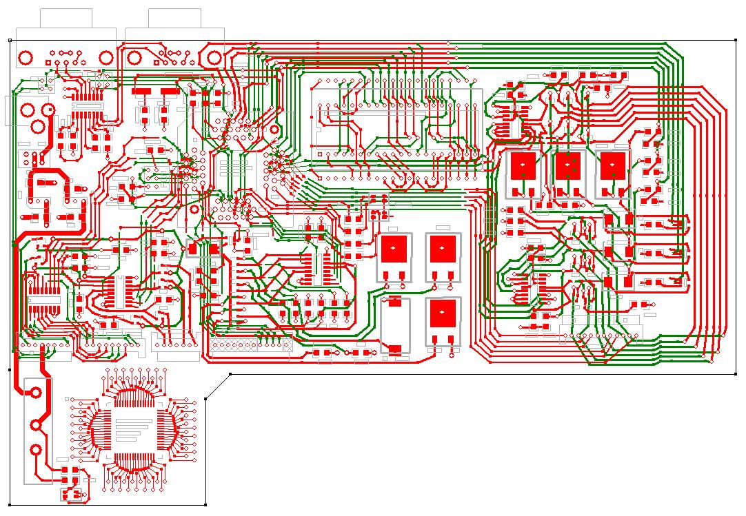
PCB Cad Layout
-
ExpressPCB
CAD File (PCB)
- 5V / 12V Shows Regulator
Connections
- MCU Supporting components
- LCD & Driver Circuit
- Includes STK501 TQFP64 ZIF
Socket Footprint
- Includes Mega128 Solder Pad w/
Through Holes
-
Rasterized Drawing
(JPG)
-
Vector 1:1 Printout (PDF)
- PCB Errors
- PGM header should be connected
to TX0 and RX0 rather than MISO/MOSI.
- Short R3, R20, R37, R39, R41
- Don't Populate R4, R19, R38,
R40, R42
- Pulldowns should be 330k
- LEDs should be 330 ohms
- Short Capacitors On Current
Sensors For X Y Z coils.
(Cap should be Vcc --> GND, not Vcc --> Port Pin)
- Remove solder mask layer above
LEDs & Power Resistors
- Serial Port Startup issue
remains unsolved
|
|