Stepper Motor Indexer & Decoder
|
||
|
Introduction |
High Level | Hardware
Design | Software Design |
||
|
|
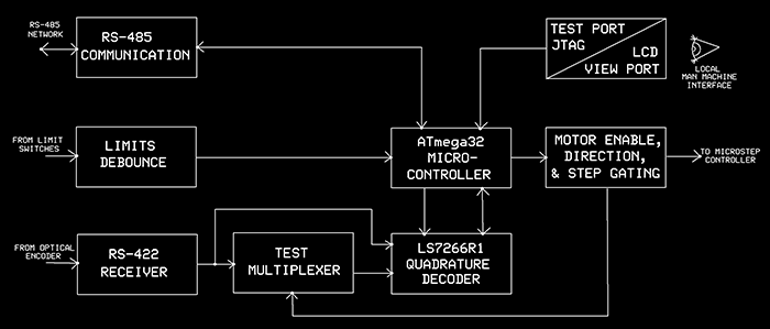
4.3 HardwareShown below is a bock diagram of the hardware we built with its three
major interfaces:
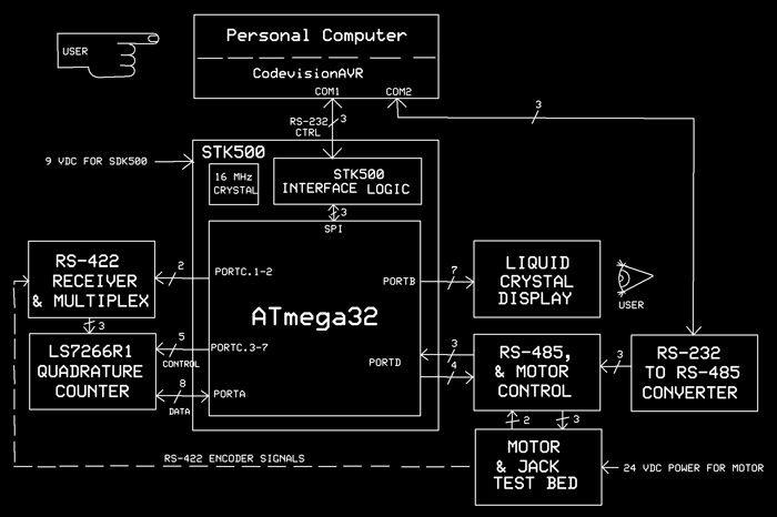
4.3 Structure of the Hardware PrototypeShown below is the structure of the hardware prototype. Initially we
built a stand alone prototype but while the card basically worked but
occasionally printed random characters to the LCD display. Even with most
chips removed this behavior was still present. We then built the
configuration below which consists of two wing boards in the female
expander headers of the STK500. This was most useful as we had the RS-232
as a backup for communications as well as the LEDs for troubleshooting.
The pin assignments on the motor controller were made to minimize signals
going between ports A and C on the left and ports B and D on the right.
There were 5 signals which needed to be jumpered between boards.
|
|