Stepper Motor Indexer & Decoder
|
||
|
Introduction |
High Level | Hardware
Design | Software Design |
||
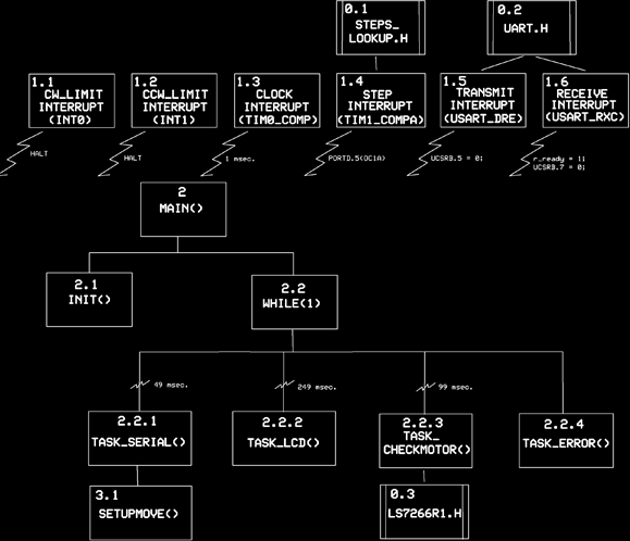
4.1 SoftwareShown below is a structure diagram of our software. There are six interrupts. The first two halt the motor when a hardware limit switch is engaged. The clock interrupt forms the basis for time measurement and is used in task scheduling. The resolution of our clock is 1 millisecond +/- .005 per cent.
Note that times for invoking the three tasks: task_serial() = 49
milliseconds, task_lcd() = 249 milliseconds, and task_checkmotor() = 99
milliseconds. These tasks are called by While(1) which constantly monitors
Clock Interrupt updates. The Step Interrupt is a state machine interrupt
which keeps track of motor position and which updates itself by means of a
look up table. The transmit and receive interrupts form the basis of
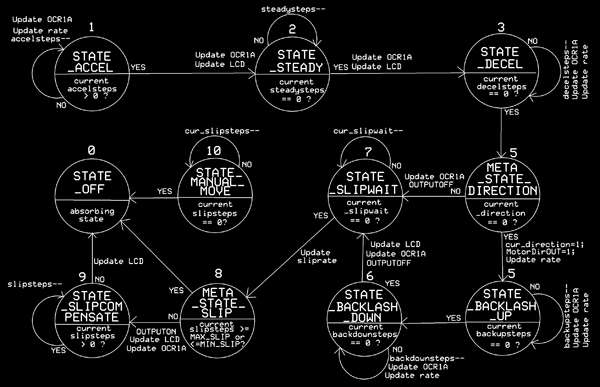
communication with the host computer via RS-485 and are in the file uart.h. 4.2 State MachineThere are eleven states in the state machine two of which are meta or transient states: states 5 and 8. The motor controller spends most of its time in the OFF state, state 0. When commanded to move state 1 is entered, then state 2 and finally state 3. At his point a decision is made by meta-state 5 as to whether backlash (states 5 and 6) is applied or not. In either case, state 7 is entered for a final reading of the decoder. Once the decoder is read meta-state 8 is entered and a decision is made as whether to apply slip compensation or not. In either case, the state machine ends in state 0, the OFF state. State 10 is for tweaking or jogging the motor in small steps.
|
||