Eye Snake - Low-Level Design
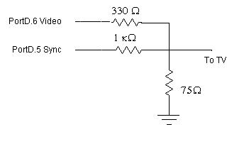
Hardware Design
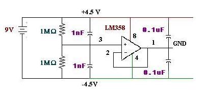
Our EOG circuit can be successfully run on two 9V batteries for each of the horizontal sensing and vertical sensing circuit boards. The power circuit, taken from a previous BioNB440 RF-linked EMG final project, is designed to split the rails in +4.5 and –4.5 rails. Note: The reference electrode placed behind your ear or forehead is hooked to ground.
Software Design
(view the source code here)The program started off with the video framework from the course,
except with no sound.
The first thing added was a basic one-pixel-per-length snake to move
around the screen. This part was fairly simple and had no complications.
After that, screen boundary conditions and collision detection with a randomly
generated fruit were added, both of which again were fairly simple as
the random generation is simply done by two calls to the Math.rand() function and
the collision detection consists of just checking the position of the snake's head
with the other positions (fruit, rest of snake).
The next step consisted of updating the graphics. Now, indead of single-pixel snake
and "fruits", we created 6x6 bitmap images of five different types of fruits and the
snake's head and tail.
Initially, they were 8x8 bitmaps with the snake's width being 6 pixels, but it seemed
that the logic to determine the snake's "cornering" (image transition from horizontal
to vertical or vice versa, since snake does not fill entire bitmap) seemed to be taking
too long and causing sync issues, so they were reduced to 6x6.
Additional logic had to be added to draw the snake's head and tail pointing in the correct
direction, as well as constraining the randomly generated fruit locations to align to the
screen grid of 6x6 cells.
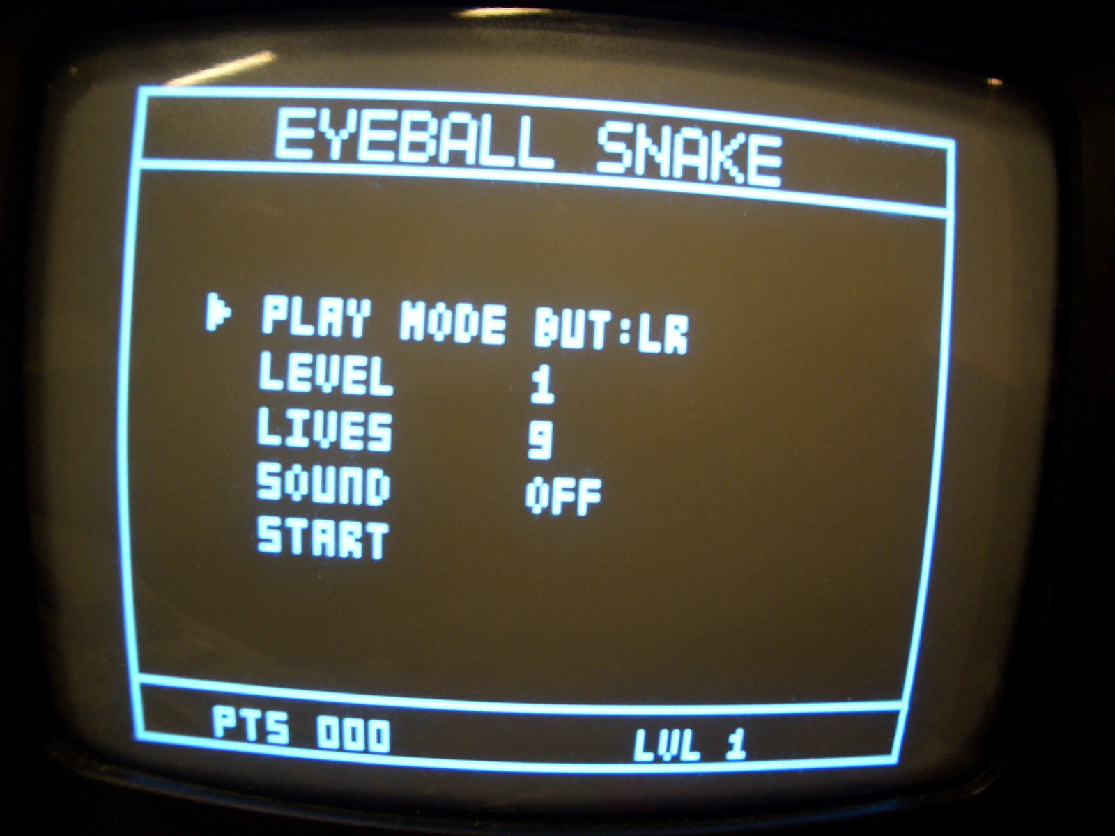
After that, we added up/down buttons to the initial left/right to control the snake. Now,
instead of left/right being 90deg turns, "up" corresponds to screen up, "down" to screen down,
"left" to screen left, and "right" to screen right. Thus, if the snake is traveling horizontally,
you can only turn up or down, and if it's traveling vertically on the screen, you can only turn
left or right.
Finally, we started adding external input from the electrodes to control the screen.
Initially, we started with the left/right only control scheme, since the left/right signal
was much cleaner and easier to calibrate. Even then, however, the signal had a tendency to
go flat and drop below threshholds for left/right, causing the "center" signal to evaluate to
left and the "right" signal to evaluate to an indeterminate value. However, if the signal
levels were distinct enough and the threshhold values in the code were properly set,
reading and decoding the signal from the ADC was straight-forward.
Calibrating the up/down signal was even more troublesome, but when it was set up correctly,
there were still initially problems with the directions being decoded. As it seemed that
the values were being read in correctly, we thought that it might be a problem with
debouncing. Since reading up/down and left/right requires two A/D conversions, we split it up
between frames - one frame left/right is read, then mux is set to the other pin and the
next frame up/down is read.
However, this causes a debounce for up/down or left/right to take 8 frames to go from not-pushed to
pushed back to not-pushed. So since left/right and up/down commands need to be alternated for
there to be any effect (eg. turning "up" while already going up or down has no effect), we decided
that removing debouncing would have no effect and was worth a try; and indeed it did work.
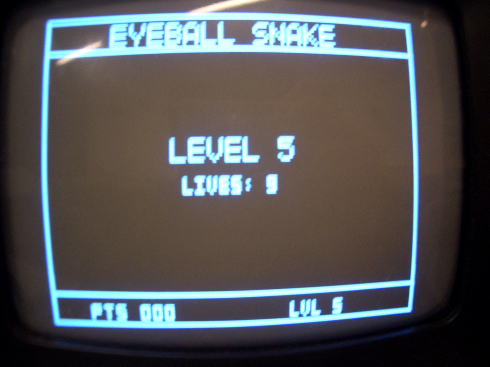
After getting those working (mostly), we moved on to adding multiple levels and lives. For each
new level, the starting speed increases, the starting length of the snake is incremented, and a
new obstacle is added. The obstacles are randomly generated in the same way as the fruit, and when
you die, your lives are decremented, and the speed and length are reset to the level's starting
values (length and speed are incremented each time you eat a fruit).
All in all, the biggest software problem we encountered was trying to draw/erase too many pixels at a time to the screen in one frame. To resolve the issue, we added several state machines to divide the drawing/erasing over several frames. And anything that had to be erased and redrawn in the same frame was always put together to occur in the same frame so no flickering occured.